
Direct Ink Writing of Phenylethynyl End-Capped Oligoimide/SiO2 to Additively Manufacture High-Performance Thermosetting Polyimide Composites

 ,
,
Abstract
:1. Introduction
2. Materials and Methods
2.1. Materials
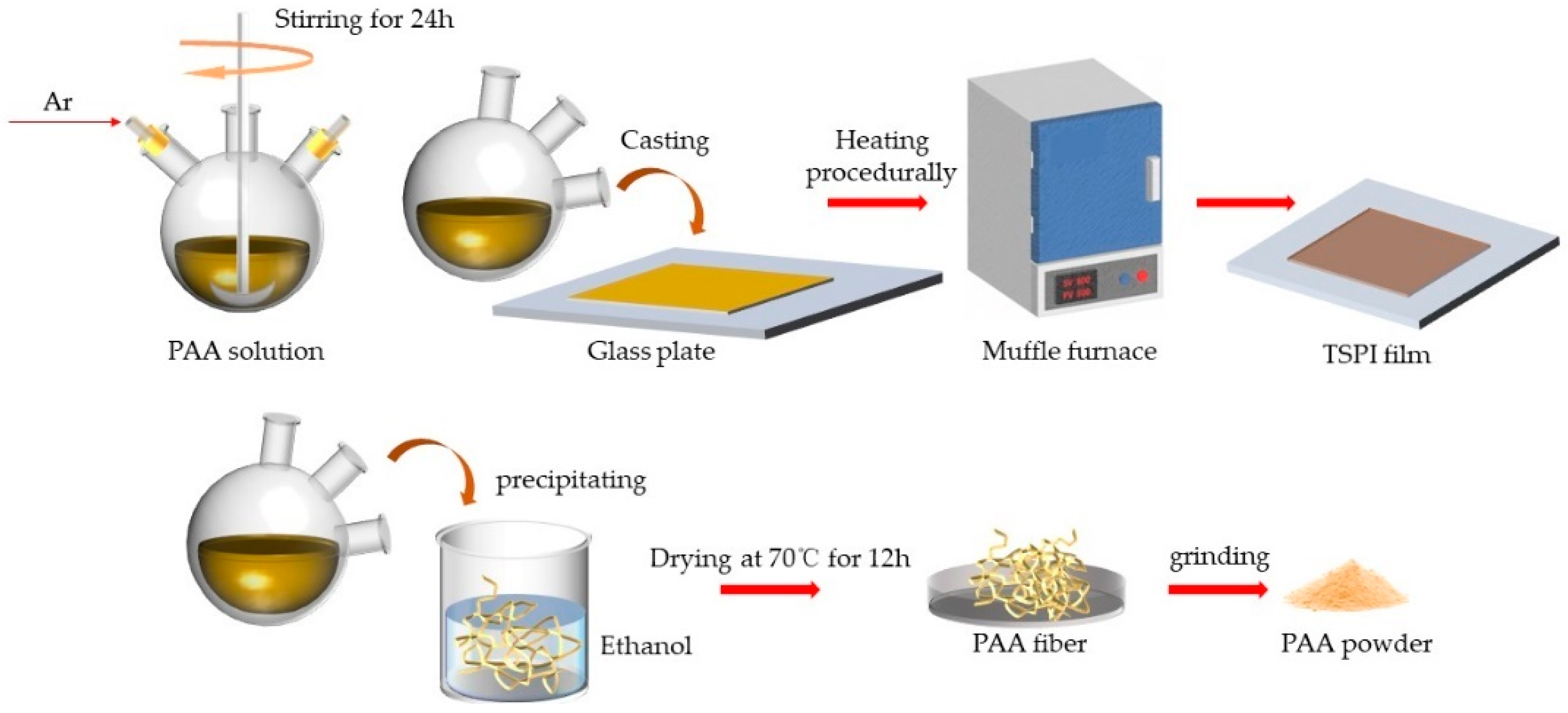
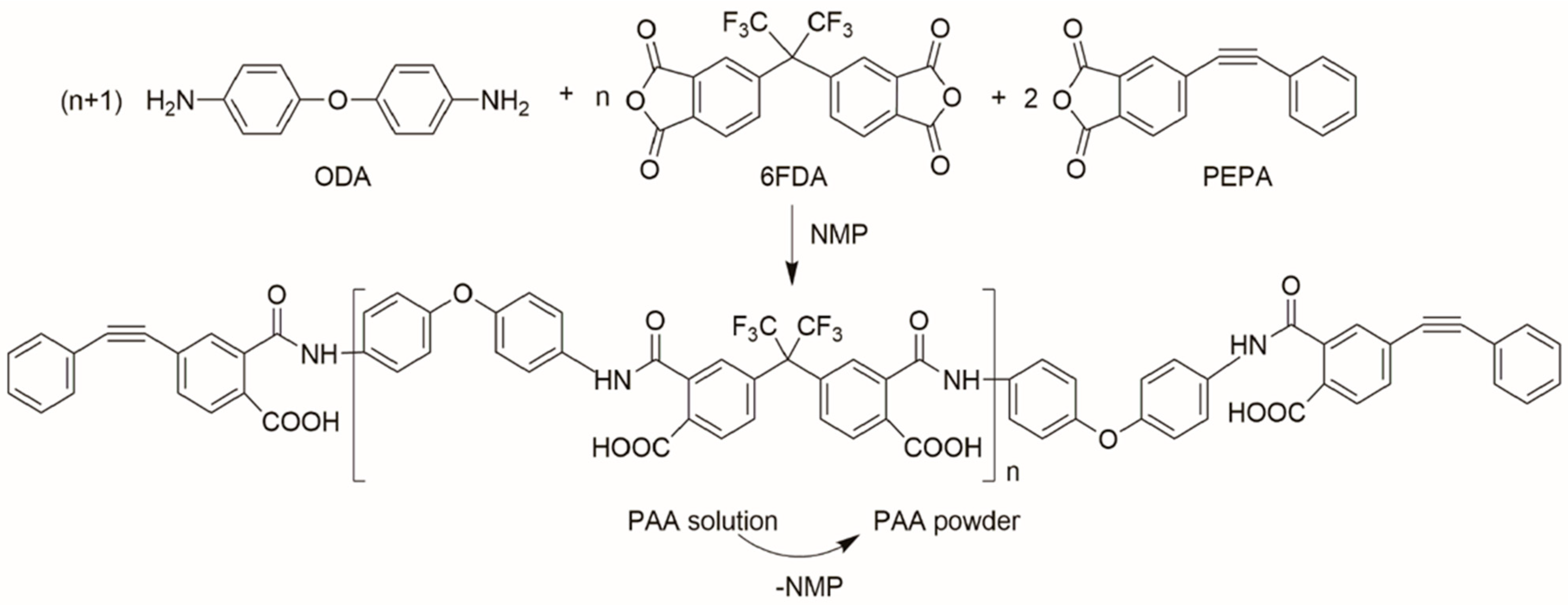
2.2. Preparation of Thermosetting Polyimide and Polyamide Acid (PAA) Powders
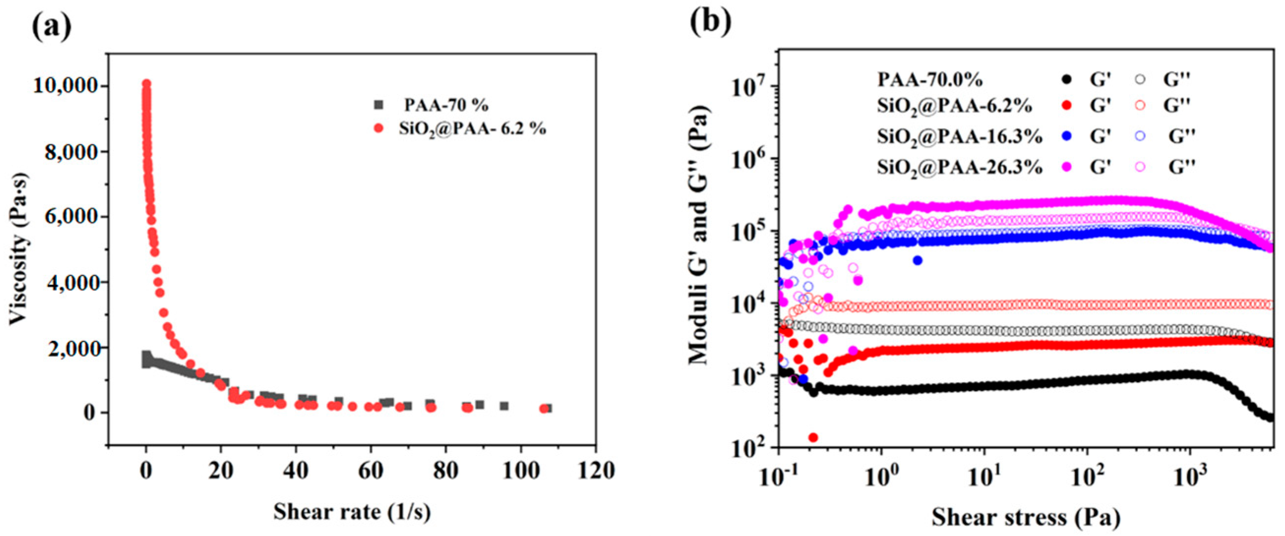
2.3. Preparation of Inks and 3D Printing of Thermoset Objects
2.4. Characterizations
3. Results and Discussion
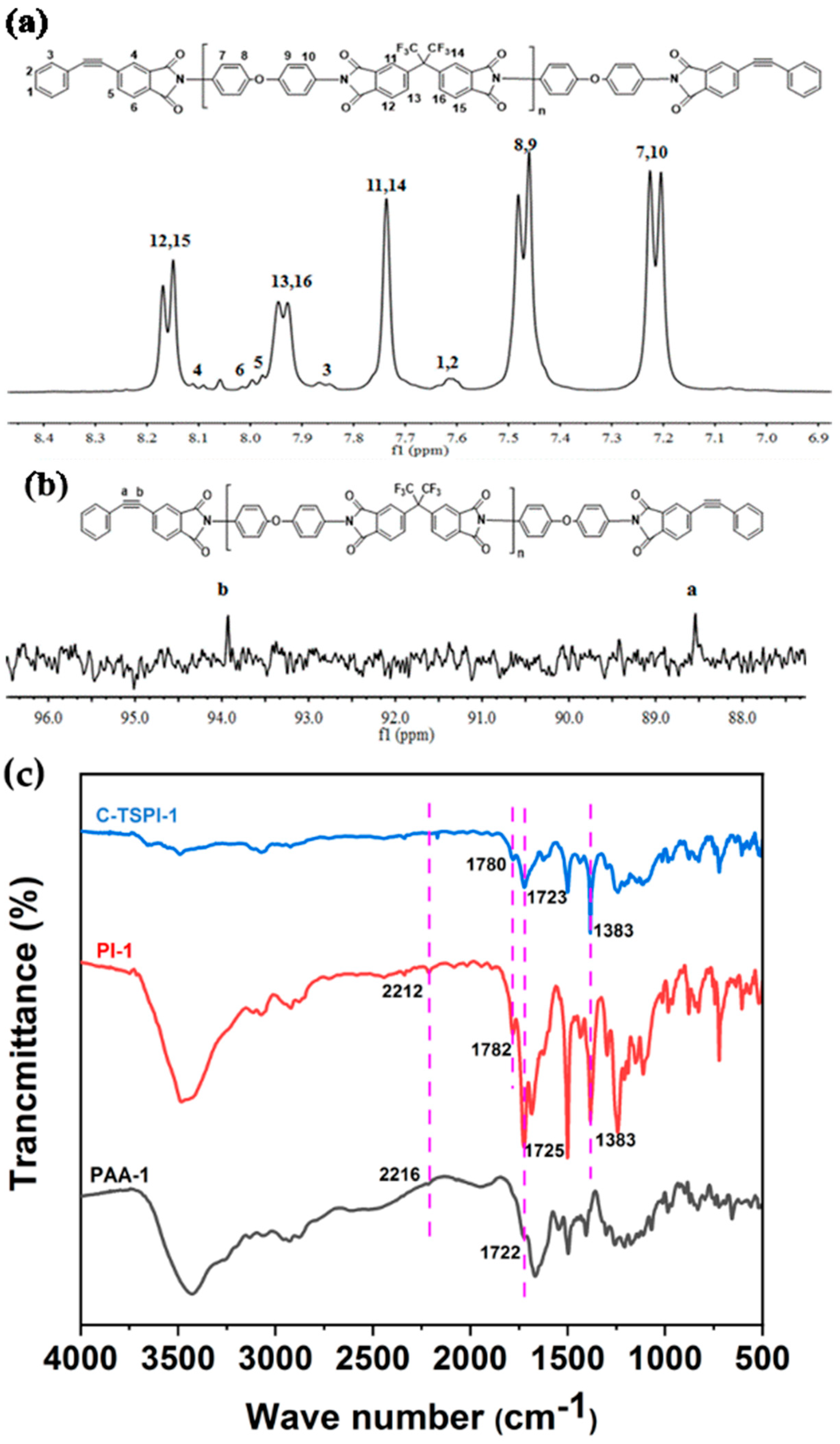
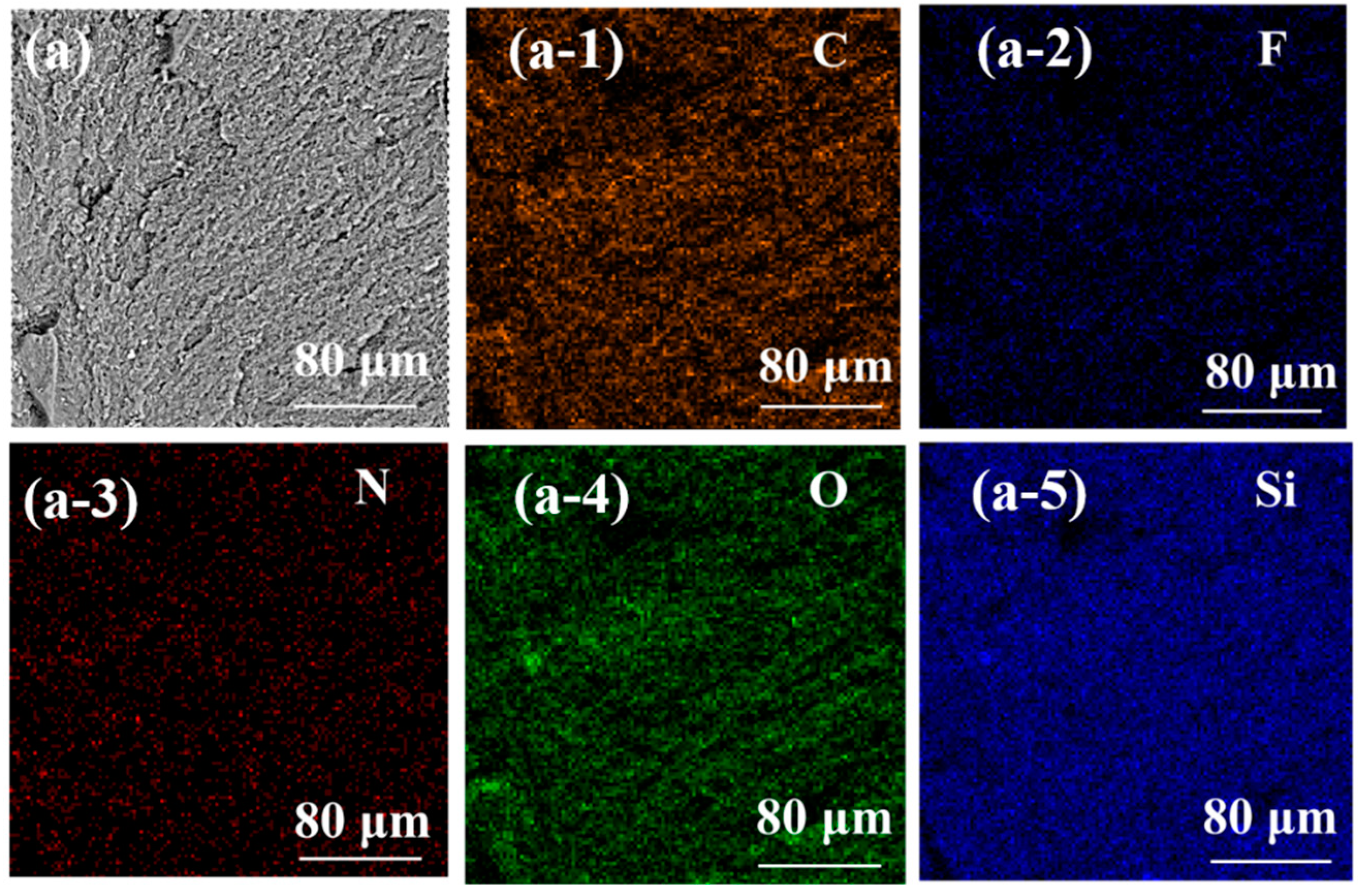
3.1. Chemical Structures of Uncured Polyimide and Cured Thermosetting Polyimide
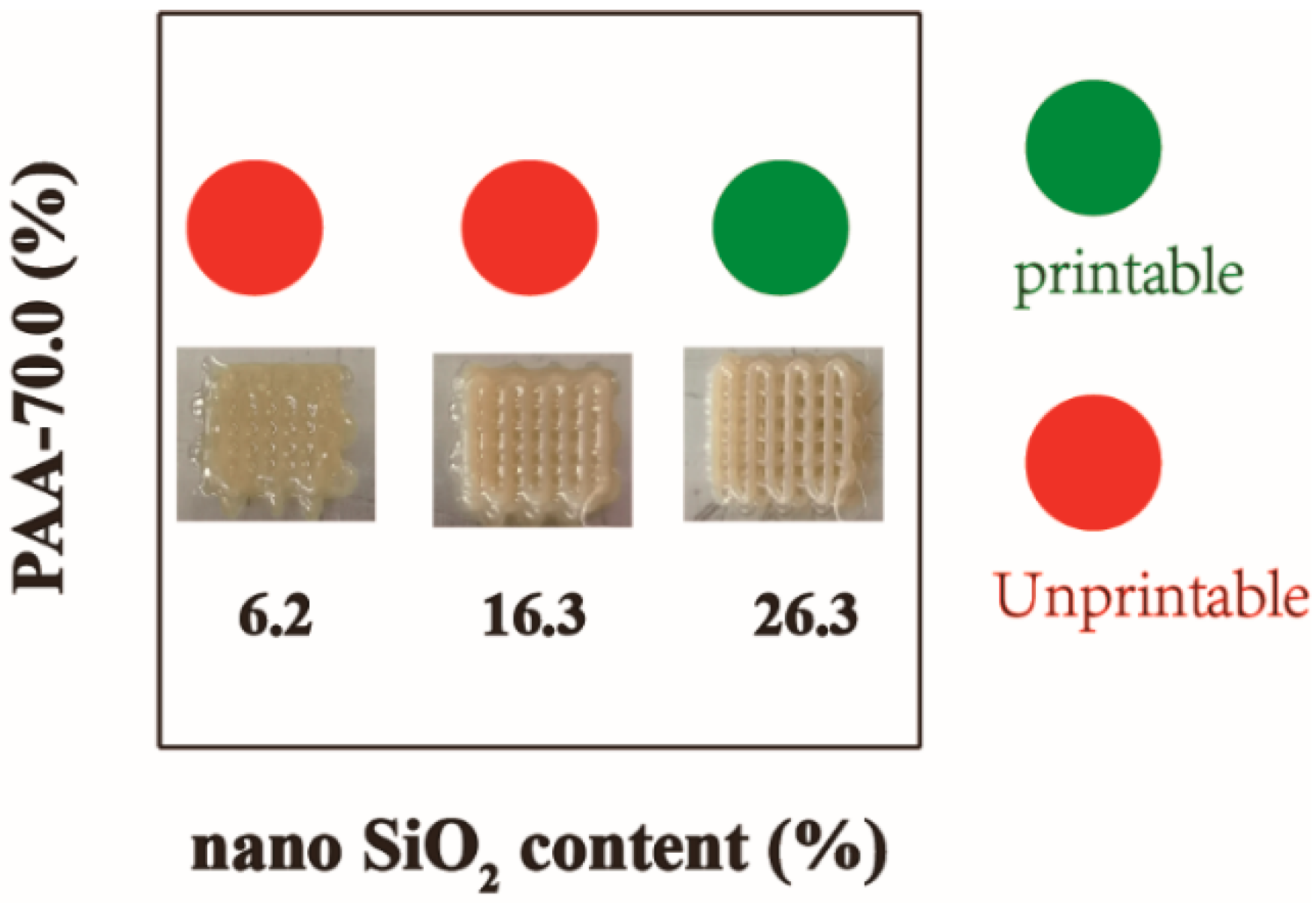
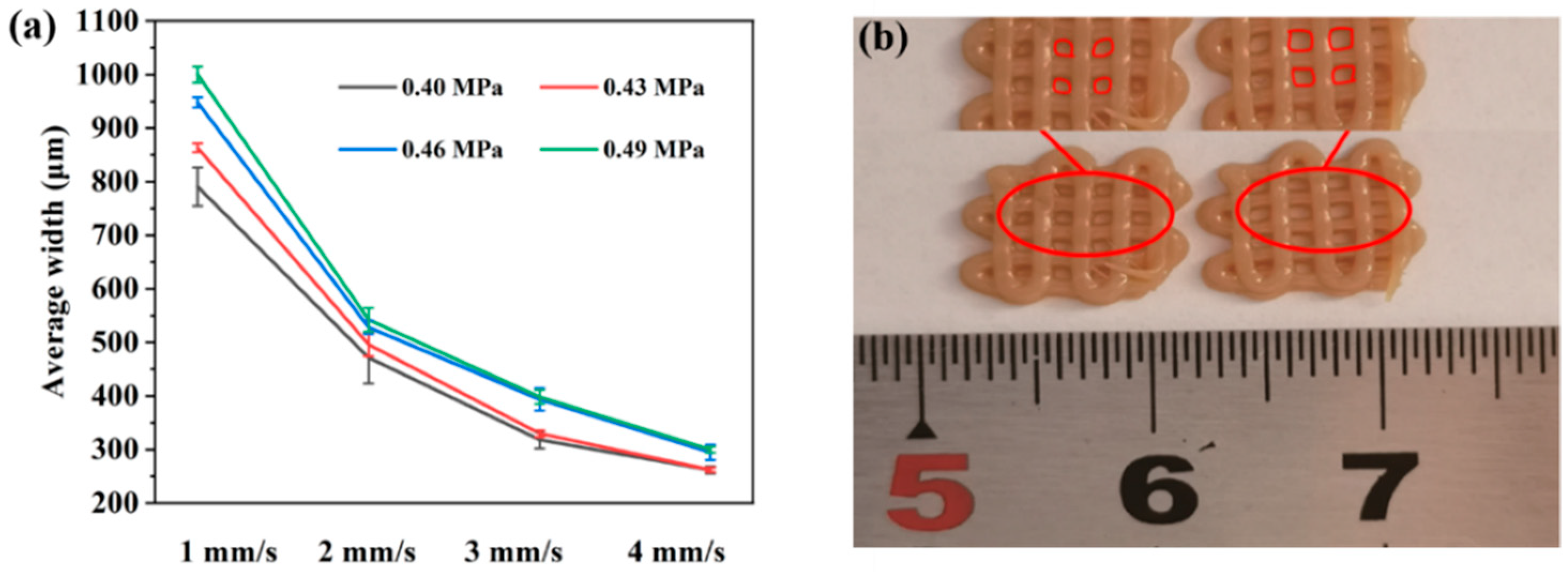
3.2. Three-Dimensional Printing of SiO2@TSPI Composites Using Direct Ink Writing (DIW)
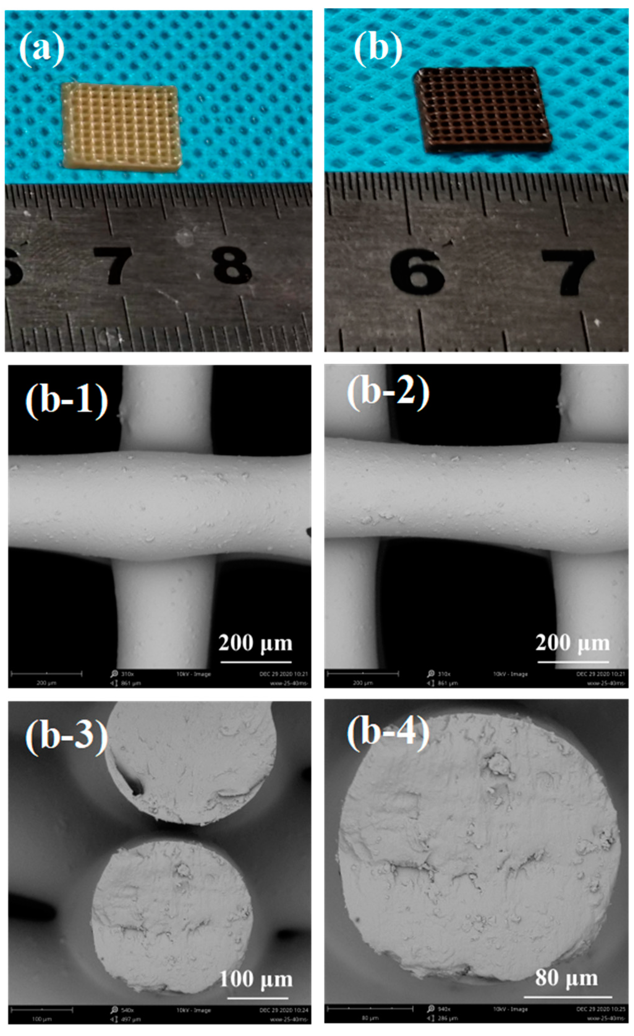
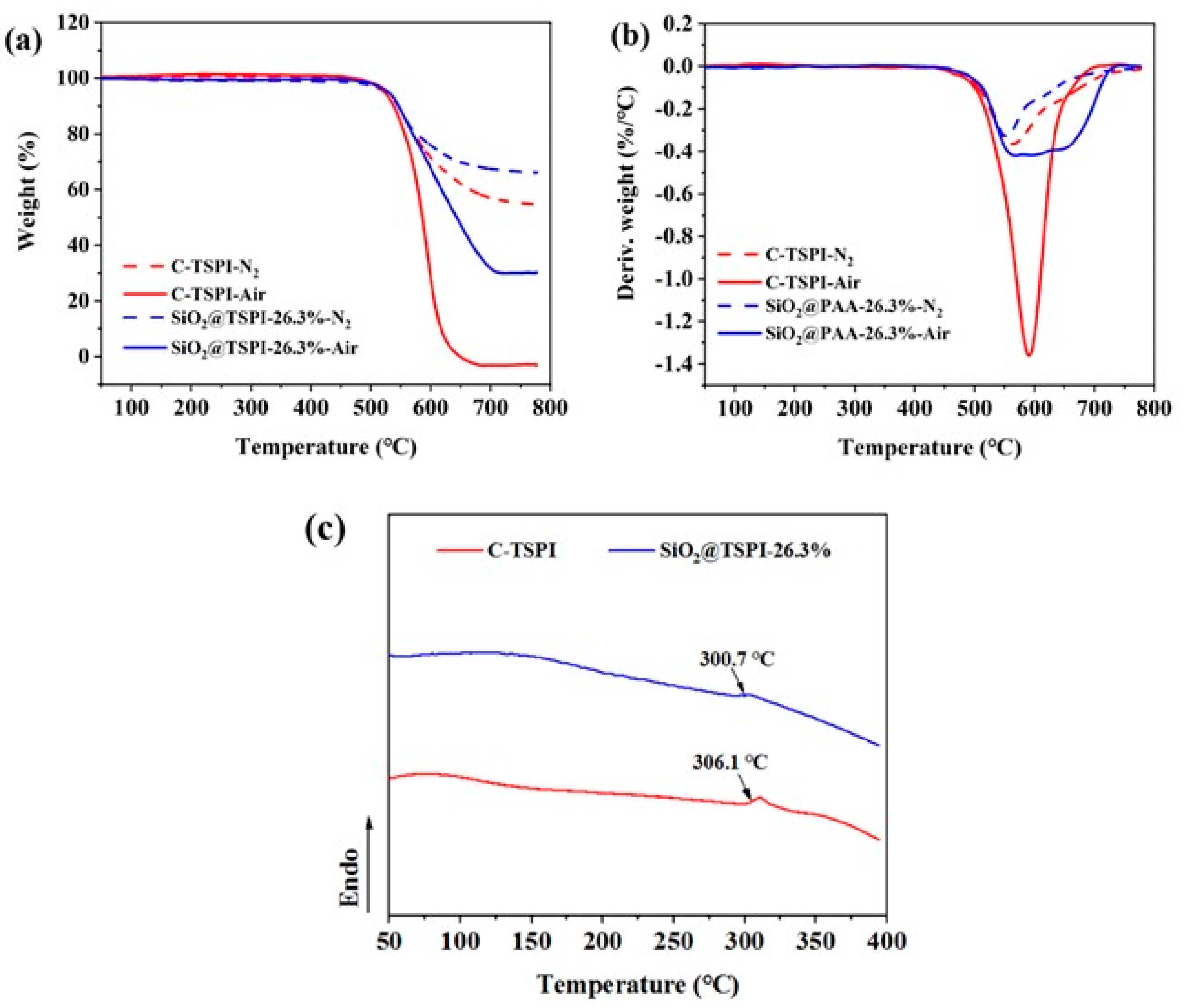
3.3. Thermal Stability of TSPI Films and Printed SiO2@TSPI-26.3%
3.4. Mechanical Properties of Printed Specimens
4. Conclusions
Author Contributions
Funding
Institutional Review Board Statement
Informed Consent Statement
Data Availability Statement
Conflicts of Interest
References
- Hou, Q.; Grijpma, D.W.; Feijen, J. Porous polymeric structures for tissue engineering prepared by a coagulation, compression moulding and salt leaching technique. Biomaterials 2003, 24, 1937–1947. [Google Scholar] [CrossRef]
- Jiang, S.; Reich, S.; Uch, B.; Hu, P.; Agarwal, S.; Greiner, A. Exploration of the Electrical Conductivity of Double-Network Silver Nanowires/Polyimide Porous Low-Density Compressible Sponges. ACS Appl. Mater. Interfaces 2017, 9, 34286–34293. [Google Scholar] [CrossRef] [PubMed]
- Meador, M.A.; Wright, S.; Sandberg, A.; Nguyen, B.N.; Van Keuls, F.W.; Mueller, C.H.; Rodriguez-Solis, R.; Miranda, F.A. Low dielectric polyimide aerogels as substrates for lightweight patch antennas. ACS Appl. Mater. Interfaces 2012, 4, 6346–6353. [Google Scholar] [CrossRef]
- Nguyen, T.; Wang, X. Multifunctional composite membrane based on a highly porous polyimide matrix for direct methanol fuel cells. J. Power Sources 2010, 195, 1024–1030. [Google Scholar] [CrossRef]
- Patel, Y.S.; Patel, H.S. Thermoplastic-thermosetting merged polyimides via furan-maleimide Diels–Alder polymerization. Arab. J. Chem. 2017, 10, S1373–S1380. [Google Scholar] [CrossRef] [Green Version]
- Yoo, T.; Kim, K.; Han, P.; Jang, W.; Han, H. Norbornene end-capped polyimide for low CTE and low residual stress with changes in the diamine linkages. Macromol. Res. 2015, 23, 776–786. [Google Scholar] [CrossRef]
- Mushtaq, N.; Chen, G.; Sidra, L.R.; Liu, Y.; Fang, X. Synthesis and crosslinking study of isomeric poly(thioether ether imide)s containing pendant nitrile and terminal phthalonitrile groups. Polym. Chem. 2016, 7, 7427–7435. [Google Scholar] [CrossRef]
- Luo, Y.; Sun, J.; Wang, J.; Jin, K.; He, F.; Fang, Q. A Novel Thermo-Polymerizable Aromatic Diamine: Synthesis and Application in Enhancement of the Properties of Conventional Polyimides. Macromol. Chem. Phys. 2016, 217, 856–862. [Google Scholar] [CrossRef]
- Yu, P.; Wang, Y.; Yu, J.; Zhu, J.; Hu, Z. Influence of different ratios of a-ODPA/a-BPDA on the properties of phenylethynyl terminated polyimide. J. Polym. Res. 2018, 25, 110. [Google Scholar] [CrossRef]
- Bershtein, V.A.; Sukhanova, T.E.; Krizan, T.D.; Keating, M.Y.; Grigoriev, A.I.; Egorov, V.M.; Yakushev, P.N.; Peschanskaya, N.N.; Vylegzhanina, M.E.; Bursian, A.E. Relationship of Processing Conditions to Structure and Properties in PMDA-ODA Polyimide. J. Macromol. Sci. Part B Phys. 2006, 44, 613–639. [Google Scholar] [CrossRef]
- Gladman, A.S.; Matsumoto, E.A.; Nuzzo, R.G.; Mahadevan, L.; Lewis, J.A. Biomimetic 4D printing. Nat. Mater. 2016, 15, 413–418. [Google Scholar] [CrossRef] [PubMed]
- Jiang, P.; Yan, C.; Guo, Y.; Zhang, X.; Cai, M.; Jia, X.; Wang, X.; Zhou, F. Direct ink writing with high-strength and swelling-resistant biocompatible physically crosslinked hydrogels. Biomater. Sci. 2019, 7, 1805–1814. [Google Scholar] [CrossRef] [PubMed]
- Leigh, S.J.; Bradley, R.J.; Purssell, C.P.; Billson, D.R.; Hutchins, D.A. A simple, low-cost conductive composite material for 3D printing of electronic sensors. PLoS ONE 2012, 7, e49365. [Google Scholar]
- Muth, J.T.; Vogt, D.M.; Truby, R.L.; Menguc, Y.; Kolesky, D.B.; Wood, R.J.; Lewis, J.A. Embedded 3D printing of strain sensors within highly stretchable elastomers. Adv. Mater. 2014, 26, 6307–6312. [Google Scholar] [CrossRef]
- Zarek, M.; Layani, M.; Cooperstein, I.; Sachyani, E.; Cohn, D.; Magdassi, S. 3D Printing of Shape Memory Polymers for Flexible Electronic Devices. Adv. Mater. 2016, 28, 4449–4454. [Google Scholar] [CrossRef] [PubMed]
- Li, V.C.; Dunn, C.K.; Zhang, Z.; Deng, Y.; Qi, H.J. Direct Ink Write (DIW) 3D Printed Cellulose Nanocrystal Aerogel Structures. Sci. Rep. 2017, 7, 8018. [Google Scholar] [CrossRef]
- Carneiro, O.S.; Silva, A.F.; Gomes, R. Fused deposition modeling with polypropylene. Mater. Des. 2015, 83, 768–776. [Google Scholar] [CrossRef]
- Chen, Z.; Yang, M.; Ji, M.; Kuang, X.; Qi, H.J.; Wang, T. Recyclable thermosetting polymers for digital light processing 3D printing. Mater. Des. 2021, 197, 109189. [Google Scholar] [CrossRef]
- Yang, K.; Grant, J.C.; Lamey, P.; Joshi-Imre, A.; Lund, B.R.; Smaldone, R.A.; Voit, W. Diels-Alder Reversible Thermoset 3D Printing: Isotropic Thermoset Polymers via Fused Filament Fabrication. Adv. Funct. Mater. 2017, 27, 1700318. [Google Scholar] [CrossRef]
- Tan, H.W.; Saengchairat, N.; Goh, G.L.; An, J.; Chua, C.K.; Tran, T. Induction Sintering of Silver Nanoparticle Inks on Polyimide Substrates. Adv. Mater. Technol. 2019, 5, 1900897. [Google Scholar] [CrossRef]
- Stepashkin, A.A.; Chukov, D.I.; Senatov, F.S.; Salimon, A.I.; Korsunsky, A.M.; Kaloshkin, S.D. 3D-printed PEEK-carbon fiber (CF) composites: Structure and thermal properties. Compos. Sci. Technol. 2018, 164, 319–326. [Google Scholar] [CrossRef]
- Ozbolat, V.; Dey, M.; Ayan, B.; Povilianskas, A.; Demirel, M.C.; Ozbolat, I.T. 3D Printing of PDMS Improves Its Mechanical and Cell Adhesion Properties. ACS Biomater. Sci. Eng. 2018, 4, 682–693. [Google Scholar] [CrossRef] [PubMed]
- Shi, Q.; Yu, K.; Kuang, X.; Mu, X.; Dunn, C.K.; Dunn, M.L.; Wang, T.; Jerry Qi, H. Recyclable 3D printing of vitrimer epoxy. Mater. Horiz. 2017, 4, 598–607. [Google Scholar] [CrossRef]
- Chandrasekaran, S.; Duoss, E.B.; Worsley, M.A.; Lewicki, J.P. 3D printing of high performance cyanate ester thermoset polymers. J. Mater. Chem. A 2018, 6, 853–858. [Google Scholar] [CrossRef]
- Chen, H.; Wang, X.; Xue, F.; Huang, Y.; Zhou, K.; Zhang, D. 3D printing of SiC ceramic: Direct ink writing with a solution of preceramic polymers. J. Eur. Ceram. Soc. 2018, 38, 5294–5300. [Google Scholar] [CrossRef]
- Zhao, Z.; Zhou, G.; Yang, Z.; Cao, X.; Jia, D.; Zhou, Y. Direct ink writing of continuous SiO2 fiber reinforced wave-transparent ceramics. J. Adv. Ceram. 2020, 9, 403–412. [Google Scholar] [CrossRef]
- Hegde, M.; Meenakshisundaram, V.; Chartrain, N.; Sekhar, S.; Tafti, D.; Williams, C.B.; Long, T.E. 3D Printing All-Aromatic Polyimides using Mask-Projection Stereolithography: Processing the Nonprocessable. Adv. Mater. 2017, 29, 1701240. [Google Scholar] [CrossRef] [Green Version]
- Rau, D.A.; Herzberger, J.; Long, T.E.; Williams, C.B. Ultraviolet-Assisted Direct Ink Write to Additively Manufacture All-Aromatic Polyimides. ACS Appl. Mater. Interfaces 2018, 10, 34828–34833. [Google Scholar] [CrossRef]
- Guo, Y.; Ji, Z.; Zhang, Y.; Wang, X.; Zhou, F. Solvent-free and photocurable polyimide inks for 3D printing. J. Mater. Chem. A 2017, 5, 16307–16314. [Google Scholar] [CrossRef]
- Li, X.; Yang, Y.; Zhang, Y.; Wang, T.; Yang, Z.; Wang, Q.; Zhang, X. Dual-method molding of 4D shape memory polyimide ink. Mater. Des. 2020, 191, 108606. [Google Scholar] [CrossRef]
- Xu, W.; Ding, Y.; Huang, R.; Zhu, Z.; Fong, H.; Hou, H. High-performance polyimide nanofibers reinforced polyimide nanocomposite films fabricated by co-electrospinning followed by hot-pressing. Appl. Polym. Sci. 2018, 135, 46869. [Google Scholar] [CrossRef]
- Gong, C.; Luo, Q.; Li, Y.; Giotto, M.; Cipollini, N.E.; Yang, Z.; Weiss, R.A.; Scola, D.A. Free radical initiated low temperature crosslinking of phenylethynyl (PE) end-capped oligomides. J. Polym. Sci. Part. A Polym. Chem. 2010, 48, 3950–3963. [Google Scholar] [CrossRef]
- Abbott, A.; Gibson, T.; Tandon, G.P.; Hu, L.; Avakian, R.; Baur, J.; Koerner, H. Melt extrusion and additive manufacturing of a thermosetting polyimide. Addit. Manuf. 2021, 37, 101636. [Google Scholar] [CrossRef]
- Herzberger, J.; Meenakshisundaram, V.; Williams, C.B.; Long, T.E. 3D Printing All-Aromatic Polyimides Using Stereolithographic 3D Printing of Polyamic Acid Salts. ACS Macro Lett. 2018, 7, 493–497. [Google Scholar] [CrossRef]


| Composition (Mole Ratio) | Designation of Polyamic Acids | Designation of Oligoimides | Mn (g/mol) Calculated | Mn (g/mol) Measured | PDI |
|---|---|---|---|---|---|
| PEPA/ODA/6FDA 2/24.47/23.57 | PAA | PI | 15,000 | 18,700 | 1.38 |
| PEPA/ODA/6FDA 2/8.13/7.13 | PAA-1 | PI-1 | 5000 | 5100 | 1.97 |
| Samples | Tg (°C) | T5% (°C) | T10% (°C) | Char Yield (%) |
|---|---|---|---|---|
| C-TSPI-Air | - | 519.0 | 536.6 | 0.00 |
| C-TSPI-NSi2 | 306.1 | 525.5 | 544.5 | 54.7 |
| SiO2@TSPI-26.3%-Air | - | 525.9 | 545.6 | 24.2 |
| SiO2@TSPI-26.3%-NSi2 | 300.7 | 529.1 | 546.5 | 66.0 |
| Sample | Tensile Strength (MPa) | Elastic Modulus (GPa) |
|---|---|---|
| C-TSPI | 118.95–125.60 | 2.60–3.15 |
| C- SiO2@TSPI-26.3% | 90.10–99.67 | 5.66–7.55 |
| SiO2@TSPI-26.3%-X | 89.36–102.56 | 2.29–3.58 |
| SiO2@TSPI-26.3%-Y | 32.96–38.22 | 1.75–1.87 |
| Printing Method | Structure | T5% (°C) a | Tensile Stress (MPa) | Dimensional Shrinkage (%) | Ref. |
|---|---|---|---|---|---|
| MPSL | 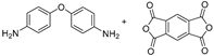 | 590 | 80 | 52 | [27] |
| SLA | 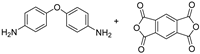 | 498 | --- | 48 | [34] |
| UV-DIW | 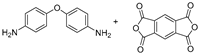 | 534 | --- | 45 | [28] |
| DLP |  | 420 | 24.9 | --- | [29] |
| FDM | 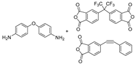 | ---- | 86 ± 11 | --- | [33] |
| DIW (this work) |  | 529 | 95 | 16 | --- |
Publisher’s Note: MDPI stays neutral with regard to jurisdictional claims in published maps and institutional affiliations. |
© 2022 by the authors. Licensee MDPI, Basel, Switzerland. This article is an open access article distributed under the terms and conditions of the Creative Commons Attribution (CC BY) license (https://creativecommons.org/licenses/by/4.0/).
Share and Cite
Li, K.; Ding, J.; Guo, Y.; Wu, H.; Wang, W.; Ji, J.; Pei, Q.; Gong, C.; Ji, Z.; Wang, X. Direct Ink Writing of Phenylethynyl End-Capped Oligoimide/SiO2 to Additively Manufacture High-Performance Thermosetting Polyimide Composites. Polymers 2022, 14, 2669. https://doi.org/10.3390/polym14132669
Li K, Ding J, Guo Y, Wu H, Wang W, Ji J, Pei Q, Gong C, Ji Z, Wang X. Direct Ink Writing of Phenylethynyl End-Capped Oligoimide/SiO2 to Additively Manufacture High-Performance Thermosetting Polyimide Composites. Polymers. 2022; 14(13):2669. https://doi.org/10.3390/polym14132669
Chicago/Turabian StyleLi, Keda, Jinghong Ding, Yuxiong Guo, Hongchao Wu, Wenwen Wang, Jiaqi Ji, Qi Pei, Chenliang Gong, Zhongying Ji, and Xiaolong Wang. 2022. "Direct Ink Writing of Phenylethynyl End-Capped Oligoimide/SiO2 to Additively Manufacture High-Performance Thermosetting Polyimide Composites" Polymers 14, no. 13: 2669. https://doi.org/10.3390/polym14132669