
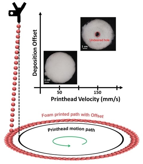
Deposition Offset of Printed Foam Strands in Direct Bubble Writing


Abstract
:
1. Introduction
2. Materials and Methods
2.1. Materials
2.2. Preparation of the Ink
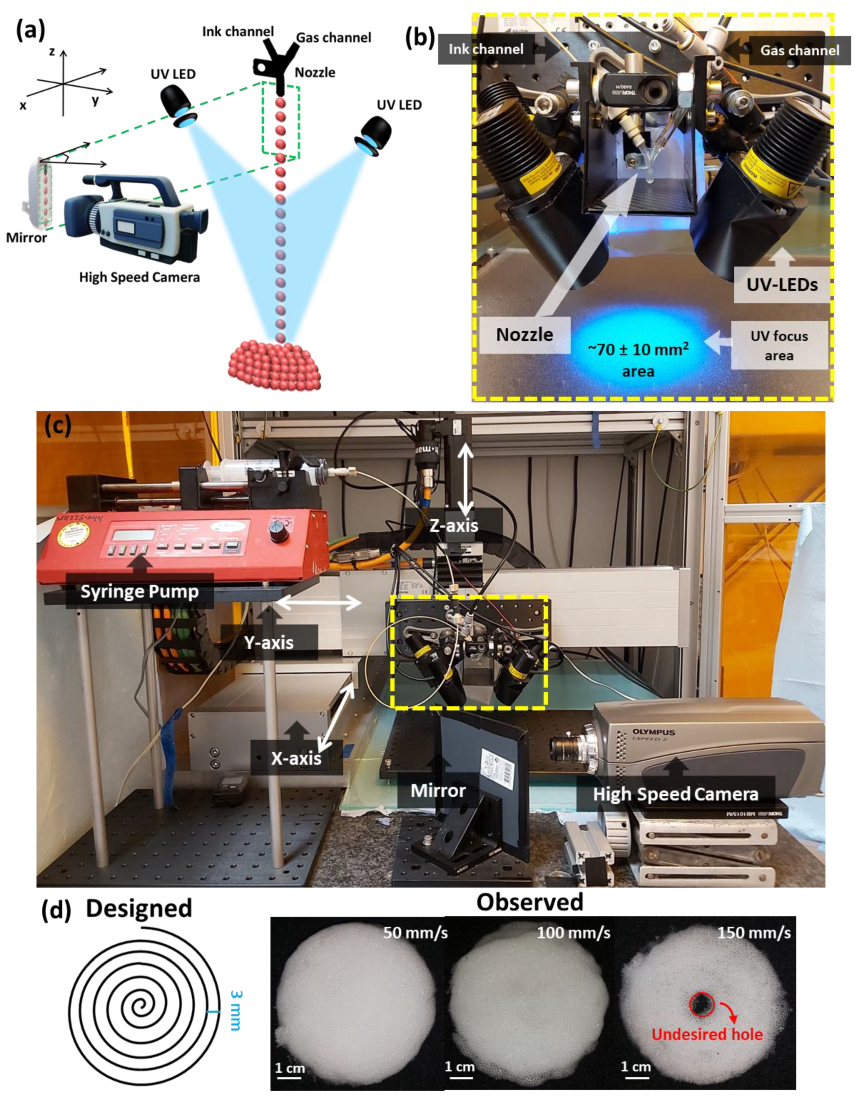
2.3. Printer Setup

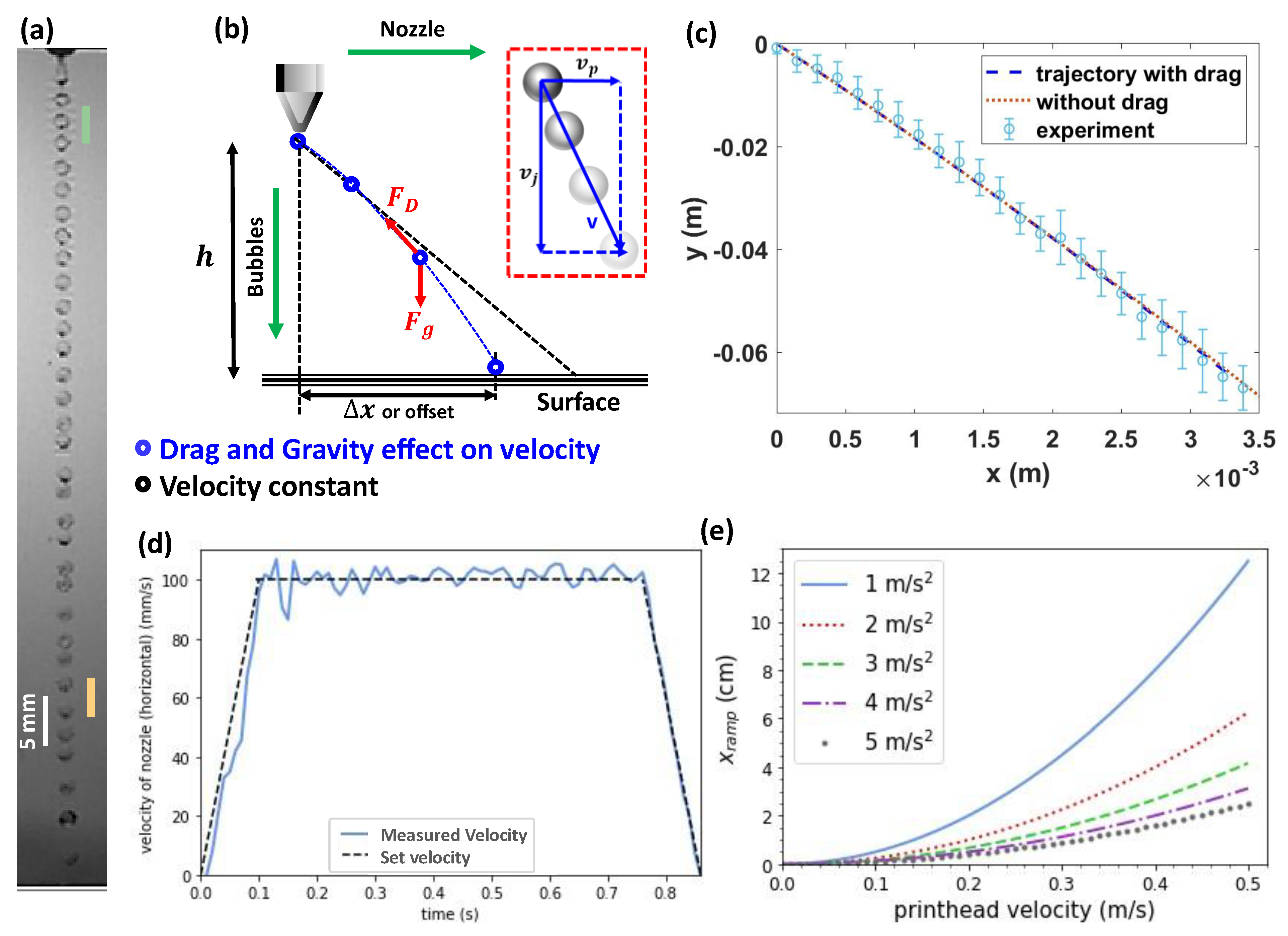
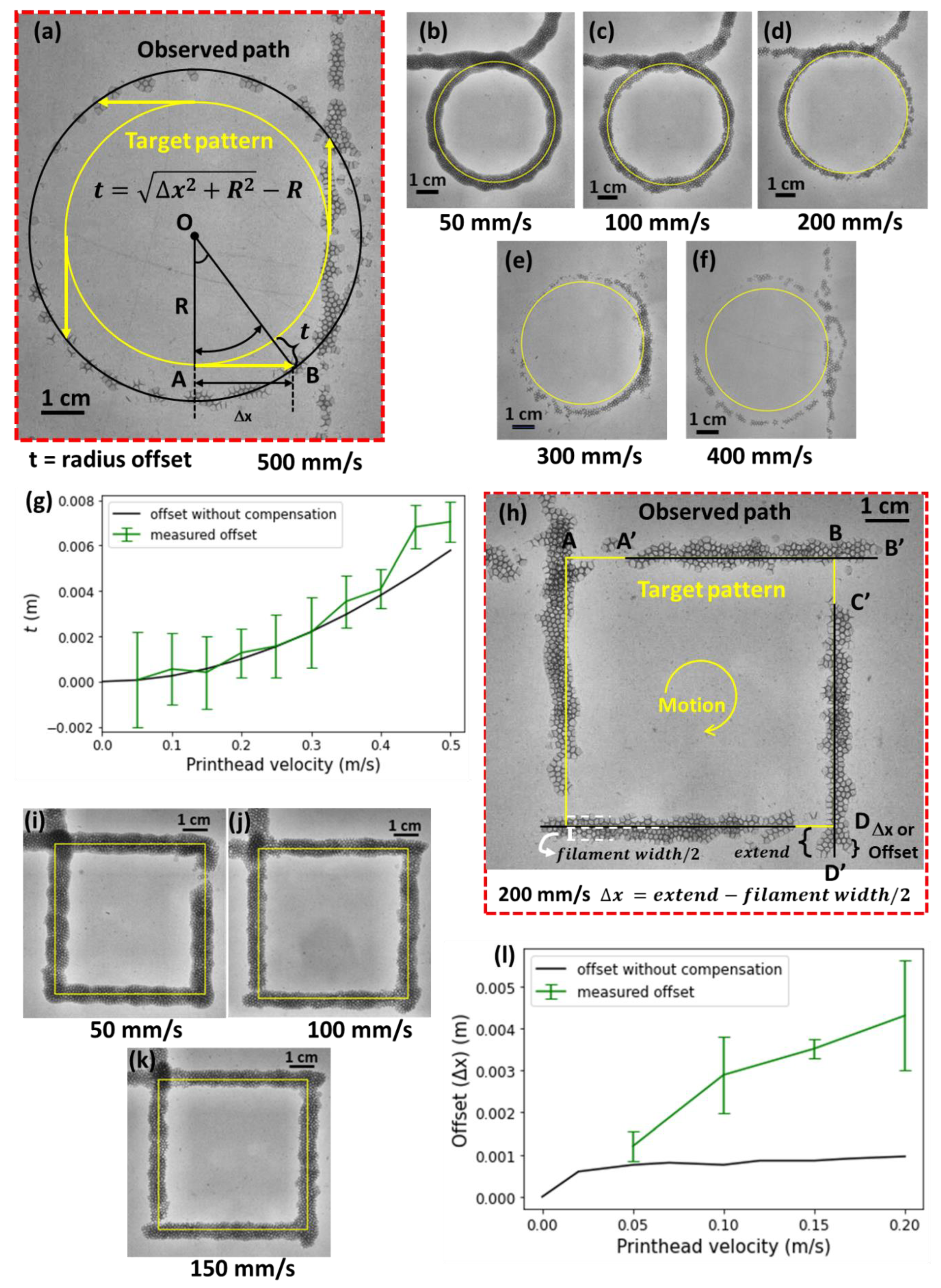
| Control Parameter | Figure 2 (Trajectory) | Figure 3 (Circle Pattern) | Figure 3 (Square Pattern) |
|---|---|---|---|
| Ink composition | Water + Tween20 (2%) | PEGDA700 + water (1:1) + Tween20 (2%) + TPO (1%) (w.r.t PEGDA) | PEGDA700 + water (1:1) + Tween20 (2%) + TPO (1%) (w.r.t PEGDA) |
| Ink Flow Rate (mL/min) | 12 | 15 | 15 |
| Gas in core | Compressed Air | Nitrogen | Nitrogen |
| Gas Pressure (kPa) | 3.5 | 7 | 7 |
| Printhead Velocity (m/s) | 0.1 | 0.05, 0.1, 0.2, 0.3, 0.4, 0.5 | 0.05, 0.1, 0.15, 0.2 |
| Printhead Acceleration (m/s2) | 1 | 1 | 1 |
| Nozzle-to-build platform distance (m) | 0.1 | 0.1 | 0.1 |
| Printhead trajectory dimensions (m) | 0.1 m | Diameter = 0.06 m | Side length = 0.06 m |
2.4. Image Processing
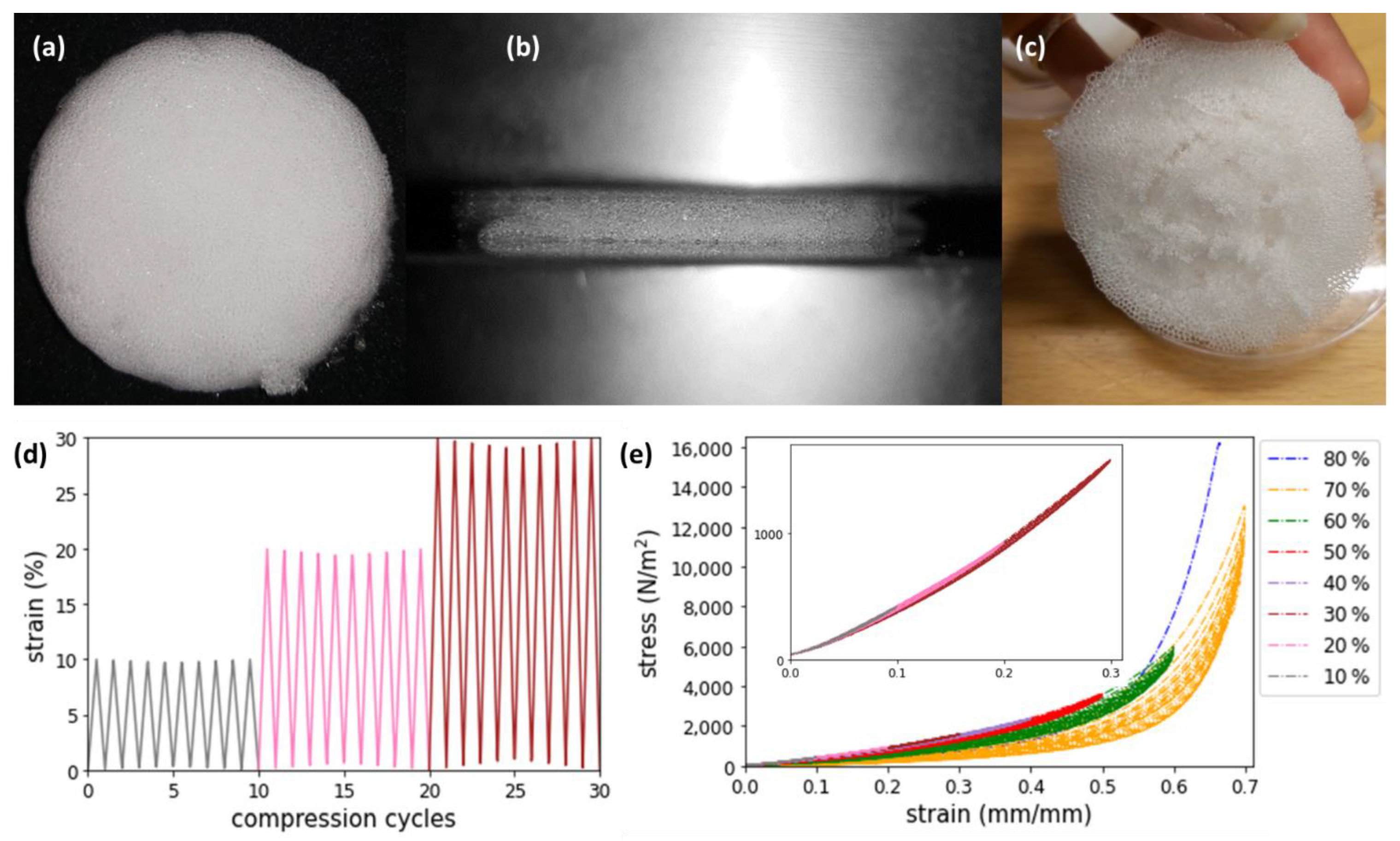
2.5. Cyclic Compression Testing
3. Results
4. Conclusions
Supplementary Materials
Author Contributions
Funding
Institutional Review Board Statement
Informed Consent Statement
Data Availability Statement
Acknowledgments
Conflicts of Interest
References
- Visser, C.W.; Amato, D.N.; Mueller, J.; Lewis, J.A. Architected Polymer Foams via Direct Bubble Writing. Adv. Mater. 2019, 31, 1904668. [Google Scholar] [CrossRef] [PubMed]
- Amato, D.N.; Amato, D.V.; Sandoz, M.; Weigand, J.; Patton, D.L.; Visser, C.W. Programmable Porous Polymers via Direct Bubble Writing with Surfactant-Free Inks. ACS Appl. Mater. Interfaces 2020, 12, 42048–42055. [Google Scholar] [CrossRef] [PubMed]
- Jiang, J.; Shea, G.; Rastogi, P.; Kamperman, T.; Venner, C.H.; Visser, C.W. Continuous High-Throughput Fabrication of Architected Micromaterials via In-Air Photopolymerization. Adv. Mater. 2021, 33, 2006336. [Google Scholar] [CrossRef] [PubMed]
- Damanpack, A.R.; Sousa, A.; Bodaghi, M. Porous PLAs with Controllable Density by FDM 3D Printing and Chemical Foaming Agent. Micromachines 2021, 12, 866. [Google Scholar] [CrossRef]
- Xu, C.; Christensen, K.; Zhang, Z.; Huang, Y.; Fu, J.; Markwald, R.R. Predictive Compensation-Enabled Horizontal Inkjet Printing of Alginate Tubular Constructs. Manuf. Lett. 2013, 1, 28–32. [Google Scholar] [CrossRef]
- Jang, D.; Kim, D.; Moon, J. Influence of Fluid Physical Properties on Ink-Jet Printability. Langmuir 2009, 25, 2629–2635. [Google Scholar] [CrossRef]
- Mostafaei, A.; Elliott, A.M.; Barnes, J.E.; Li, F.; Tan, W.; Cramer, C.L.; Nandwana, P.; Chmielus, M. Binder Jet 3D Printing—Process Parameters, Materials, Properties, Modeling, and Challenges. Prog. Mater. Sci. 2021, 119, 100707. [Google Scholar] [CrossRef]
- Zhang, L. Characteristics of Drop-on-Demand Droplet Jetting with Effect of Altered Geometry of Printhead Nozzle. Sens. Actuators Phys. 2019, 298, 111591. [Google Scholar] [CrossRef]
- Gibson, I.; Rosen, D.; Stucker, B. Material Jetting. In Additive Manufacturing Technologies; Springer: New York, NY, USA, 2015; pp. 175–203. ISBN 978-1-4939-2112-6. [Google Scholar]
- Chen, S.-C.; Yeh, Y.-C.; Chen, W.-L. Control of Ink-Jet Firing for Bubble-Jet Printer. Int. J. Electron. 2002, 89, 19–34. [Google Scholar] [CrossRef]
- Song, J.H.; Nur, H.M. Defects and Prevention in Ceramic Components Fabricated by Inkjet Printing. J. Mater. Process. Technol. 2004, 155–156, 1286–1292. [Google Scholar] [CrossRef]
- Miyanaji, H.; Momenzadeh, N.; Yang, L. Effect of Printing Speed on Quality of Printed Parts in Binder Jetting Process. Addit. Manuf. 2018, 20, 1–10. [Google Scholar] [CrossRef]
- Lee, H.-H.; Chou, K.-S.; Huang, K.-C. Inkjet Printing of Nanosized Silver Colloids. Nanotechnology 2005, 16, 2436–2441. [Google Scholar] [CrossRef] [PubMed]
- Jin, Y.; He, Y.; Gao, Q.; Fu, J.; Fu, G. Droplet Deviation Modeling and Compensation Scheme of Inkjet Printing. Int. J. Adv. Manuf. Technol. 2014, 75, 1405–1415. [Google Scholar] [CrossRef]
- Parab, N.D.; Barnes, J.E.; Zhao, C.; Cunningham, R.W.; Fezzaa, K.; Rollett, A.D.; Sun, T. Real Time Observation of Binder Jetting Printing Process Using High-Speed X-Ray Imaging. Sci. Rep. 2019, 9, 2499. [Google Scholar] [CrossRef]
- Rodriguez-Rivero, C.; Castrejón-Pita, J.R.; Hutchings, I.M. Aerodynamic Effects in Industrial Inkjet Printing. J. Imaging Sci. Technol. 2015, 59, 29–38. [Google Scholar] [CrossRef]
- van der Meulen, M.-J.; Reinten, H.; Wijshoff, H.; Versluis, M.; Lohse, D.; Steen, P. Nonaxisymmetric Effects in Drop-On-Demand Piezoacoustic Inkjet Printing. Phys. Rev. Appl. 2020, 13, 054071. [Google Scholar] [CrossRef]
- ISO 3386-1:1986; Polymeric Materials, Cellular Flexible—Determination of Stress-Strain Characteristics in Compression—Part 1: Low-Density Materials. ISO: Geneva, Switzerland, 1986. Available online: https://www.iso.org/cms/render/live/en/sites/isoorg/contents/data/standard/00/86/8683.html (accessed on 29 January 2022).
- ISO 3386-1:1986; Flexible Cellular Polymeric Materials–Determination of Stress-Strain Characteristics in Compression Part 1: Low-Density Materials. ISO: Geneva, Switzerland, 1986. Available online: http://yiqi-oss.oss-cn-hangzhou.aliyuncs.com/aliyun/900102001/technical_file/file_333998.pdf (accessed on 29 January 2022).
- Friedrich, L.; Begley, M. Corner Accuracy in Direct Ink Writing with Support Material. Bioprinting 2020, 19, e00086. [Google Scholar] [CrossRef]
- Alzoubi, M.F.; Tanbour, E.Y.; Al-Waked, R. Compression and Hysteresis Curves of Nonlinear Polyurethane Foams Under Different Densities, Strain Rates and Different Environmental Conditions. In Proceedings of the ASME 2011 International Mechanical Engineering Congress and Exposition, Denver, CO, USA, 11–17 November 2011; pp. 101–109. [Google Scholar]
- Bouchahdane, K.; Ouelaa, N.; Belaadi, A. Static and Fatigue Compression Behaviour of Conventional and Auxetic Open-Cell Foam. Mech. Adv. Mater. Struct. 2021, 1–14. [Google Scholar] [CrossRef]
- Calabrese, L.; Bonaccorsi, L.; Bruzzaniti, P.; Gullì, G.; Freni, A.; Proverbio, E. Zeolite Filled Siloxane Composite Foams: Compression Property. J. Appl. Polym. Sci. 2018, 135, 46145. [Google Scholar] [CrossRef]
- Hoo Fatt, M.S.; Chen, L. A Viscoelastic Damage Model for Hysteresis in PVC H100 Foam under Cyclic Loading. J. Cell. Plast. 2015, 51, 269–287. [Google Scholar] [CrossRef]
- Idriss, M.; El Mahi, A.; Assarar, M.; El Guerjouma, R. Damping Analysis in Cyclic Fatigue Loading of Sandwich Beams with Debonding. Compos. Part B Eng. 2013, 44, 597–603. [Google Scholar] [CrossRef]
- Jarrah, H.R.; Zolfagharian, A.; Hedayati, R.; Serjouei, A.; Bodaghi, M. Nonlinear Finite Element Modelling of Thermo-Visco-Plastic Styrene and Polyurethane Shape Memory Polymer Foams. Actuators 2021, 10, 46. [Google Scholar] [CrossRef]

Publisher’s Note: MDPI stays neutral with regard to jurisdictional claims in published maps and institutional affiliations. |
© 2022 by the authors. Licensee MDPI, Basel, Switzerland. This article is an open access article distributed under the terms and conditions of the Creative Commons Attribution (CC BY) license (https://creativecommons.org/licenses/by/4.0/).
Share and Cite
Rastogi, P.; Venner, C.H.; Visser, C.W. Deposition Offset of Printed Foam Strands in Direct Bubble Writing. Polymers 2022, 14, 2895. https://doi.org/10.3390/polym14142895
Rastogi P, Venner CH, Visser CW. Deposition Offset of Printed Foam Strands in Direct Bubble Writing. Polymers. 2022; 14(14):2895. https://doi.org/10.3390/polym14142895
Chicago/Turabian StyleRastogi, Prasansha, Cornelis H. Venner, and Claas Willem Visser. 2022. "Deposition Offset of Printed Foam Strands in Direct Bubble Writing" Polymers 14, no. 14: 2895. https://doi.org/10.3390/polym14142895
APA StyleRastogi, P., Venner, C. H., & Visser, C. W. (2022). Deposition Offset of Printed Foam Strands in Direct Bubble Writing. Polymers, 14(14), 2895. https://doi.org/10.3390/polym14142895