
Preparation of Novel Graphene/Silicone Rubber Nanocomposite Dielectric Foams


Abstract
:1. Introduction
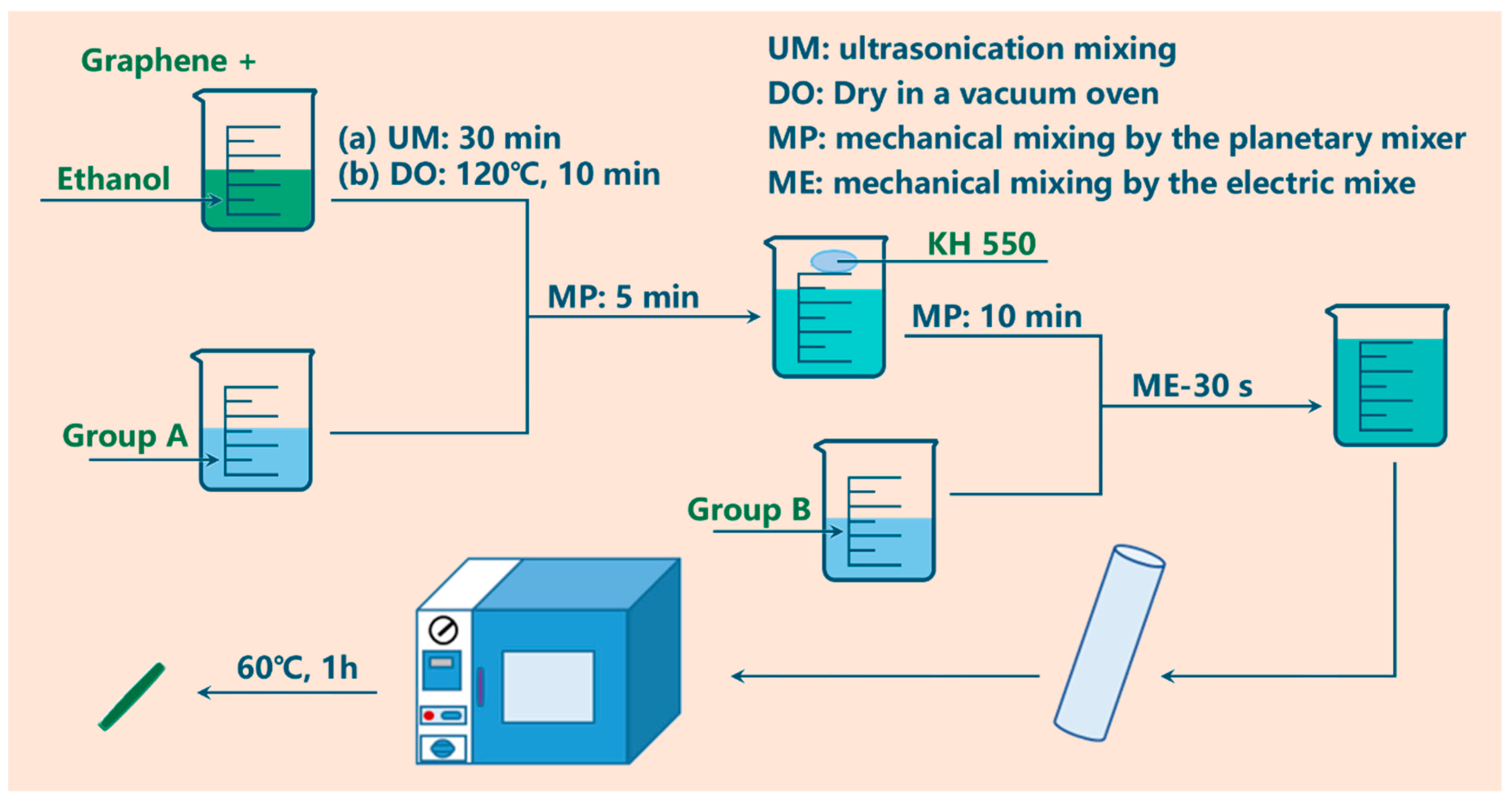
2. Experiments
Materials and Experiments
3. Morphology
4. Results and Discussion
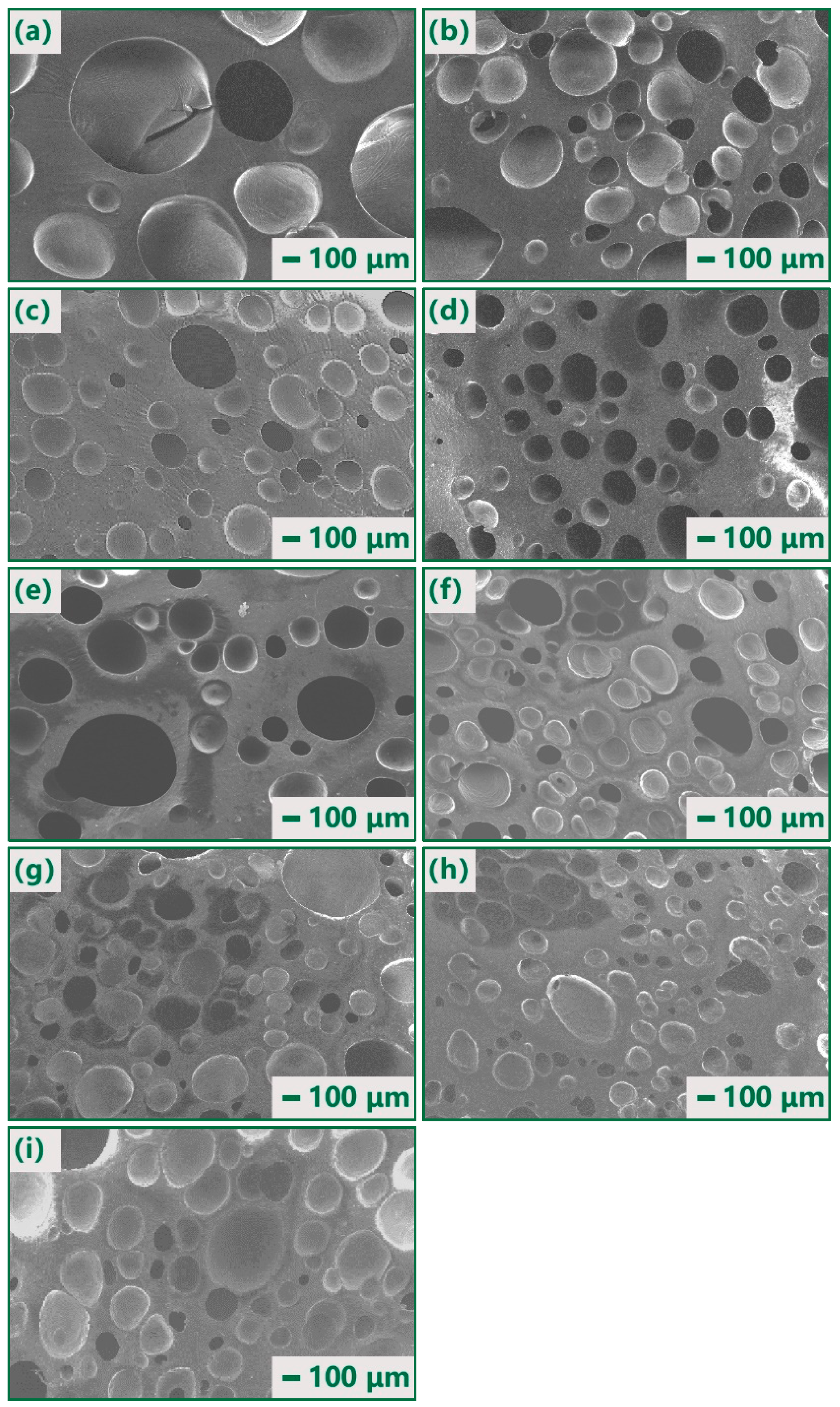
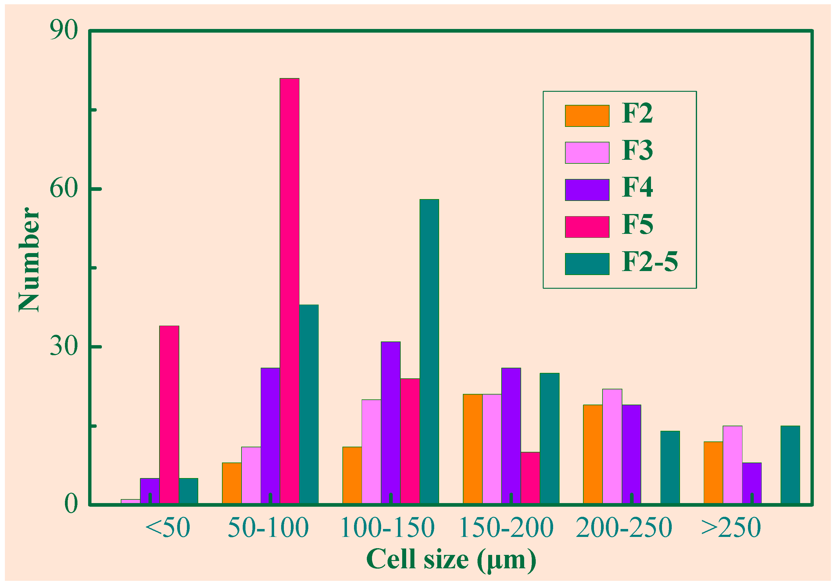
4.1. Morphology
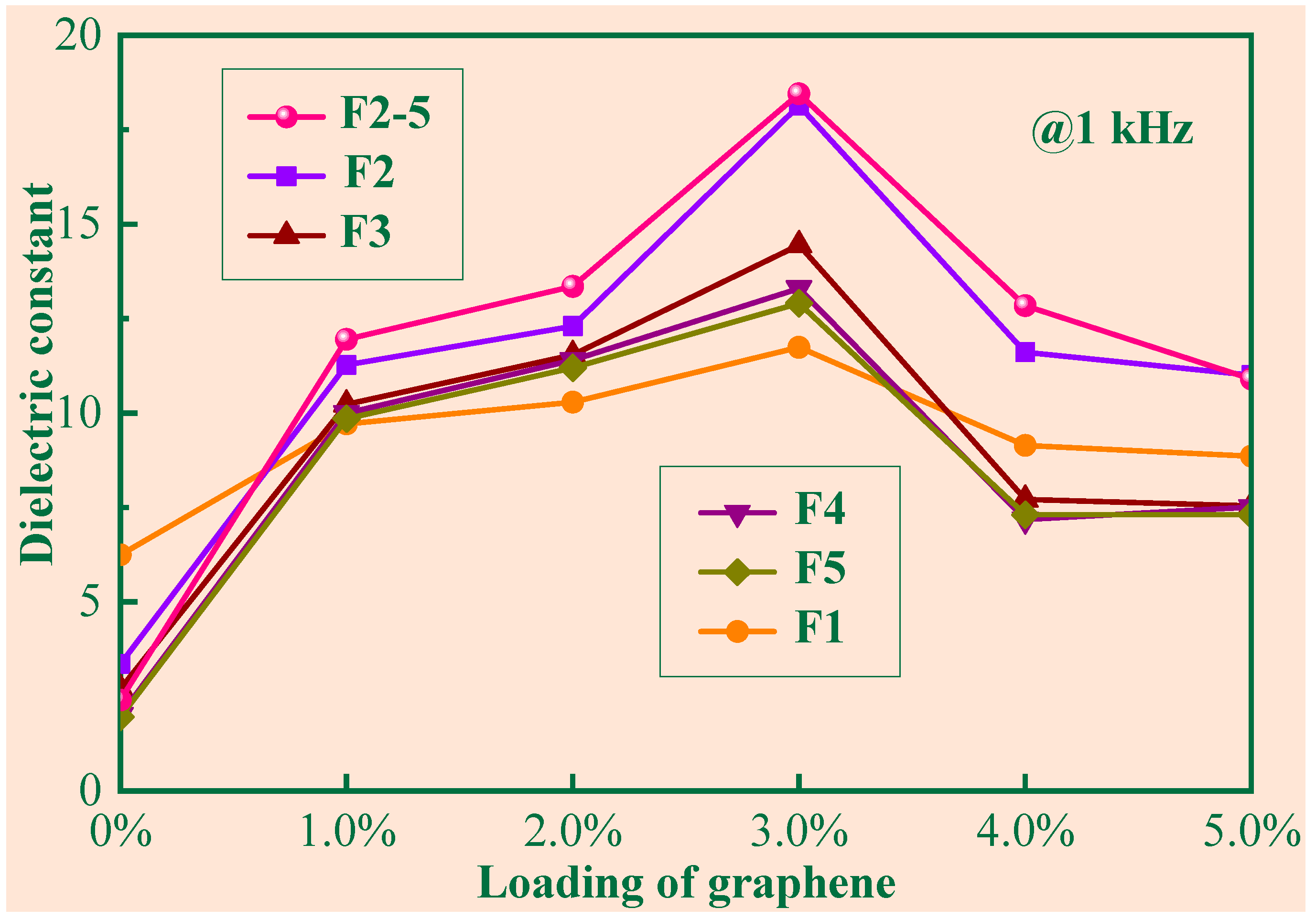
4.2. Dielectric Properties
5. Conclusions
Author Contributions
Funding
Institutional Review Board Statement
Informed Consent Statement
Data Availability Statement
Conflicts of Interest
References
- Liu, C.; Ruan, G.; Wang, P.; Zhou, Y.; Xu, P.; Ding, Y. Synergistic effect of ILs modified MWCNTs on enhanced dielectric properties of silicone rubber/POE blends. Mater. Lett. 2019, 239, 203–206. [Google Scholar] [CrossRef]
- Verdejo, R.; Saiz-Arroyo, C.; Carretero-Gonzalez, J.; Barroso-Bujans, F.; Rodriguez-Perez, M.A.; Lopez-Manchado, M.A. Physical properties of silicone foams filled with carbon nanotubes and functionalized graphene sheets. Eur. Polym. J. 2008, 44, 2790–2797. [Google Scholar] [CrossRef]
- Song, L.; Lu, A.; Feng, P.; Lu, Z. Preparation of silicone rubber foam using supercritical carbon dioxide. Mater. Lett. 2014, 121, 126–128. [Google Scholar] [CrossRef]
- Bai, J.; Liao, X.; Huang, E.; Luo, Y.; Yang, Q.; Li, G. Control of the cell structure of microcellular silicone rubber/nanographite foam for enhanced mechanical performance. Mater. Des. 2017, 133, 288–298. [Google Scholar] [CrossRef]
- Madidi, F.; Momen, G.; Farzaneh, M. Dielectric Properties of TiO2/Silicone Rubber Micro- and Nanocomposites. Adv. Mater. Sci. Eng. 2018, 2018, 4682076. [Google Scholar] [CrossRef]
- Sui, X.; Zhou, W.; Dong, L.; Wang, Z.; Liu, X.; Zhou, A.; Cai, J.; Chen, Q. A novel fiber-reinforced silicone rubber composite with Al particles for enhanced dielectric and thermal properties. Adv. Polym. Technol. 2018, 37, 1507–1516. [Google Scholar] [CrossRef]
- Zhang, L.; Song, F.; Lin, X.; Wang, D. High-dielectric-permittivity silicone rubbers incorporated with polydopamine-modified ceramics and their potential application as dielectric elastomer generator—ScienceDirect. Mater. Chem. Phys. 2020, 241, 122373. [Google Scholar] [CrossRef]
- Zhang, H.; Ma, C.G.; Dai, P.B.; Zhang, J. A reduced graphene oxide–borate compound-loaded melamine sponge/silicone rubber composite with ultra-high dielectric constant. RSC Adv. 2019, 9, 14276–14285. [Google Scholar] [CrossRef] [PubMed]
- Li, Y.; Li, M.; Pang, M.; Zhang, J.; Zhang, C. Effects of multi-walled carbon nanotube structures on the electrical and mechanical properties of silicone rubber filled with multi-walled carbon nanotubes. J. Mater. Chem. C 2015, 3, 5573–5579. [Google Scholar] [CrossRef]
- Sharika, T.; Vijayan, P.P.; Xavier, P.; Bose, S.; Thomas, S. Selective localisation of multi walled carbon nanotubes in polypropylene/natural rubber blends to reduce the percolation threshold. Compos. Sci. Technol. 2015, 116, 9–17. [Google Scholar]
- Yang, J.; Liao, X.; Li, J.; He, G.; Li, G. Light-weight and flexible silicone rubber/MWCNTs/Fe3O4 nanocomposite foams for efficient electromagnetic interference shielding and microwave absorption. Compos. Sci. Technol. 2019, 181, 107670. [Google Scholar] [CrossRef]
- Chen, Q.; Zhao, J.; Ren, J.; Rong, L.; Cao, P.F.; Advincula, R.C. 3D Printed Multifunctional, Hyperelastic Silicone Rubber Foam. Adv. Funct. Mater. 2019, 29, 1900469. [Google Scholar] [CrossRef]
- Xiang, B.; Deng, Z.; Zhang, F.; Wen, N.; Lei, Y.; Liu, T.; Luo, S. Microcellular silicone rubber foams: The influence of reinforcing agent on cellular morphology and nucleation. Polym. Eng. Sci. 2019, 59, 5–14. [Google Scholar] [CrossRef]
- Wei, C.S.; Lu, A.; Sun, S.M.; Wei, X.W.; Zhou, X.Y.; Sun, J. Establishment of Constitutive Model of Silicone Rubber Foams Based on Statistical Theory of Rubber Elasticity. Chin. J. Polym. Sci. 2018, 36, 1077–1083. [Google Scholar] [CrossRef]
- Liu, M.; Yu, L.; Vudayagiri, S.; Skov, A.L. Incorporation of liquid fillers into silicone foams to enhance the electro-mechanical properties. Int. J. Smart Nano Mater. 2020, 11, 11–23. [Google Scholar] [CrossRef]
- Xu, X.; Park, C.B.; Xu, D.; Pop-Iliev, R. Effects of die geometry on cell nucleation of PS foams blown with CO2. Polym. Eng. Sci. 2004, 43, 1378–1390. [Google Scholar] [CrossRef]
- Matuana, L.M.; Park, C.B.; Balatinecz, J.J. Processing and cell morphology relationships for microcellular foamed PVC/wood-fiber composites. Polym. Eng. 1997, 37, 1137–1147. [Google Scholar] [CrossRef]
- Hu, Q. The Properties of Polystyrene/Graphene Nanocomposites Microcellular Foam Using Supercritical Carbon Dioxide. Master’s Thesis, Beijing University of Chemical Technology, Beijing, China, 2014. [Google Scholar]
- Bilent, S.; Dinh, N.T.H.; Martincic, E.; Joubert, P.-Y. Influence of the Porosity of Polymer Foams on the Performances of Capacitive Flexible Pressure Sensors. Sensors 2019, 19, 1968. [Google Scholar] [CrossRef] [PubMed]
- Mclachlan, D.S.; Blaszkiewicz, M.; Newnham, R.E. Electrical Resistivity of Composites. J. Am. Ceram. Soc. 1990, 73, 2187–2203. [Google Scholar] [CrossRef]
- Hu, N.; Karube, Y.; Yan, C.; Masuda, Z.; Fukunaga, H. Tunneling effect in a polymer/carbon nanotube nanocomposite strain sensor. Acta Mater. 2008, 56, 2929–2936. [Google Scholar] [CrossRef]
- Ameli, A.; Nofar, M.; Park, C.B.; Pötschke, P.; Rizvi, G. Polypropylene/carbon nanotube nano/microcellular structures with high dielectric permittivity, low dielectric loss, and low percolation threshold. Carbon 2014, 71, 206–217. [Google Scholar] [CrossRef]
- Zhao, B.; Hamidinejad, M.; Zhao, C.; Li, R.; Wang, S.; Kazemi, Y.; Park, C.B. A versatile foaming platform to fabricate polymer/carbon composites with high dielectric permittivity and ultra-low dielectric loss. J. Mater. Chem. A 2019, 7, 133–140. [Google Scholar] [CrossRef]
- Gao, Y.; Wang, C.; Li, J.; Guo, S. Adjustment of dielectric permittivity and loss of graphene/thermoplastic polyurethane flexible foam: Towards high microwave absorbing performance. Compos. Part A Appl. Sci. Manuf. 2019, 117, 65–75. [Google Scholar] [CrossRef]


| Foams | Mass Ratio | α |
|---|---|---|
| F1 | HY-F661A:HY-F661B = 1:1 | 1 |
| F2 | HY-F662A:HY-F662B = 1:1 | 2 |
| F3 | HY-F663A:HY-F663B = 1:1 | 3 |
| F4 | HY-F664A:HY-F664B = 1:1 | 4 |
| F5 | HY-F665A:HY-F665B = 1:1 | 5 |
| F2-5 | HY-662A:HY-662B:HY-665A:HY-665B = 1:1:1:1 | 3.5 |
| Sample | F1 | F2 | F3 | F4 | F5 | F2-5 |
|---|---|---|---|---|---|---|
| Void fraction f (%) | 0 | 50 | 66.7 | 75 | 80 | 71.4 |
| Average cell size (μm) | 191 | 182 | 148 | 79.4 | 143 | |
| Cell number | 71 | 90 | 115 | 149 | 155 | |
| <50 μm | 0 | 1 | 5 | 34 | 5 | |
| 50–100 μm | 8 | 11 | 26 | 81 | 38 | |
| 100–150 μm | 11 | 20 | 31 | 24 | 58 | |
| 150–200 μm | 21 | 21 | 26 | 10 | 25 | |
| 200–250 μm | 19 | 22 | 19 | 0 | 14 | |
| >250 μm | 12 | 15 | 8 | 0 | 15 | |
| Large cell (>150 μm) | 73.24% | 64.44% | 46.09% | 6.71% | 34.84% | |
| Cell density (105/cm3) | 2.13 | 3.36 | 5.49 | 7.15 | 6.07 |
| Foams | Void fraction f (%) | Theoretical εr | Experimental εr |
|---|---|---|---|
| F1 | 0 | 6.25 | 6.25 ± 0.25 |
| F2 | 50 | 3.63 | 3.36 ± 0.31 |
| F3 | 66.7 | 2.75 | 2.62 ± 0.10 |
| F4 | 75 | 2.31 | 1.96 ± 0.32 |
| F5 | 80 | 2.05 | 1.67 ± 0.28 |
Publisher’s Note: MDPI stays neutral with regard to jurisdictional claims in published maps and institutional affiliations. |
© 2022 by the authors. Licensee MDPI, Basel, Switzerland. This article is an open access article distributed under the terms and conditions of the Creative Commons Attribution (CC BY) license (https://creativecommons.org/licenses/by/4.0/).
Share and Cite
Jia, F.; Liu, C.; Yang, B.; Lee, A.; Wu, L.; Ning, H. Preparation of Novel Graphene/Silicone Rubber Nanocomposite Dielectric Foams. Polymers 2022, 14, 3273. https://doi.org/10.3390/polym14163273
Jia F, Liu C, Yang B, Lee A, Wu L, Ning H. Preparation of Novel Graphene/Silicone Rubber Nanocomposite Dielectric Foams. Polymers. 2022; 14(16):3273. https://doi.org/10.3390/polym14163273
Chicago/Turabian StyleJia, Fei, Cong Liu, Bo Yang, Alamusi Lee, Liangke Wu, and Huiming Ning. 2022. "Preparation of Novel Graphene/Silicone Rubber Nanocomposite Dielectric Foams" Polymers 14, no. 16: 3273. https://doi.org/10.3390/polym14163273
APA StyleJia, F., Liu, C., Yang, B., Lee, A., Wu, L., & Ning, H. (2022). Preparation of Novel Graphene/Silicone Rubber Nanocomposite Dielectric Foams. Polymers, 14(16), 3273. https://doi.org/10.3390/polym14163273