2.1. Preliminary Research—Mechanical Performance of Innovative Hollow Glue-Laminated Timber Beams
This research is a continuation and improvement of investigations previously done by Perkovic et al. [
23]. It concerns timber elements whose cross-section has been perforated in order to have less mass. Furthermore, this greatly facilitates the manipulation of individual elements that can be assembled into walls and ceilings. On top of all that, the remains of the perforated elements are recycled and used further for various purposes, which ensures and maintains global energy stability and reduces carbon production. The material characteristics of the samples were the same as in the previous research. The elements were made of softwood with the predominant use of European fir (Abies alba). In previous work, the basic conclusions about the behavior of these innovative elements were made, and the shortcomings and recommendations for further research were identified. Primarily, they concern the type of hole (circular or elliptical), the arrangement of the lamellae and hollows, and finally, the adhesive used in joining the lamellae. Consequently, the conclusion was that samples with elliptical holes have higher and satisfactory load capacity. Furthermore, moisture-curing 1-component polyurethane adhesive PUR Kleiberit 510.0 with reinforced fibers [
24] was used for the research, and the edge lamellas were made without holes, to avoid stress concentration in the edge zones. According to DIN EN 14,080 and DIN EN 15,497, this is a one-component certified PUR adhesive for load-carrying wood construction. It is approved according to SANS 10183-2 as a wood adhesive for load-carrying wood components in service class S3 (service class S3), which means that is suitable for long-term outdoor use, even with direct contact with the ground. New, improved timber elements used in this paper can be seen in
Figure 2.
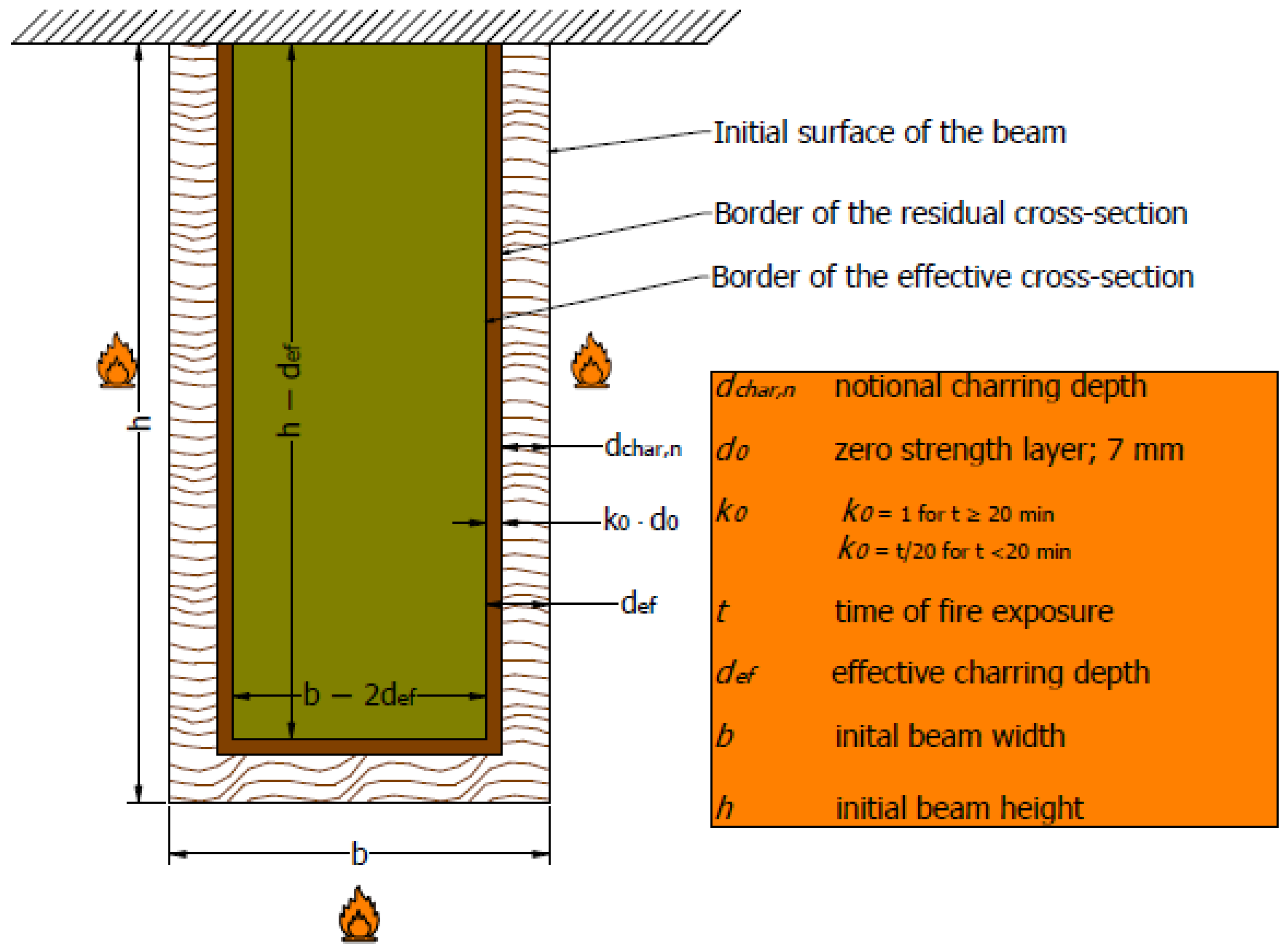
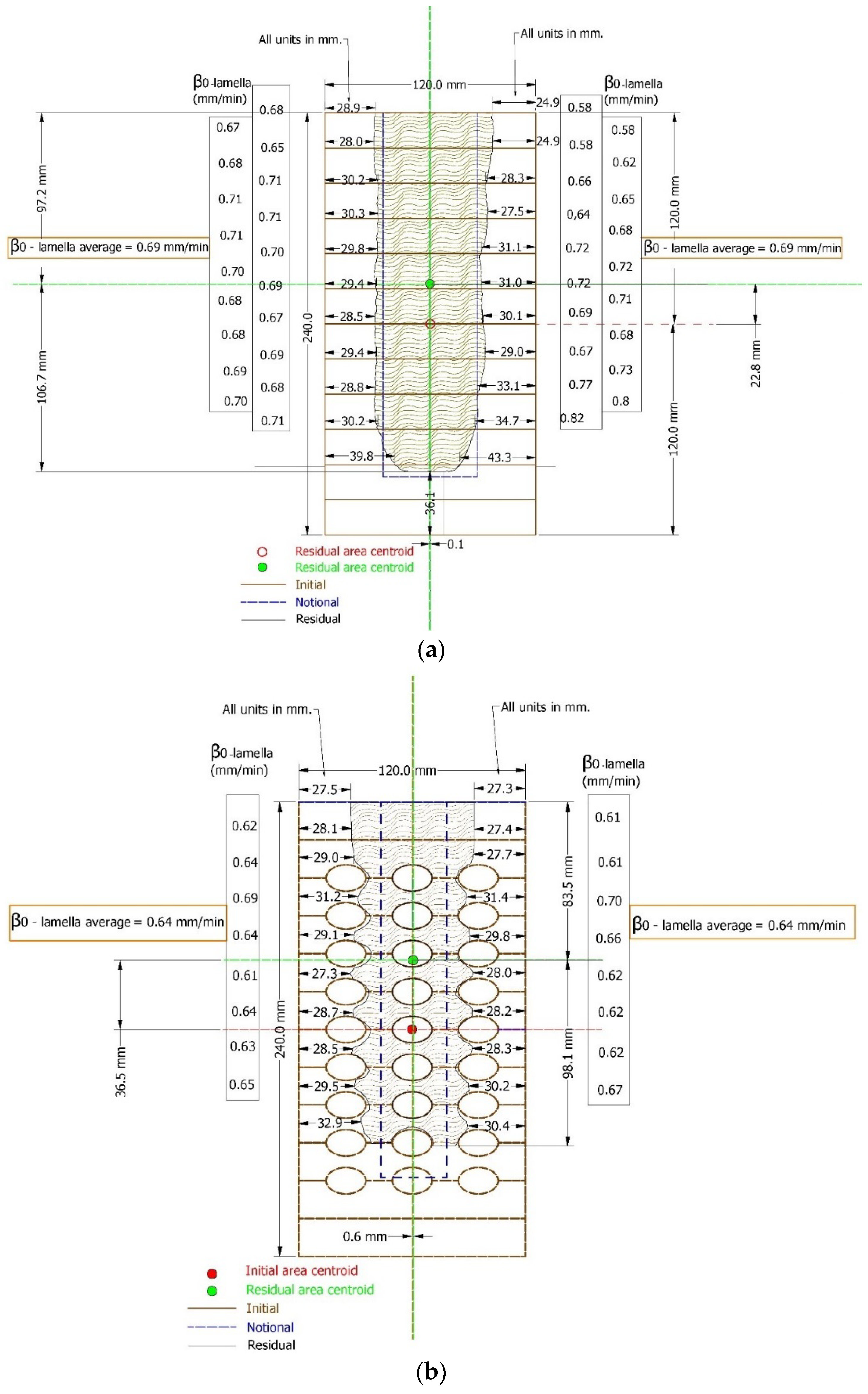
The fire resistance time for a normal GL timber beam can be estimated by defining the ideal residual cross-section (
Figure 3) according to EN 1995-1-2 [
25], and comparing the actual bending stress, which depends on the residual cross-section values at a given time:
The values for β
n, k
0, and d
0 are taken from Eurocode 5 (EN 1995-1-2, 2004) [
25]:
The acting moment depends on the load level m
u,fi related to the bending moment resistance at normal temperature:
This means the fire resistance does not depend on the bending strength but the load level factor.
The applied load level in the fire test needs to be defined before the test. Time is the only unknown parameter remaining in the inequality, which means it can easily be computed for each load level. In this research, the load is defined respecting the serviceability limit state, i.e., the maximal allowable deflection L/300, which for this specific case is 14.4 mm. This corresponds to approximately 30% of the failure load at ambient temperature, which is the load level proposed by many researchers [
26].
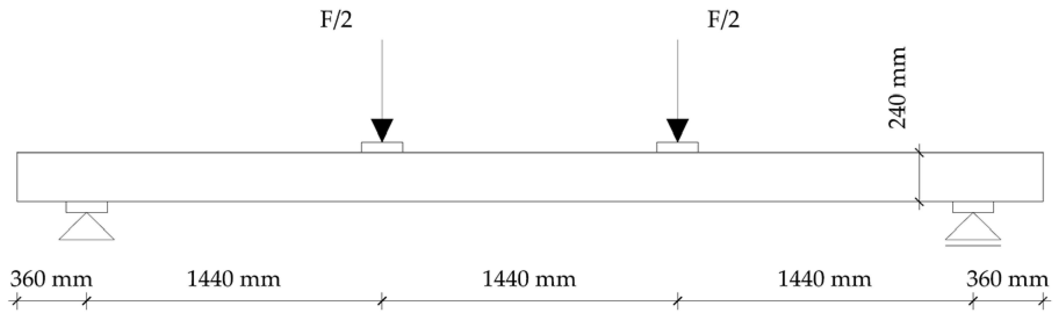
To determine the load level for the fire test, four-point bending tests on timber elements were carried out according to EN 408 [
27]. The tests were carried out on a simply supported beam with a span of 18 h, where h is the height of the sample. The distance of the load input from the support and the distance between the forces themselves was 6 h (
Figure 4). To avoid local stresses, additional steel plates were placed at the point of load application. In this way, the correct load distribution on the sample was obtained.
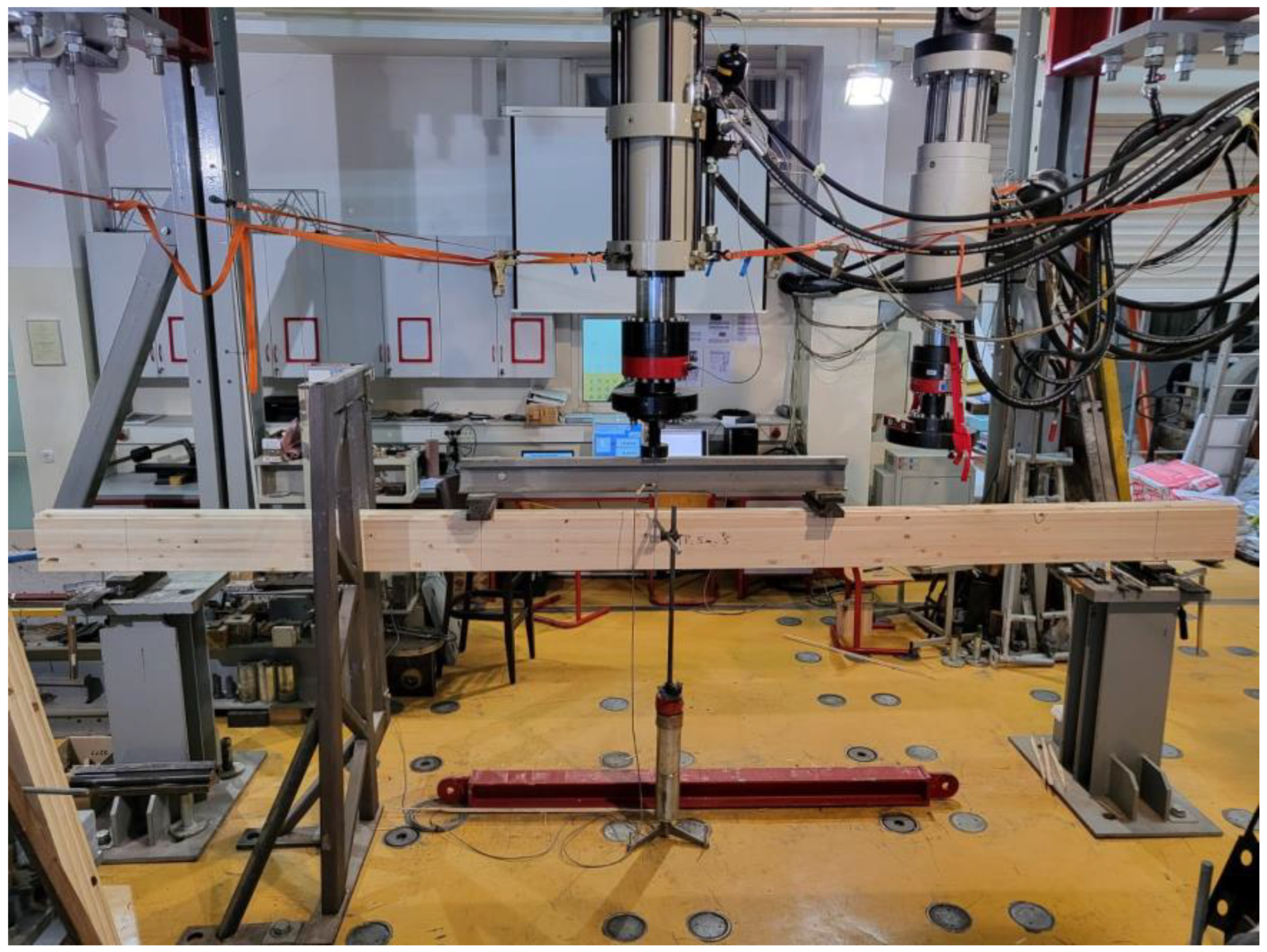
For the experimental investigation in ambient temperature, a dynamic–static universal machine from Zwick Roell GmBH Test & Co., KG, Ulm, Germany was used. The maximum force on the machine is 250 kN, class 1, which represents a deviation of 1. Furthermore, MGC plus data acquisition system (manufacturer HBM—Hottinger Baldwin Messtechnik, Germany) was used. Following EN 408 and the required failure time, the displacement rate was defined and thus the load on the sample was defined. According to EN 408, failure load should occur at (300 ± 120) s. Consequently, the test speed was defined to be 6 mm/min. In this experimental research, six basic values were measured, including time, deflection on supports and in the middle span, piston displacement, and load. Linear variable differential transformers with a sensitivity of 10 mm (supports) and 100 mm (midspan) were used to measure the displacement. Given the geometry of the sample and the fact that the end lamellae were shaped in such a way that there were notches, it was necessary to introduce additional auxiliary elements in the form of caps, over which the load was applied. For this purpose, additional timber elements were made and positioned at the load input area. These additional elements were made of a more solid material to prevent local embossing. The clamps were installed at the support in order to simulate lateral restraints. The experimental work and setup are shown in
Figure 5.
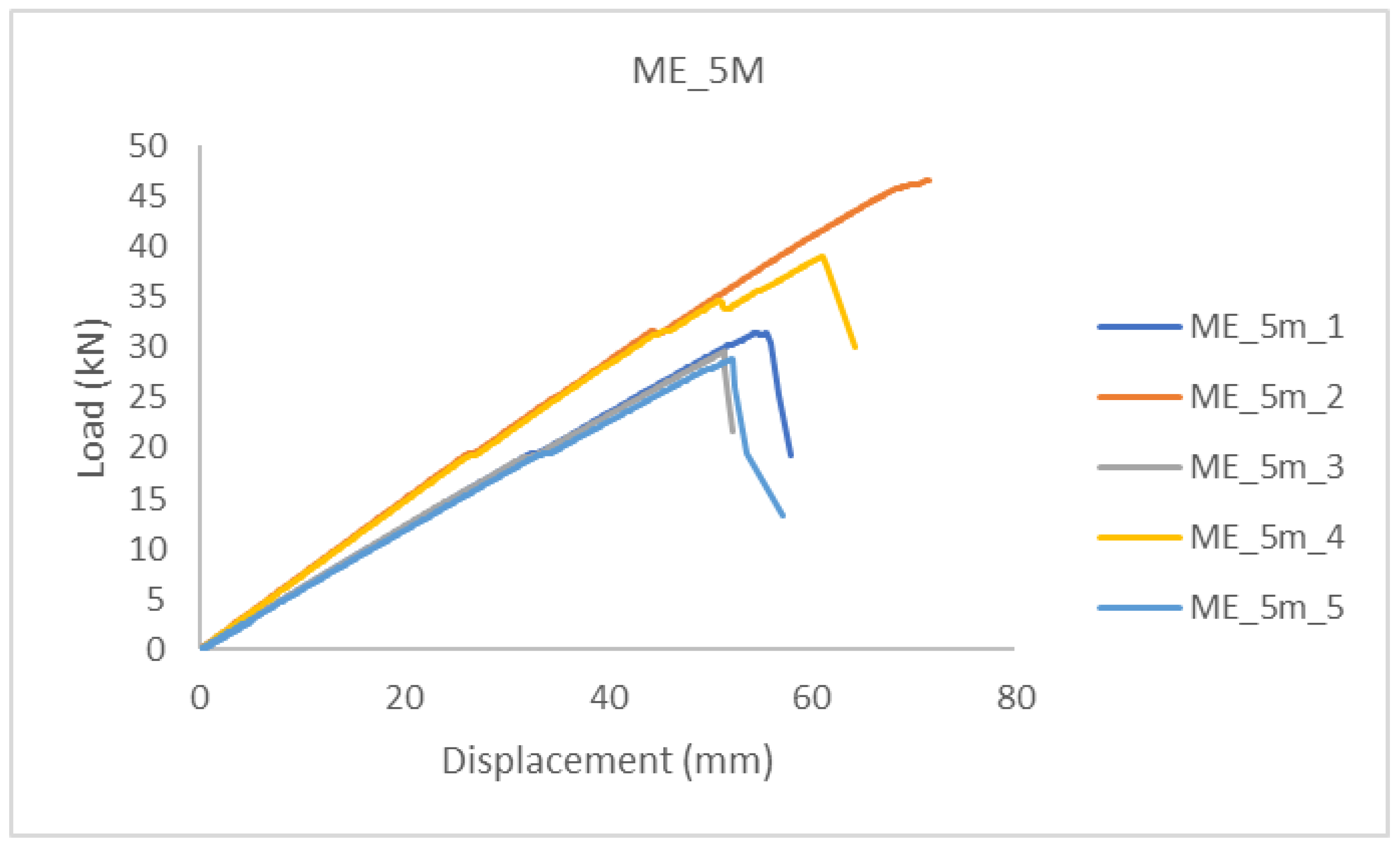
In the diagrams shown below (
Figure 6 and
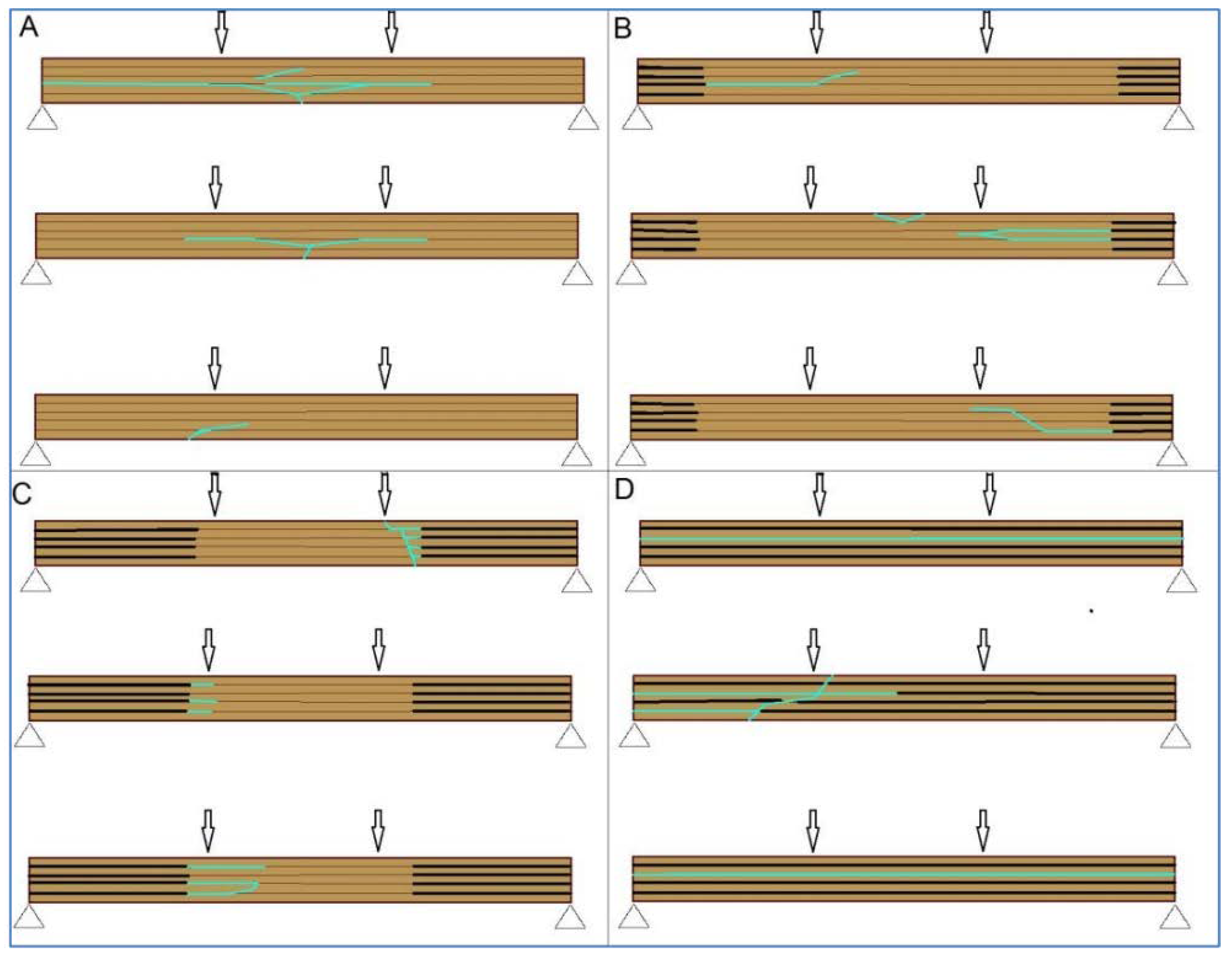
Figure 7), it can be seen that the beams (in the same sample group), up to a certain load level showed similar behavior, i.e., stiffness. For higher load levels, their stiffness was significantly reduced due to local wood imperfections, cracking, and adhesive behavior. The failure occurred after reaching the tensile strength of the timber.
Timber beams with ellipse-shaped cavities marked ME_5m-n, and normal (without cavities) marked MP_5m_n, were tested, where “n” represents the number of the tested specimen.
The linear behavior of the elements can be seen in the diagrams, after which a brittle fracture occurred. Furthermore, a minimal force reduction is observed in the diagrams, indicating the cracking of a particular lamella or grain. After that, the force increases again until the fracture of the next grain, and so on, until the complete fracture of the sample occurs when it reaches its tensile strength (
Figure 6 and
Figure 7).
The higher slope of the force-displacement curve for normal MP-n specimens can be seen in
Figure 6, which indicates their greater stiffness, which is natural considering the perforation of the ME-n specimens, i.e., the smaller cross-sectional area.
A comparison of the results can be seen in
Table 1 and
Table 2. It can be concluded that the load-bearing capacity of the hollow GL timber specimens was reduced by 35% compared to the normal GL timber specimens.
In
Figure 7, it can be seen that the failure of samples with the same type of cavities did not occur at the same load value. The cause was mostly natural wood defects, such as knots, shakes, cross-grain, crookedness, rind galls, burrs, and curls.
2.2. Fire Tests
This article contains the results of a fire test of glue-laminated normal and hollow timber beams in accordance with the procedures of the reference standards EN 1363-1:2020 [
28] and HRN EN 1365-3:2002 [
29].
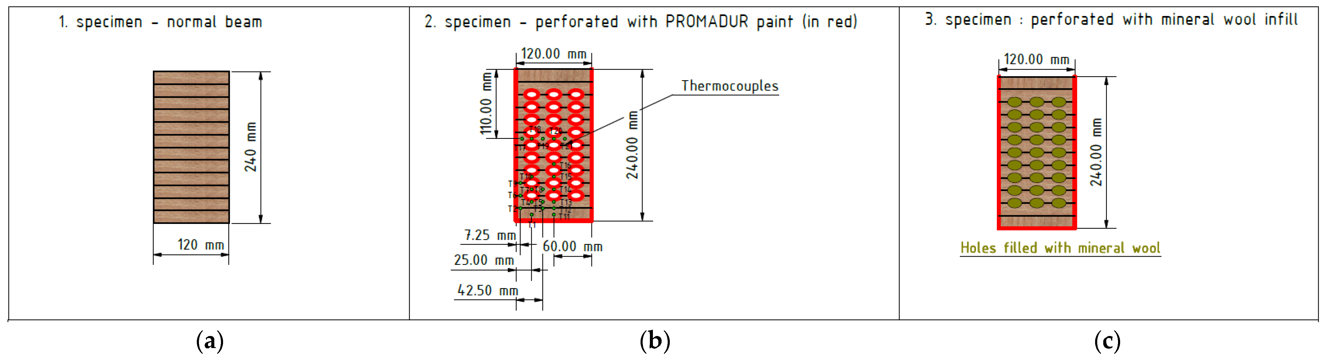
The dimensions of the samples were the same as in the mechanical tests, as follows: 120 × 240 × 5040 mm (width × height × length). Moisture was measured in each sample and the average moisture was 10% for all samples. The laminated timber sample consisted of a total of twelve lamellae glued together. The slats were made of soft timber (fir) 20 mm thick and made in such a way that the fibers inside the timber were directed in the direction of the length of the beam (see
Figure 8 and
Figure 9). The lamellas were glued using Kleiberit 510.0 glue, manufactured by Klebchemie-M.G. Becker GmbH [
24]. This is a PUR adhesive for load-bearing wood construction certified in accordance with DIN 1052 [
30]. An advantage and difference compared to previous research [
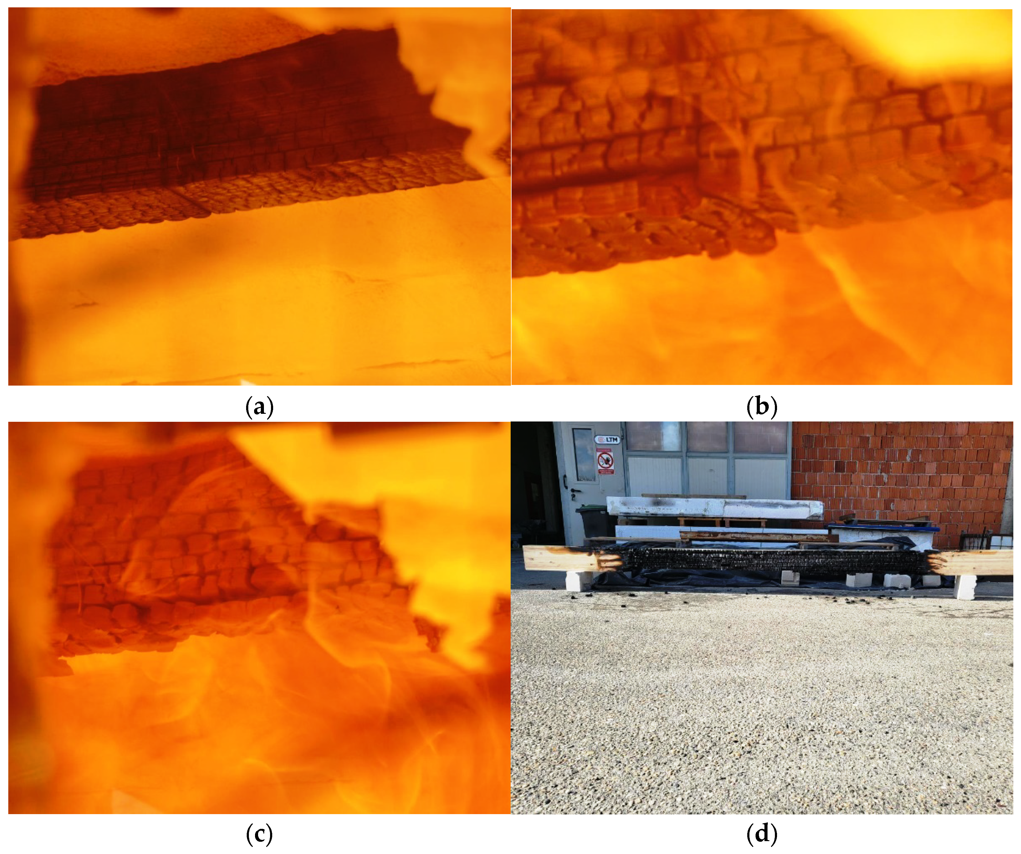
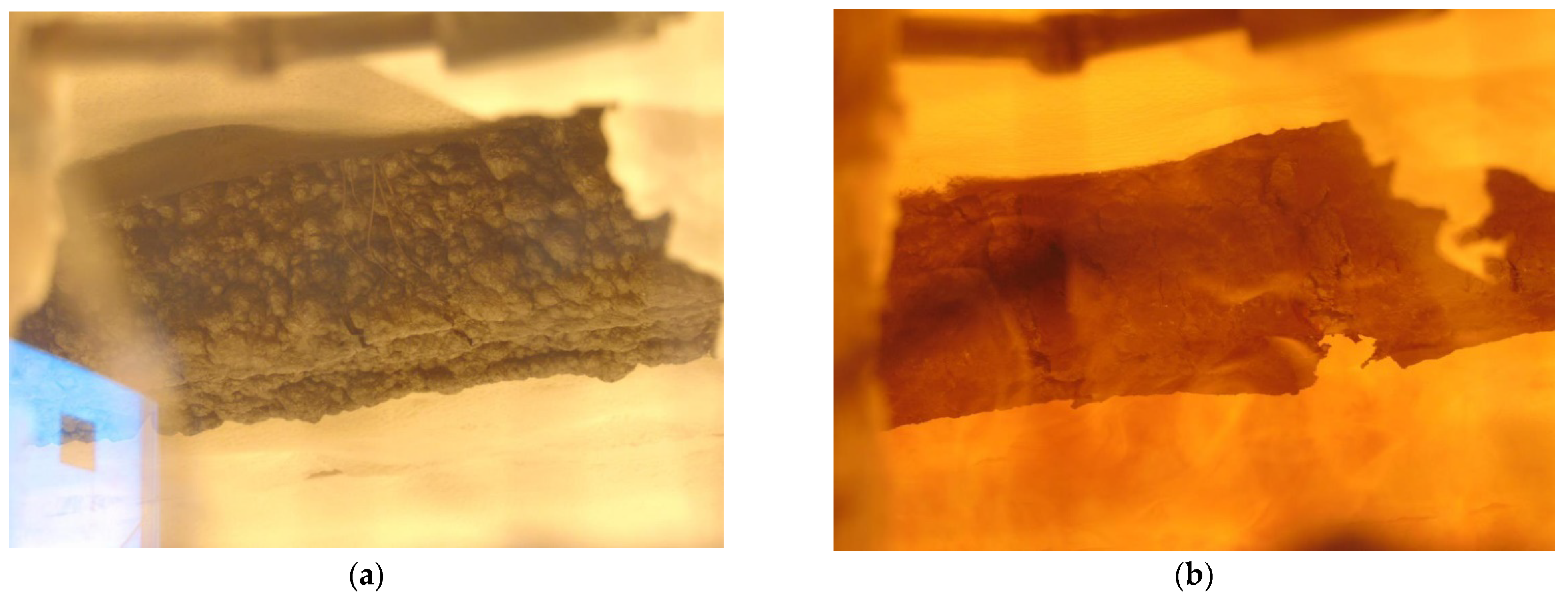
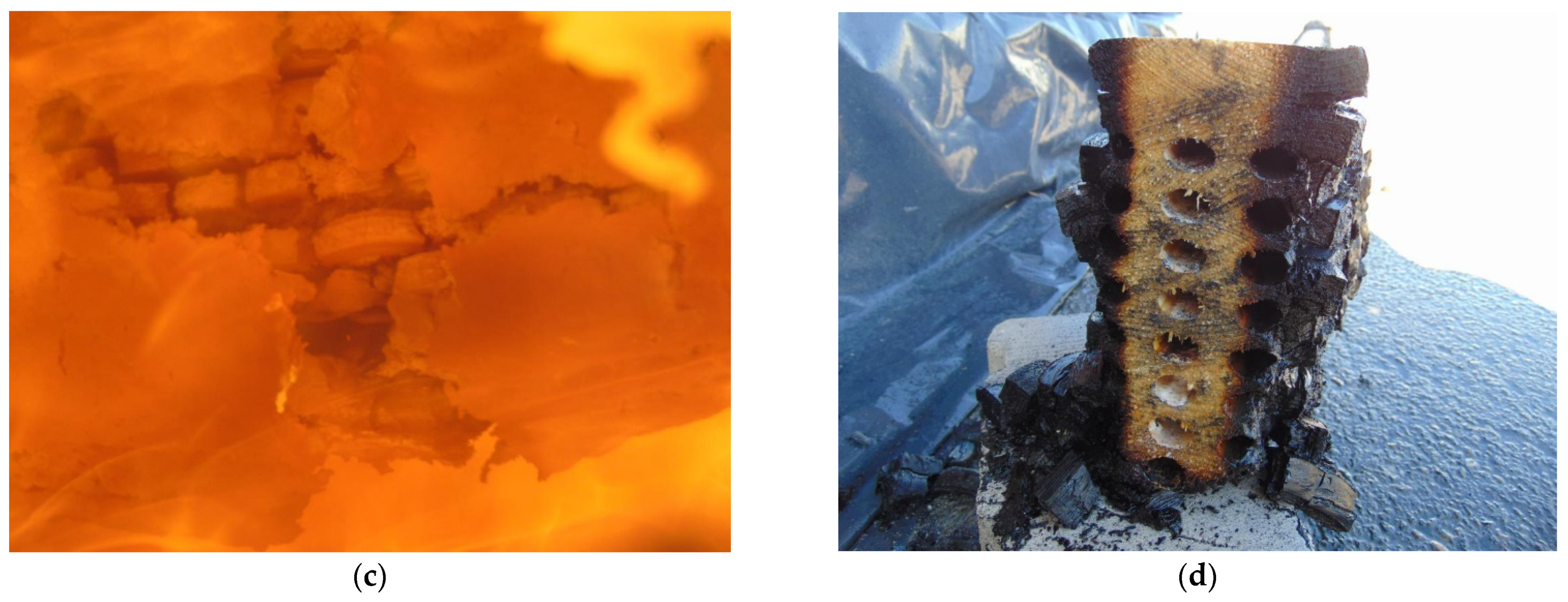
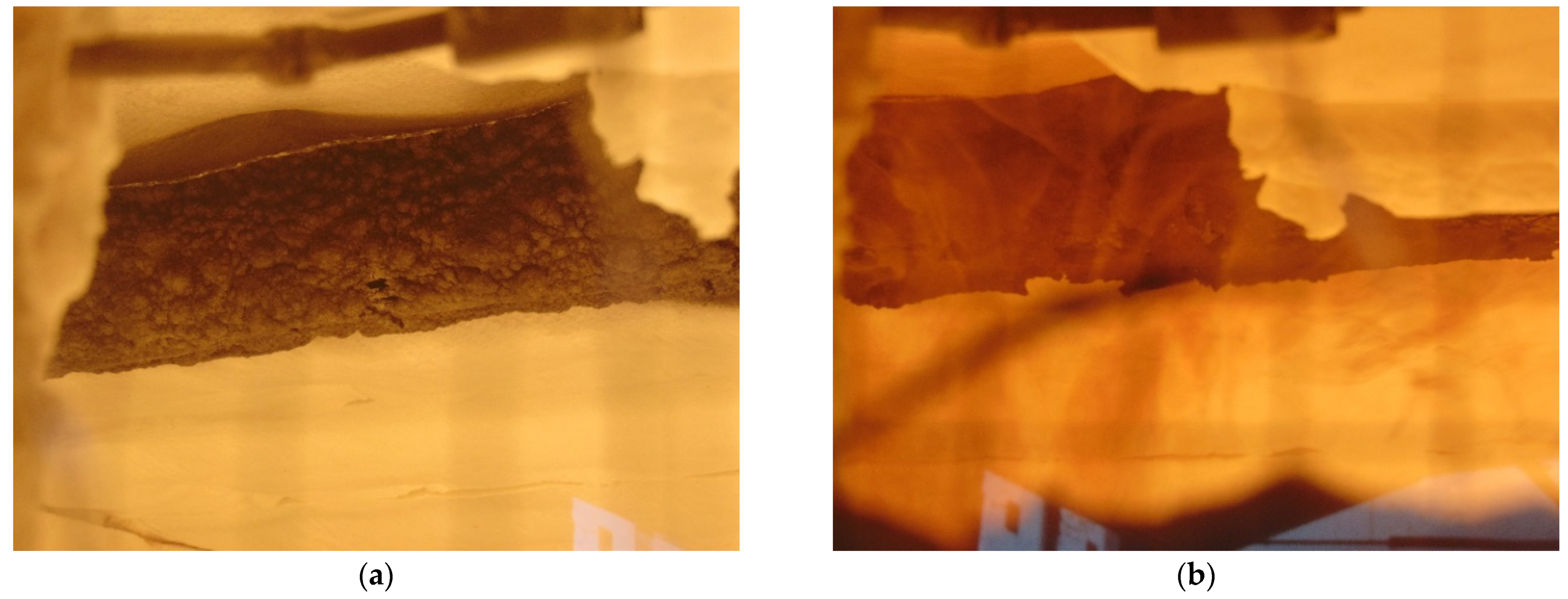
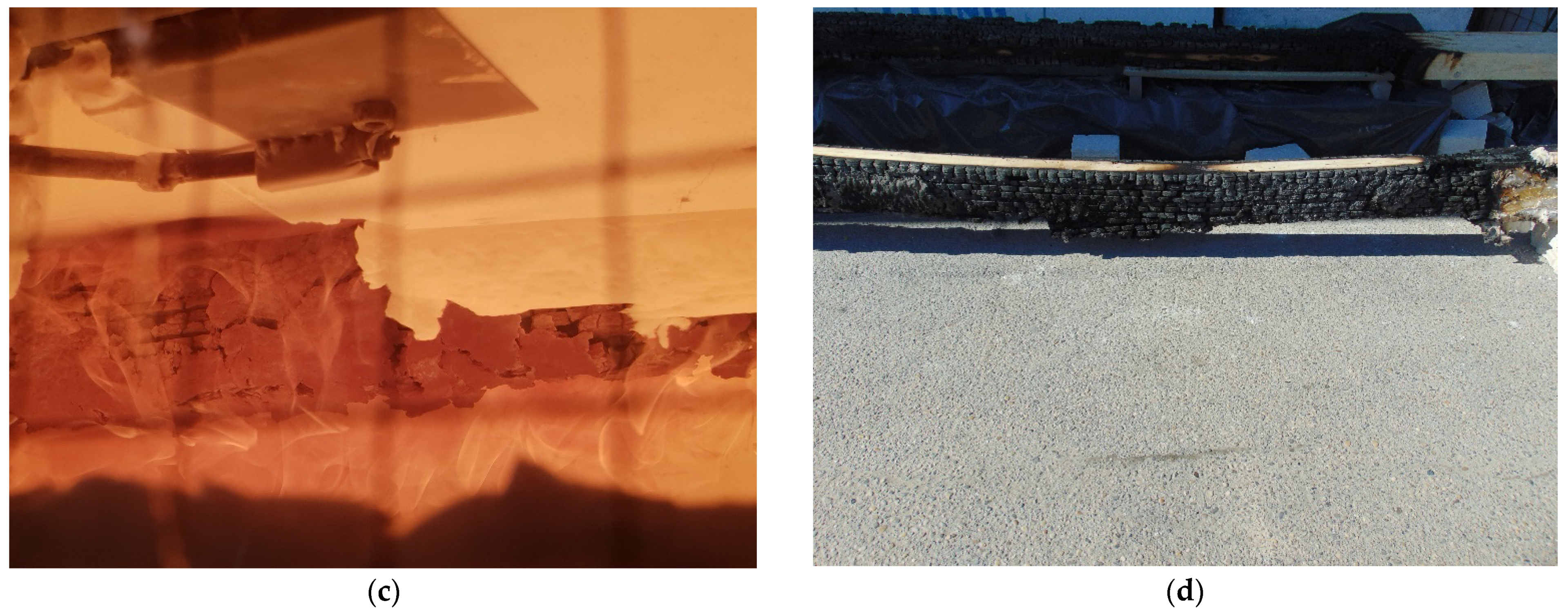
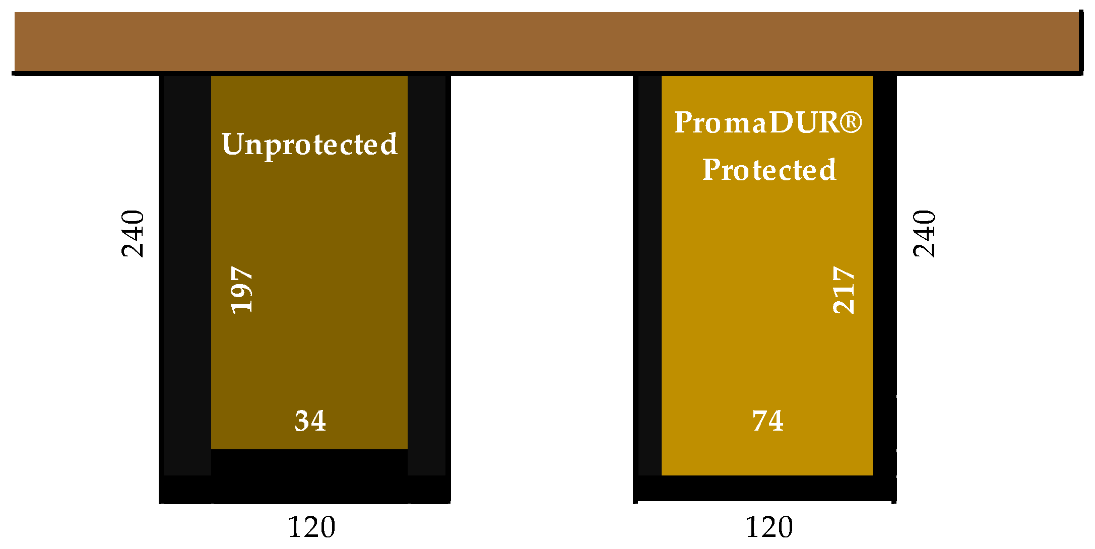
23] was that this adhesive has a very high bond strength due to specially reinforced fibers. Three different types of timber beams were tested to compare innovative hollow glue-laminated timber elements with standard and most used timber products. Therefore, the first sample was a standard GL timber beam, and the other two were hollow GL beams with fire protection. In the first hollow beam, the protection was an intumescent paint coating, Promadur [
31], along the perimeter of the beam and inside the cavity, while in the second the mineral wool was placed in cavities and intumescent paint was also applied on the outer surface of the sample. In this research, PROMADUR [
31] intumescent paint was used. It is a single-pack water-borne, solvent-free transparent intumescent coating for fire protection of timber structures. In the case of fire, PROMADUR expands, creating a protective insulating foam that protects the substrate from contact with air (oxygen), decreasing the combustibility, and slowing down the transfer of energy (heat) from the fire to the timber elements, increasing the fire resistance. The general idea was to use cavities in such a way as to partially stop the penetration of fire and temperature towards the interior of the beam.
Figure 8 shows different types of cross-sections of investigated timber beams.
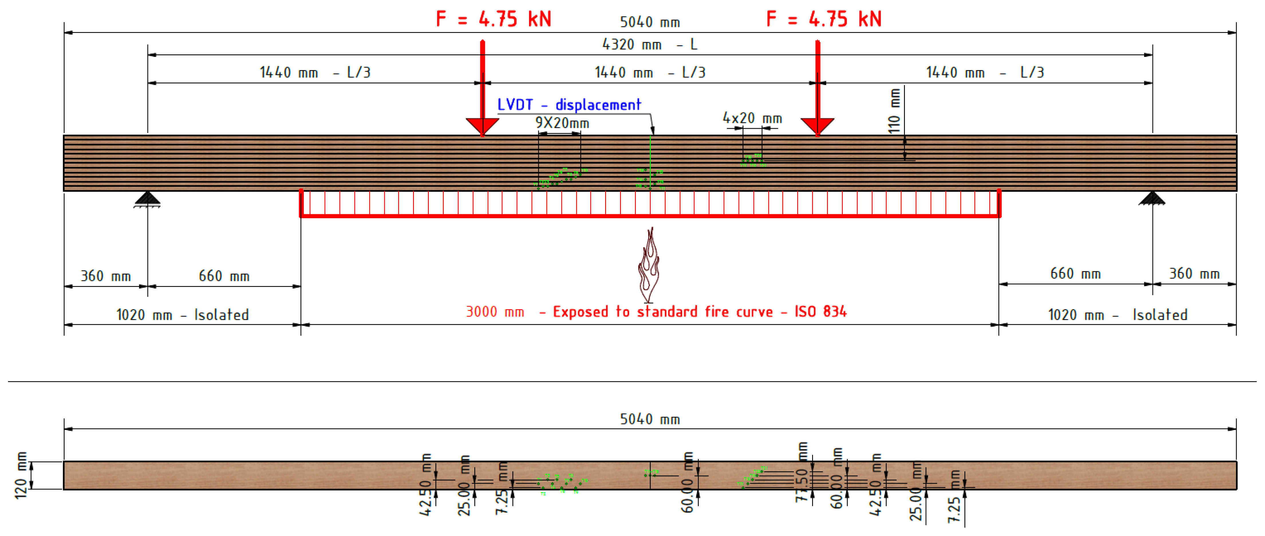
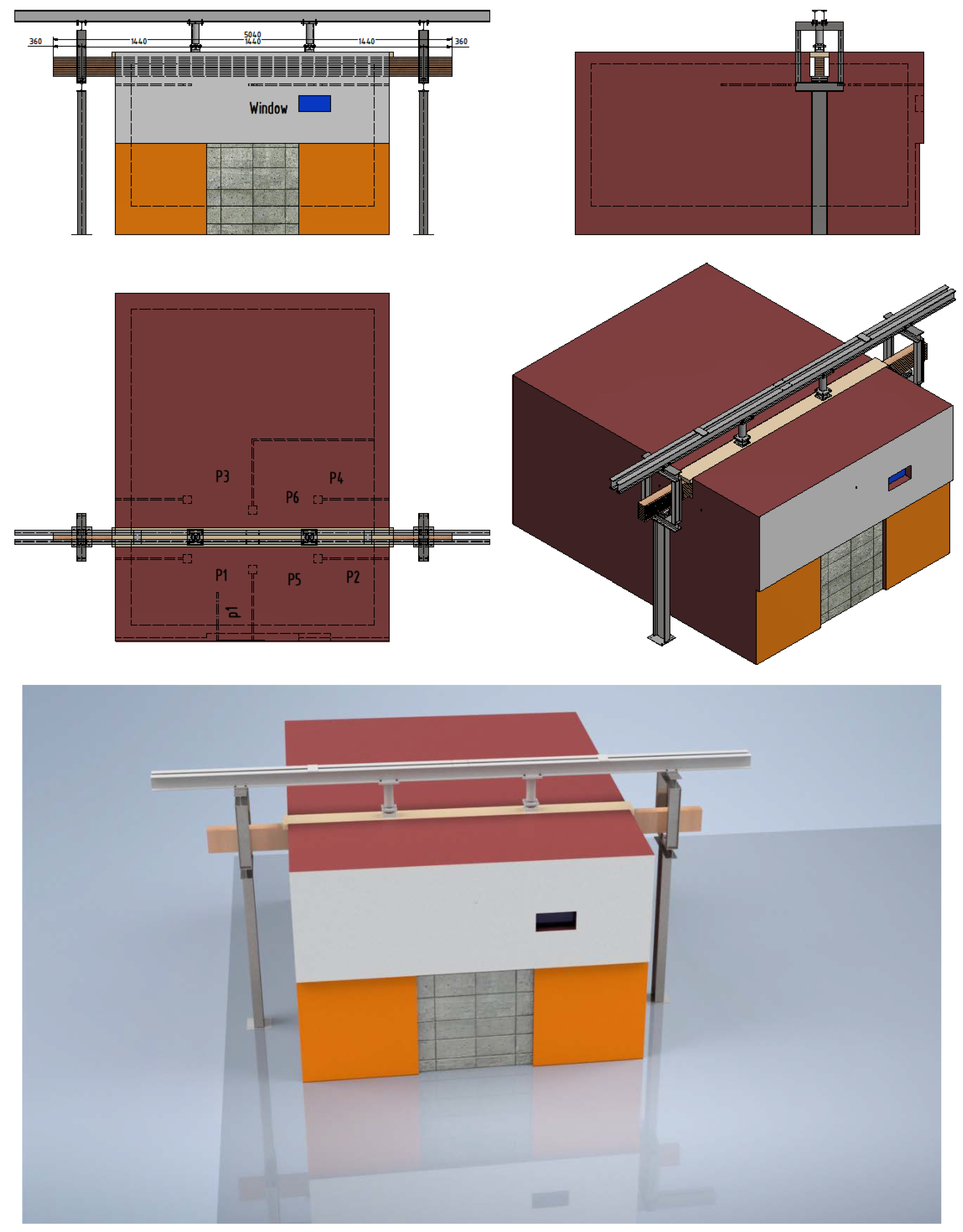
The samples were exposed to fire on three sides (bottom and sides). The load-bearing beam specimen was mounted on a vertical load-bearing structure equipped with a hydraulic system for applying the load. The load-bearing structure was placed on the horizontal test furnace in such a way that only a part of the beam 3000 mm long was exposed to fire. The beam was oriented so that the longer side of the section (240 mm) was placed vertically. The beam supports were located outside the test furnace at a distance of 4320 mm from each other. On one side of the beam, one support was fixed, and on the other side, it was sliding in the longitudinal direction. All the above described can be seen in
Figure 9.
The ceiling of the furnace was made using 150 mm-thick aerated concrete floor slabs. In the central part of the furnace, a 320 mm-wide opening was left between them, inside which a sample was installed. In this way, fire exposure from three sides of the sample was enabled. A 40 mm-thick calcium silicate plate of sufficient strength was placed on the upper surface of the sample to allow a load to be applied across it. The plate was of such width as to close the opening in the ceiling of the test furnace. The gap between the sample and the edges of the test furnace was closed with ceramic wool.
The construction, composition, and orientation of the sample as well as the type of sample supports on the load-bearing structure, are shown in
Figure 10.
Prior to installation, the test sample was placed in a laboratory where the ambient conditions were maintained at approximately 50% relative humidity and 20 °C, in accordance with HRN EN 1363-1: 2020, clause 8.1 [
28].
The percentage of moisture retained in the sample was measured immediately before the test and was 12.7%.
The fire furnace allowed standard exposure of test specimens to fire with respect to heat exposure and pressure. The fire in the fire area of the furnace was realized by means of six burners on liquid fuel (heating oil), in accordance with the standard HRN EN 1363-1: 2020, chapters 4.1 and 4.2 [
28]. Air temperature in the test room 24 h before the fire test was maintained at 20 (±5) °C. Furnace heating was determined by a standard temperature curve, in accordance with the standard HRN EN 1363-1: 2020, 5.1 [
28] and defined according to the following formula:
where T is the average temperature in the furnace (°C), and t is time (min.)
The temperature in the furnace was measured with six thermocouples of type K, whose hot joint was fixed in the geometric center of the plate in accordance with the standard HRN EN 1363-1: 2020, 4.5.1.1 [
28].
The thermocouples were evenly distributed along with the test sample and positioned so that they were not in contact with the open flame from the burner and were 100 mm away from the fire-exposed side of the test sample.
Static pre-pressure in the fire chamber of the test furnace was maintained in the range of 15 ± 3 Pa. The sensor-pressure gauge was placed so that the pressure was measured 100 mm below the level of the installed test sample and regulated by the closing part of the main and unloading chimney of the furnace.
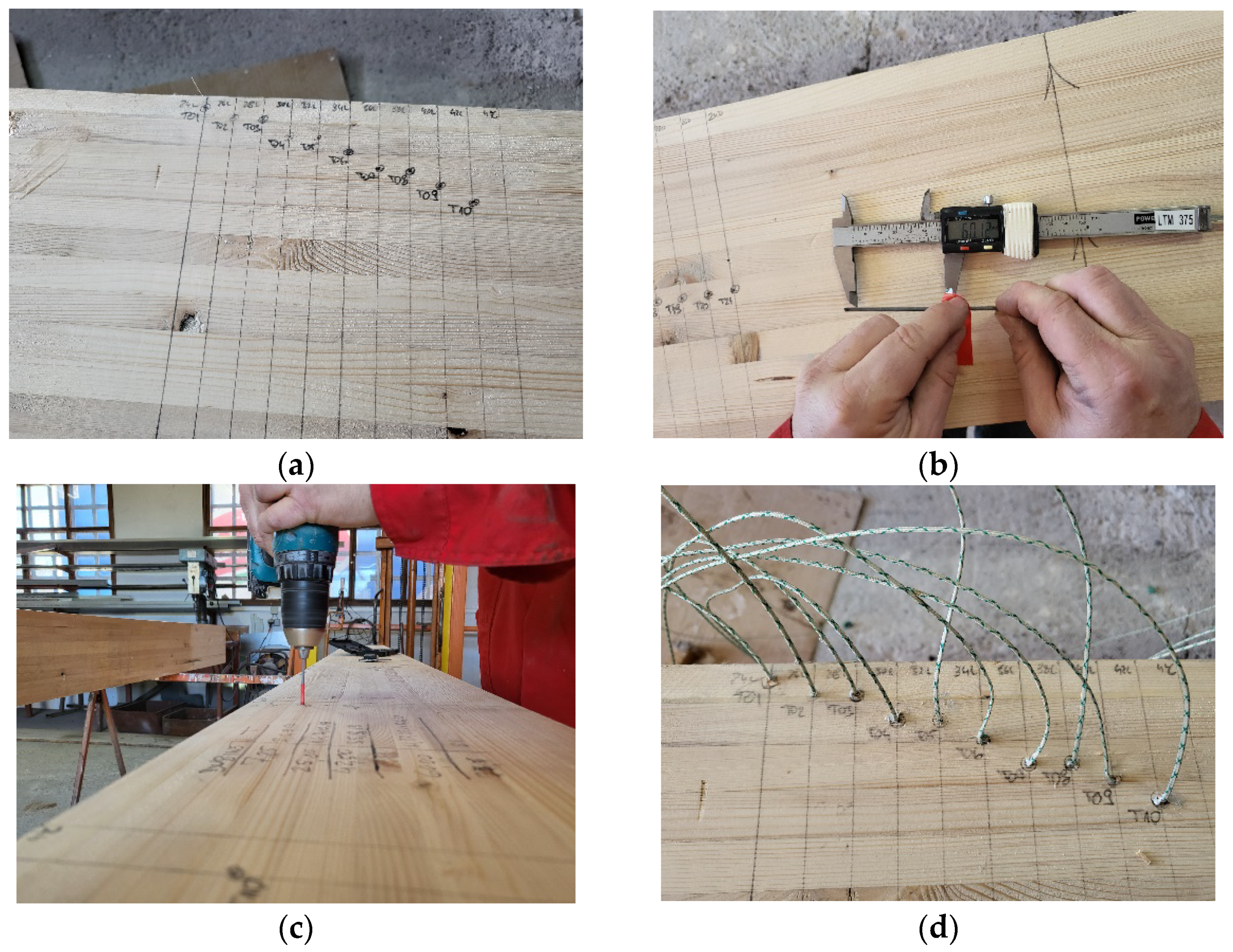
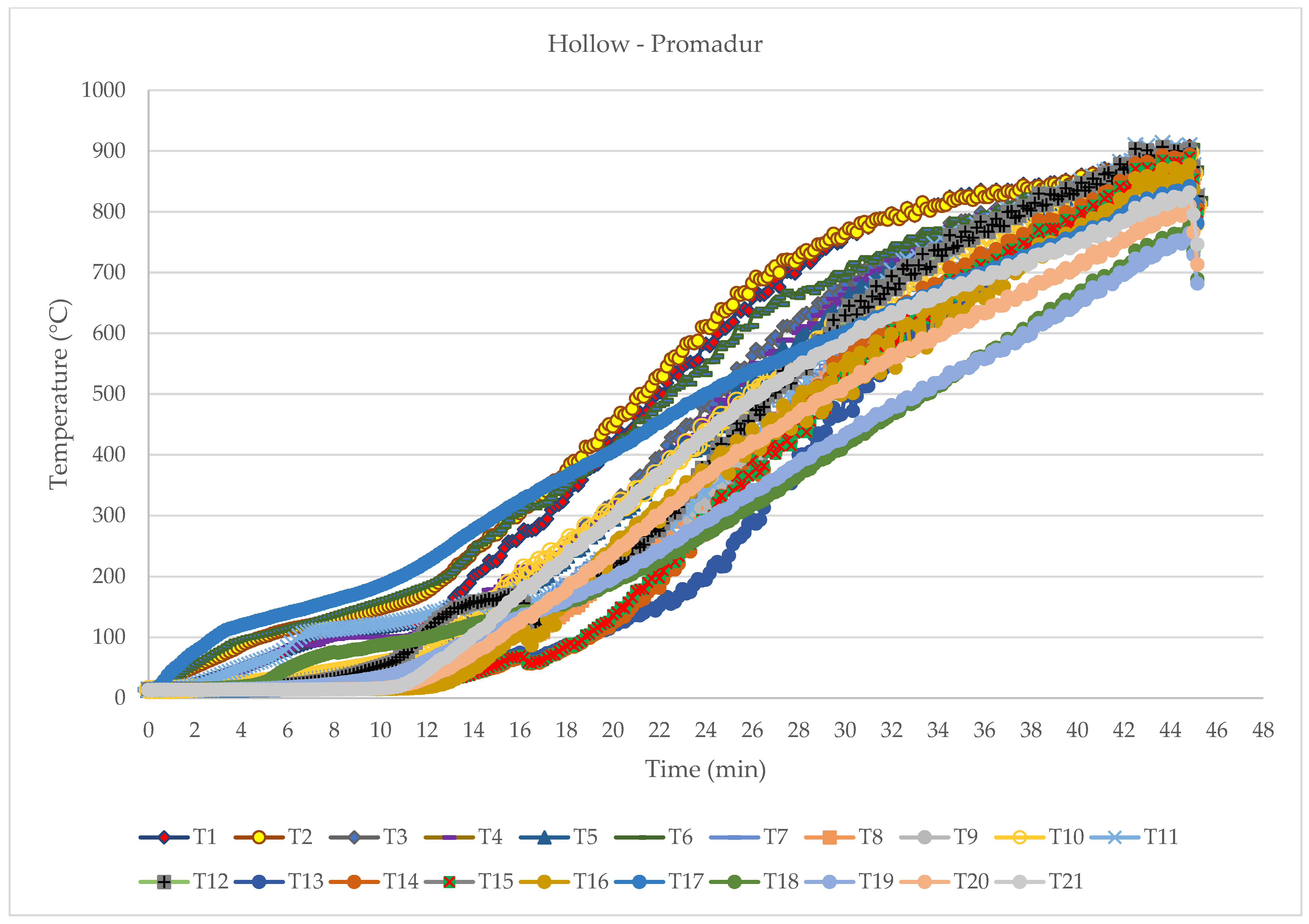
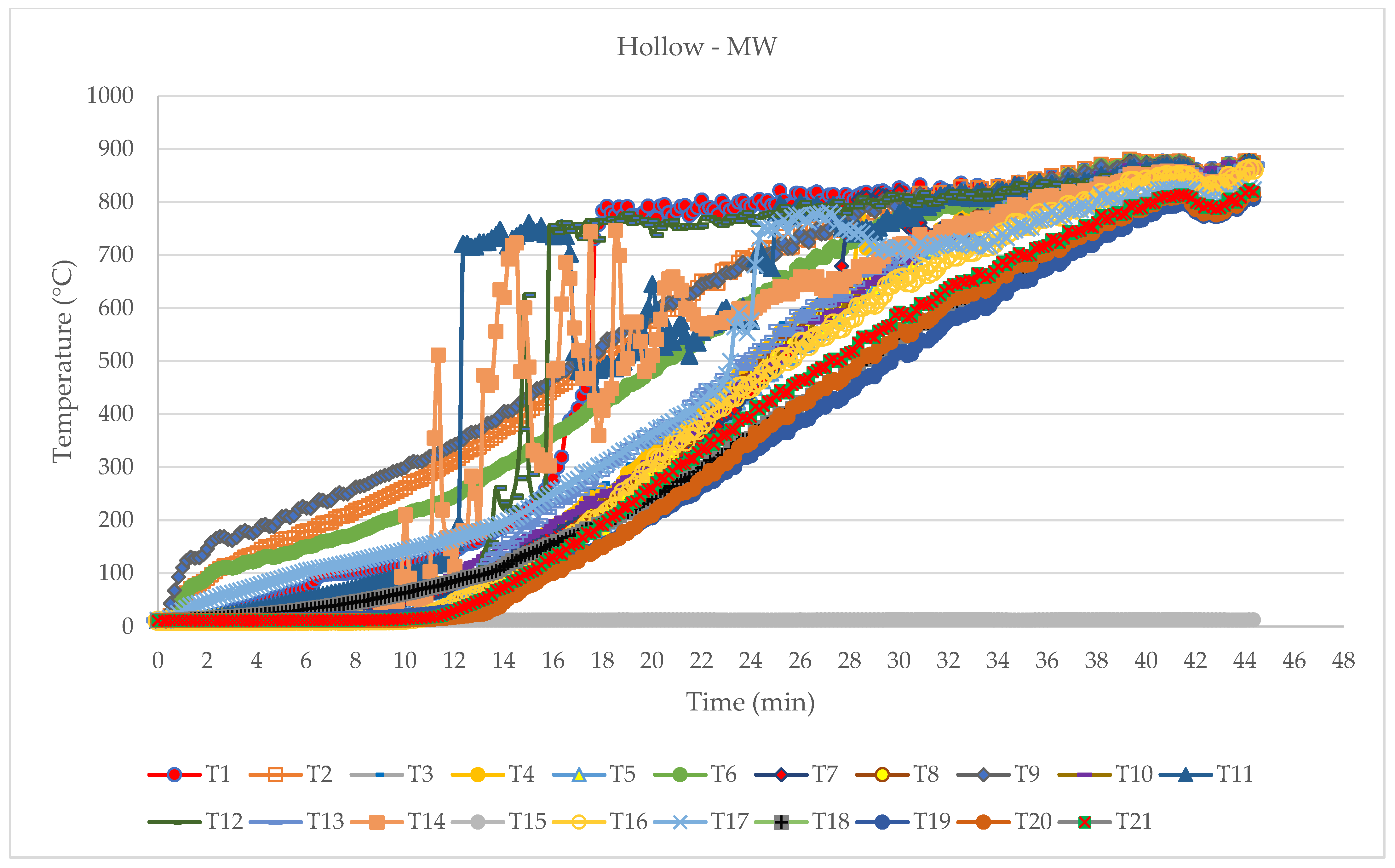
Temperatures through the sample cross-section were measured with 21 NiCr-Ni thermocouples, (type K) wire Ø 0.5 mm. The installation process of thermocouples can be seen in
Figure 11. After insertion, the thermocouples were additionally fixed with wooden wedges, while the holes were filled with fireproof silicone. In this way, the position and depth of the thermocouples were fully ensured.
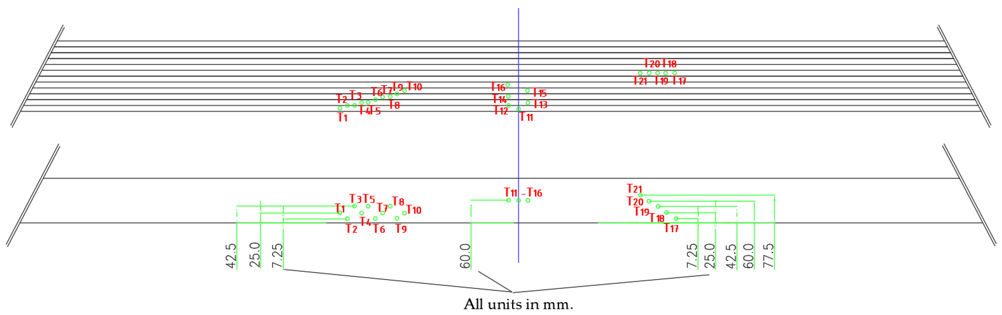
The thermocouple layout is shown in
Table 3 and
Figure 12, while thermocouple installation depth is shown it
Table 4.
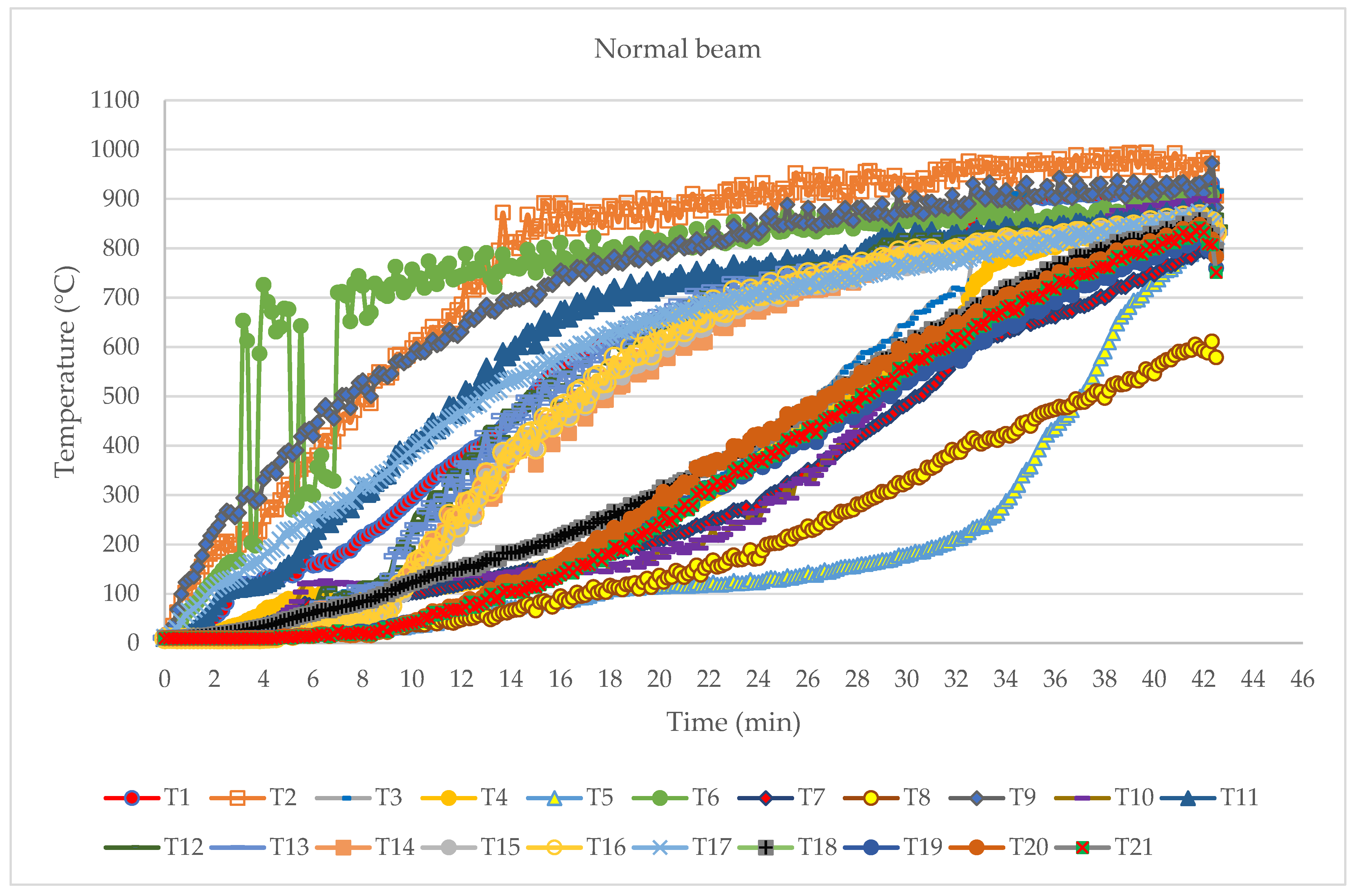
The layout of the thermoelements was chosen to cover temperature measurements from all exposed sides. The thermocouples were divided into three groups with seven thermocouples in each series depending on their placement in the beam. The group of thermoelements T11–T16 measured the development of temperature due to the influence of fire exposure from the bottom side, the group T17–T21 measured the temperatures assumed to mainly depend on the fire exposure from the side of the beam, while the group of thermoelements T1–T10 measured the notional charring rate and development of temperature.
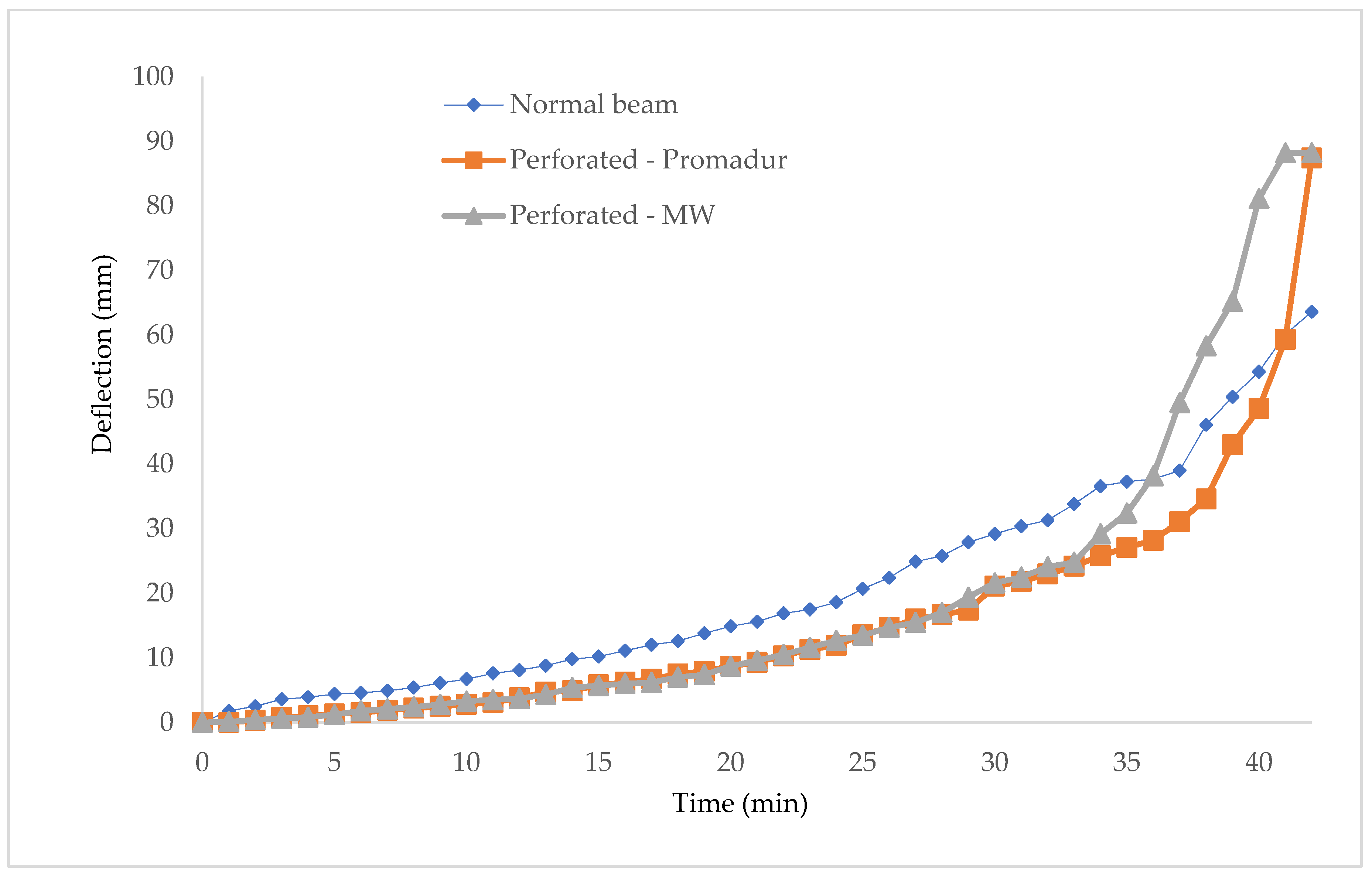
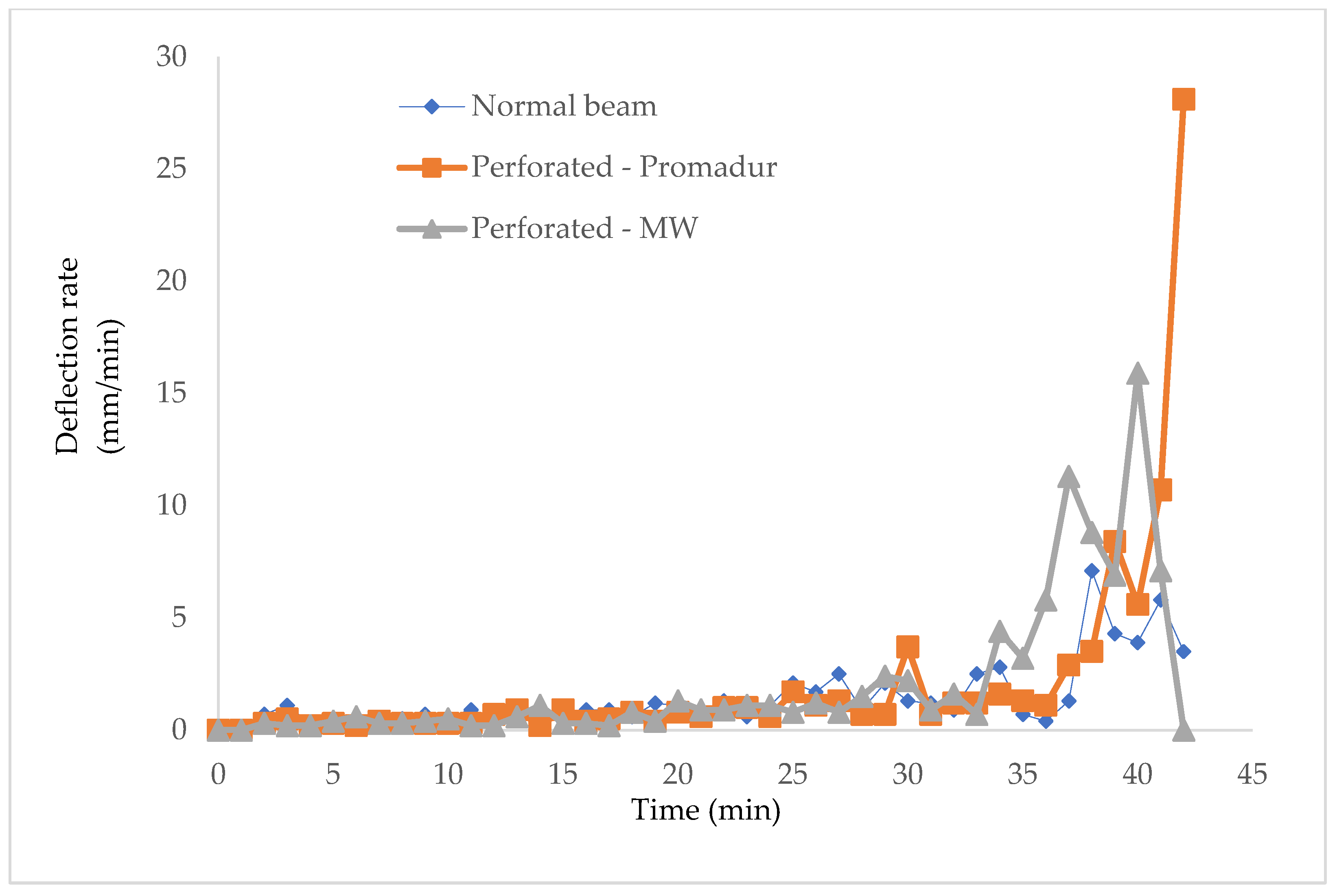
In addition to temperature development, the deflection D
1, in the middle of the beam was measured. To meet the sample load criteria, the deflection must be less than:
Furthermore, the deflection increment rate must be less than:
The failure according to the load-bearing criteria occurred when the following conditions were met:
or
and
The load conditions were applied in accordance with the standard HRN EN 1365-3: 2002, point 7.3 [
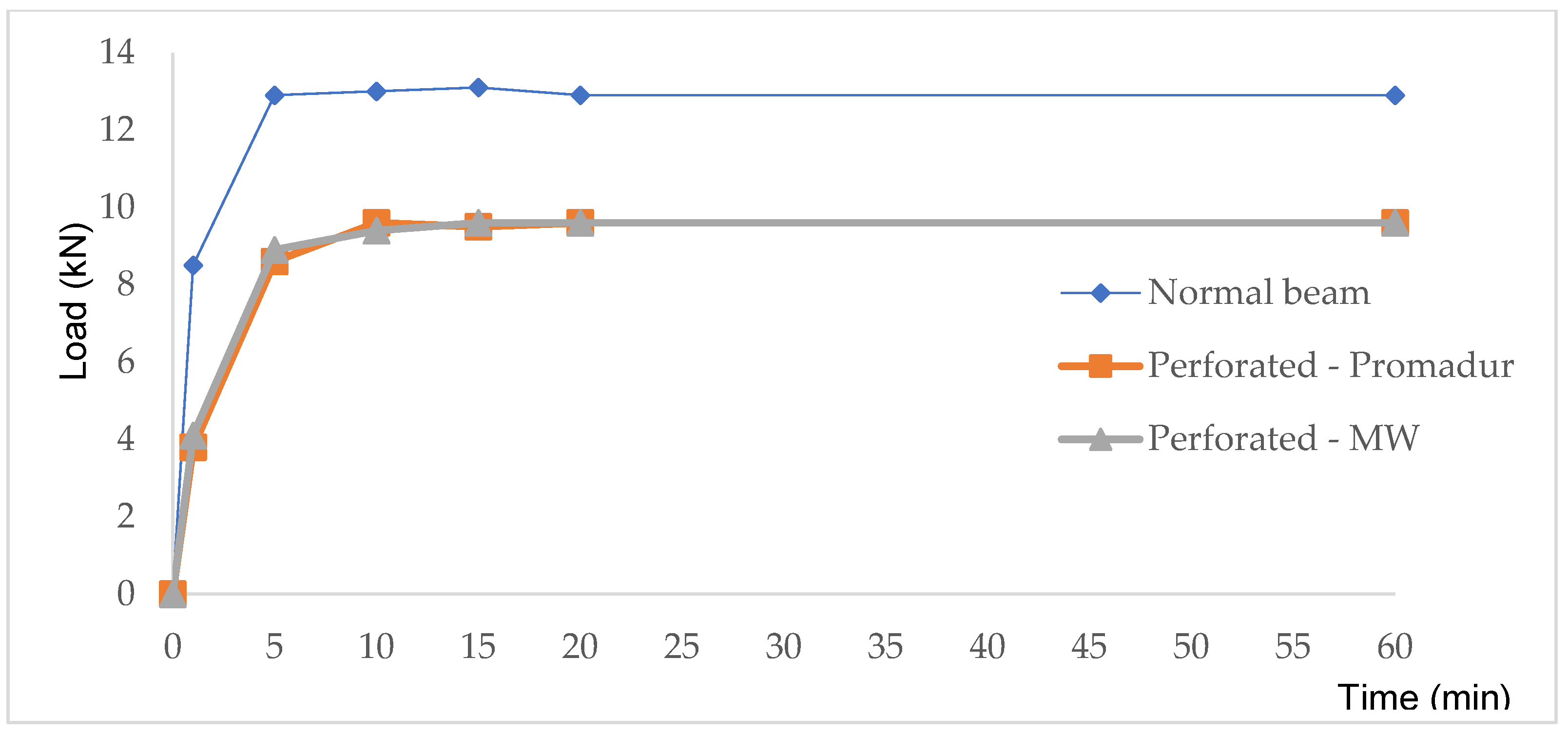
29]. The sample was loaded at two points, located on thirds of the length of the beam between the supports, with 6.5 kN, which corresponds to the total applied load on the sample in the amount of 13 kN for the normal beam, and 4.8 kN (in thirds), in total 9.6 kN for hollow beams.
The required load was achieved using a hydraulic system acting on the test specimen by means of two cylinders. Hydraulic cylinders with a maximum stroke of 100 mm were used, thus limiting the range of deflection of the sample at which the required load could be achieved.
The load was applied to the sample in the middle of the beam width at a distance of 1440 mm.
The sample was gradually loaded before the test. The required total load was reached 15 min before the start and was maintained throughout the test (see
Figure 13).


