
The Effect of Seawater on Mortar Matrix Coated with Hybrid Nano-Silica-Modified Surface Protection Materials


Abstract
:1. Introduction
2. Materials and Methods
2.1. Materials
2.2. Specimen Preparation
2.3. Test Methods
2.3.1. Rebound Surface Hardness
2.3.2. X-ray Diffraction (XRD)
2.3.3. Fourier Transform Infrared Spectroscopy (FTIR)
2.3.4. Mercury Intrusion Porosimetry Test (MIP)
2.3.5. Thermodynamic Modeling
3. Results and Discussion
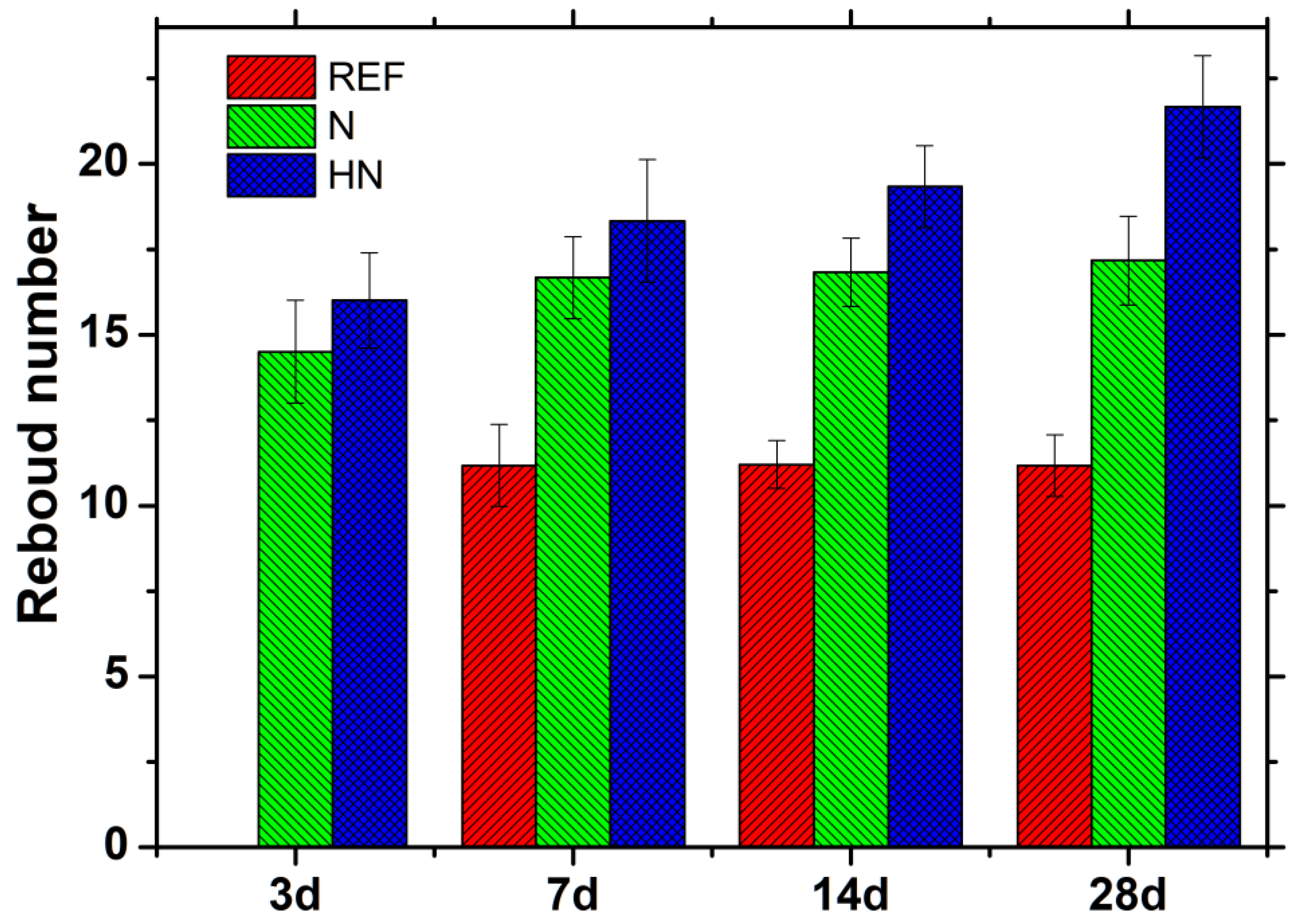
3.1. Surface Hardness Change
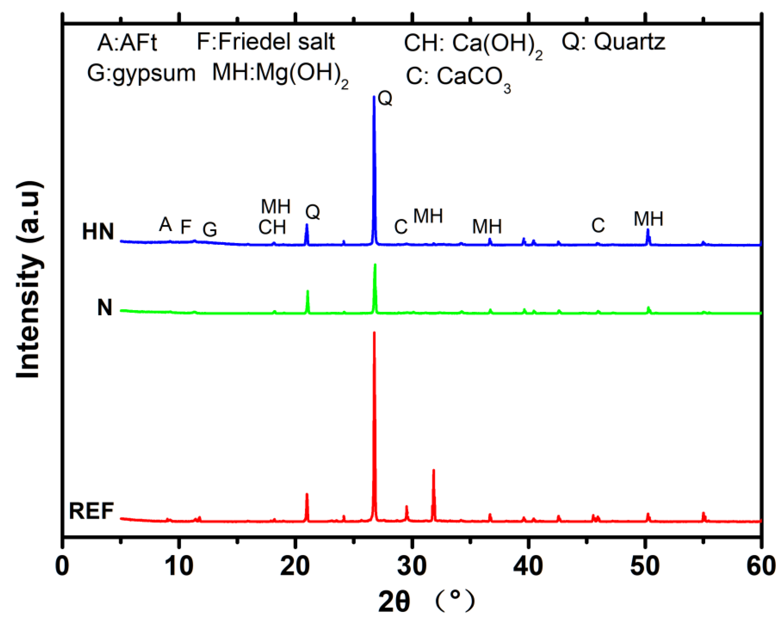
3.2. XRD Analysis
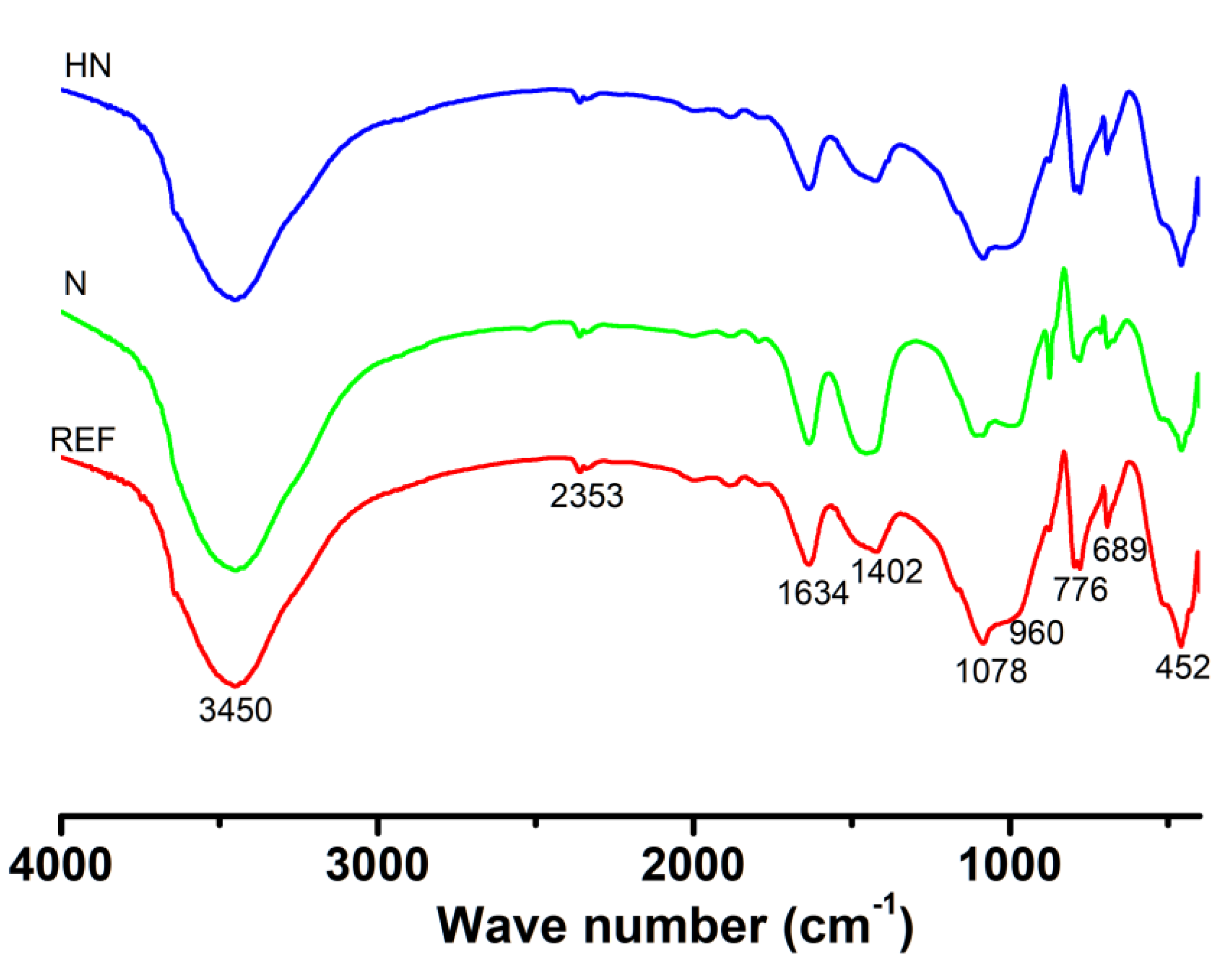
3.3. FTIR Analysis
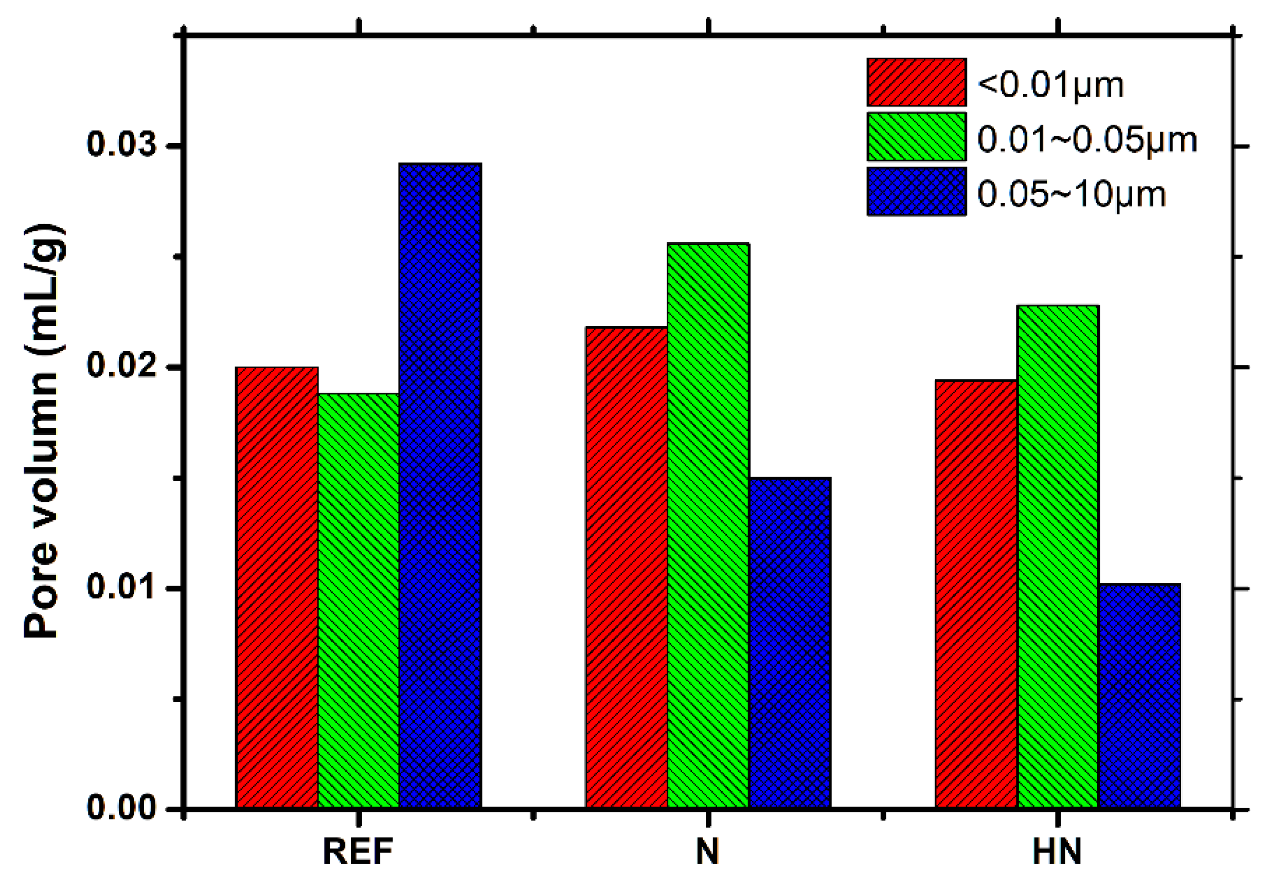
3.4. MIP Analysis
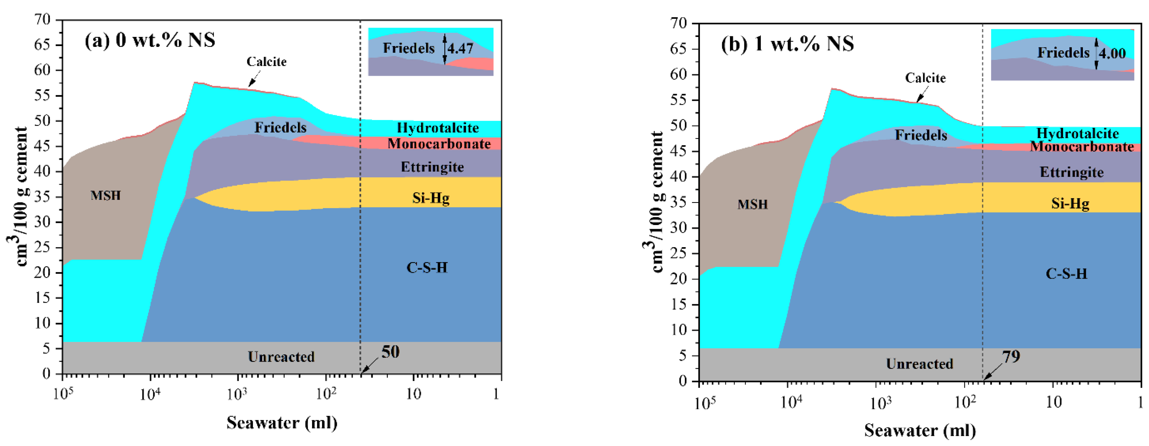
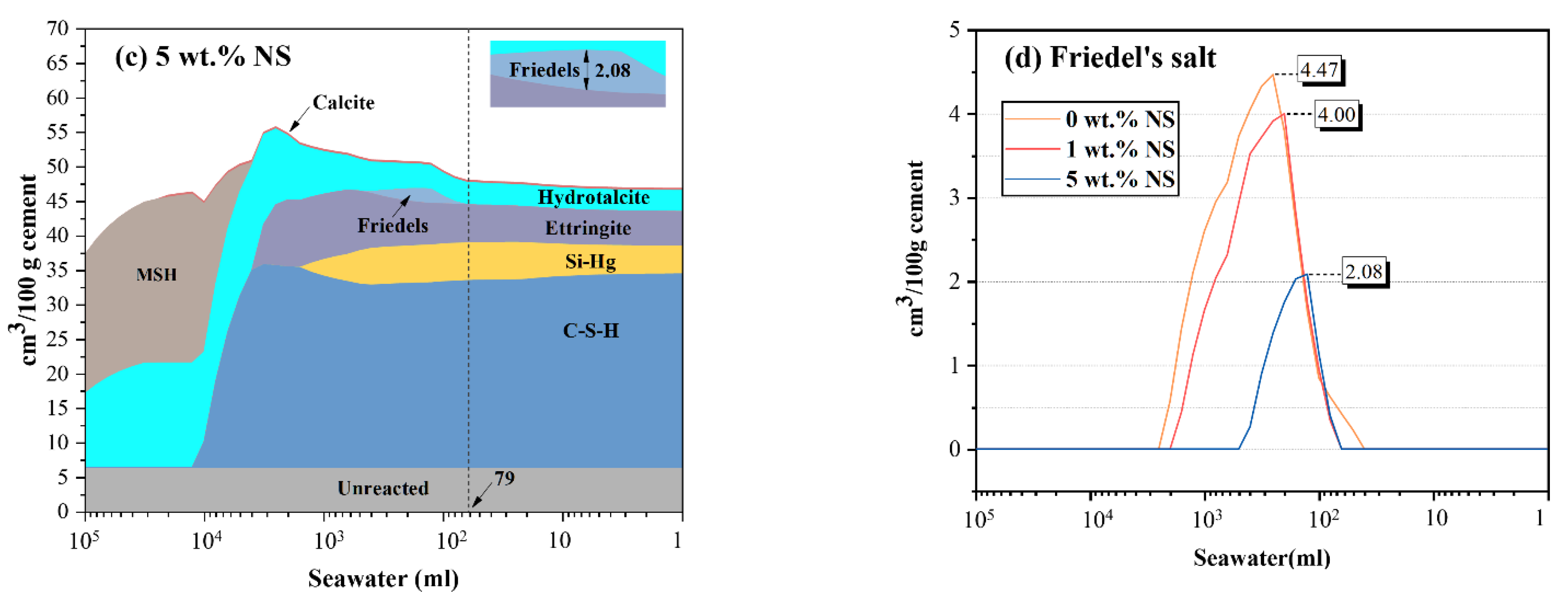
3.5. Thermodynamic Modeling
4. Conclusions
- The addition of hybrid nano-silica beneficially contributes to the improvement in surface hardness of surface protection materials exposed to seawater. After exposed to seawater for 28 d, the rebound number of SPM-HN increases by 94.0%, while and that of SPM-N increases by 57.3%, compared with REF;
- The incorporation of HN helps to inhibit the formation of ettringite, thaumasite, and maintains more C-S-H with a high Ca/Si ratio in the microstructure of SPM. However, it weakens the ability of chemically binding chloride of SPM;
- A lower total porosity and large capillary pore volume in SPM-HN are observed. This highlights the pore-refinement effect of hybrid nanomaterials;
- The results of thermodynamic modeling show that the incorporation of nano-silica could generate more C-S-H, delay the formation of Friedel’s salt, and decrease the maximum volume of Friedel’s salt when SPM are exposed to seawater.
Author Contributions
Funding
Institutional Review Board Statement
Informed Consent Statement
Data Availability Statement
Acknowledgments
Conflicts of Interest
References
- Monteiro, P.J.M.; Miller, S.; Horvath, A. Towards sustainable concrete. Nat. Mater. 2017, 16, 698–699. [Google Scholar] [CrossRef] [PubMed]
- Biernacki, J.J.; Bullard, J.W.; Sant, G.; Brown, K.; Glasser, F.P.; Jones, S.; Ley, T.; Livingston, R.; Nicoleau, L.; Olek, J.; et al. Cements in the 21(st) Century: Challenges, Perspectives, and Opportunities. J. Am. Ceram. Soc. 2017, 1007, 2746–2773. [Google Scholar] [CrossRef] [PubMed]
- Wei, Z.; Wang, B.; Falzone, G.; La Plante, E.C.; Okoronkwo, M.U.; She, Z.; Oey, T.; Balonis, M.; Neithalath, N.; Pilon, L.; et al. Clinkering-free cementation by fly ash carbonation. J. CO2 Util. 2018, 23, 117–127. [Google Scholar] [CrossRef]
- Chang, H.; Wang, X.; Wang, Y.; Li, S.; Wang, J.; Liu, J.; Feng, P. Influence of low vacuum condition on mechanical performance and microstructure of hardened cement paste at early age. Constr. Build. Mater. 2022, 346, 128358. [Google Scholar] [CrossRef]
- Ardalan, R.B.; Jamshidi, N.; Arabameri, H.; Joshaghani, A.; Mehrinejad, M.; Sharafi, P. Enhancing the permeability and abrasion resistance of concrete using colloidal nano-SiO2 oxide and spraying nanosilicon practices. Constr. Build. Mater. 2017, 146, 128–135. [Google Scholar] [CrossRef]
- Pan, X.; Shi, Z.; Shi, C.; Ling, T.-C.; Li, N. A review on surface treatment for concrete—Part 2: Performance. Constr. Build. Mater. 2017, 133, 81–90. [Google Scholar] [CrossRef]
- Xu, K.; Ren, S.; Song, J.; Liu, J.; Liu, Z.; Sun, J.; Ling, S. Colorful superhydrophobic concrete coating. Chem. Eng. J. 2021, 403, 126348. [Google Scholar] [CrossRef]
- Xia, K.; Gu, Y.; Jiang, L.; Guo, M.; Chen, L.; Hu, F. Carbonation Resistance of Surface Protective Materials Modified with Hybrid NanoSiO2. Coatings 2021, 113, 269. [Google Scholar] [CrossRef]
- Sánchez, M.; Alonso, M.; González, R. Preliminary attempt of hardened mortar sealing by colloidal nanosilica migration. Constr. Build. Mater. 2014, 66, 306–312. [Google Scholar] [CrossRef]
- Hou, P.; Cheng, X.; Qian, J.; Zhang, R.; Cao, W.; Shah, S.P. Characteristics of surface-treatment of nano-SiO2 on the transport properties of hardened cement pastes with different water-to-cement ratios. Cem. Concr. Compos. 2015, 55, 26–33. [Google Scholar] [CrossRef]
- Javid, A.A.S.; Ghoddousi, P.; Zareechian, M.; Korayem, A.H. Effects of Spraying Various Nanoparticles at Early Ages on Improving Surface Characteristics of Concrete Pavements. Int. J. Civ. Eng. 2019, 17, 1455–1468. [Google Scholar] [CrossRef]
- Pan, X.; Shi, Z.; Shi, C.; Ling, T.-C.; Li, N. A review on concrete surface treatment Part I: Types and mechanisms. Constr. Build. Mater. 2017, 132, 578–590. [Google Scholar] [CrossRef]
- Gu, Y.; Ran, Q.; She, W.; Shu, X.; Liu, J. Effects and mechanisms of surface-treatment of cementitious materials with nanoSiO2@PCE core-shell nanoparticles. Constr. Build. Mater. 2018, 166, 12–22. [Google Scholar] [CrossRef]
- Zhang, B.; Tan, H.; Shen, W.; Xu, G.; Ma, B.; Ji, X. Nano-silica and silica fume modified cement mortar used as Surface Protection Material to enhance the impermeability. Cem. Concr. Compos. 2018, 92, 7–17. [Google Scholar] [CrossRef]
- Wu, M.; Zhang, Y.; Ji, Y.; Liu, G.; Liu, C.; She, W.; Sun, W. Reducing environmental impacts and carbon emissions: Study of effects of superfine cement particles on blended cement containing high volume mineral admixtures. J. Clean. Prod. 2018, 196, 358–369. [Google Scholar] [CrossRef]
- Liu, X.; Ma, B.; Tan, H.; Zhang, T.; Mei, J.; Qi, H.; Chen, P.; Wang, J. Effects of colloidal nano-SiO2 on the immobilization of chloride ions in cement-fly ash system. Cem. Concr. Compos. 2020, 110, 103596. [Google Scholar] [CrossRef]
- Lyu, K.; Xu, J.; Gu, Y.; Xia, K.; Wang, L.; Liu, W.; Xie, X. Evaluation of the Surface Performance of Mortar Matrix Subjected to Sodium Chloride Solution Modified with Hybrid Nanosilica Cement Paste. Sustainability 2022, 1416, 9876. [Google Scholar] [CrossRef]
- Kulik, D.A.; Wagner, T.; Dmytrieva, S.V.; Kosakowski, G.; Hingerl, F.F.; Chudnenko, K.V.; Berner, U.R. GEM-Selektor geochemical modeling package: Revised algorithm and GEMS3K numerical kernel for coupled simulation codes. Comput. Geosci. 2012, 17, 1–14. [Google Scholar] [CrossRef]
- Lothenbach, B.; Kulik, D.A.; Matschei, T.; Balonis, M.; Baquerizo, L.; Dilnesa, B.; Miron, G.D.; Myers, R.J. Cemdata18: A chemical thermodynamic database for hydrated Portland cements and alkali-activated materials. Cem. Concr. Res. 2019, 115, 472–506. [Google Scholar] [CrossRef]
- Pan, X.; Shi, C.; Zhang, J.; Jia, L.; Chong, L. Effect of inorganic surface treatment on surface hardness and carbonation of cement-based materials. Cem. Concr. Compos. 2018, 90, 218–224. [Google Scholar] [CrossRef]
- Gu, Y.; Ran, Q.; She, W.; Liu, J. Modifying Cement Hydration with NS@ PCE Core-Shell Nanoparticles. Adv. Mater. Sci. Eng. 2017, 2017, 3823621. [Google Scholar] [CrossRef]
- De Weerdt, K.; Justnes, H. The effect of sea water on the phase assemblage of hydrated cement paste. Cem. Concr. Compos. 2015, 55, 215–222. [Google Scholar] [CrossRef]
- De Weerdt, K.; Justnes, H.; Geiker, M.R. Changes in the phase assemblage of concrete exposed to sea water. Cem. Concr. Compos. 2014, 47, 53–63. [Google Scholar] [CrossRef]
- Shaikh, F.U.A.; Supit, S.W.M. Chloride induced corrosion durability of high volume fly ash concretes containing nano particles. Constr. Build. Mater. 2015, 99, 208–225. [Google Scholar] [CrossRef]
- Zhang, M.; Islam, J. Use of nano-silica to reduce setting time and increase early strength of concretes with high volumes of fly ash or slag. Constr. Build. Mater. 2012, 29, 573–580. [Google Scholar] [CrossRef]
- Jennings, H.M.; Kumar, A.; Sant, G. Quantitative discrimination of the nano-pore-structure of cement paste during drying: New insights from water sorption isotherms. Cem. Concr. Res. 2015, 76, 27–36. [Google Scholar] [CrossRef]
- Kong, X.; Shi, Z.; Lu, Z. Synthesis of novel polymer nano-particles and their interaction with cement. Constr. Build. Mater. 2014, 68, 434–443. [Google Scholar] [CrossRef]


| CaO | SiO2 | Al2O3 | MgO | Fe2O3 | SO3 | K2O | Na2O | |
|---|---|---|---|---|---|---|---|---|
| Cement | 62.83 | 20.5 | 5.61 | 1.70 | 3.84 | 3.07 | 1.31 | 0.21 |
| Fly ash | 3.39 | 57.53 | 28.34 | 1.22 | 4.07 | 0.74 | 2.51 | 1.06 |
| Slag | 26.51 | 46.29 | 7.48 | 10.46 | 5.05 | 0.25 | 1.76 | 0.09 |
| NaCl | NaSO4 | MgCl2·6H2O | CaCl2 | KCl2 |
|---|---|---|---|---|
| 24.5 | 4.1 | 11.1 | 1.2 | 0.7 |
| Blends | Volumes of Hydrates (cm3/100 g Cement) | |||||
|---|---|---|---|---|---|---|
| Calcite | Hydrotalcite | Monocarbonate | Ettringite | Si–Hg | C-S-H | |
| 0 wt.% NS | 0.00 | 3.24 | 2.40 | 5.44 | 5.94 | 26.58 |
| 1 wt.% NS | 0.00 | 3.20 | 1.62 | 5.97 | 5.85 | 26.66 |
| 5 wt.% NS | 0.32 | 3.04 | 0.00 | 5.02 | 4.04 | 28.08 |
Publisher’s Note: MDPI stays neutral with regard to jurisdictional claims in published maps and institutional affiliations. |
© 2022 by the authors. Licensee MDPI, Basel, Switzerland. This article is an open access article distributed under the terms and conditions of the Creative Commons Attribution (CC BY) license (https://creativecommons.org/licenses/by/4.0/).
Share and Cite
Gu, Y.; Fan, R.; Xia, K.; Lyu, K.; Wei, Z.; Guo, M. The Effect of Seawater on Mortar Matrix Coated with Hybrid Nano-Silica-Modified Surface Protection Materials. Polymers 2022, 14, 4080. https://doi.org/10.3390/polym14194080
Gu Y, Fan R, Xia K, Lyu K, Wei Z, Guo M. The Effect of Seawater on Mortar Matrix Coated with Hybrid Nano-Silica-Modified Surface Protection Materials. Polymers. 2022; 14(19):4080. https://doi.org/10.3390/polym14194080
Chicago/Turabian StyleGu, Yue, Ruyan Fan, Kailun Xia, Kai Lyu, Zhenhua Wei, and Mingzhi Guo. 2022. "The Effect of Seawater on Mortar Matrix Coated with Hybrid Nano-Silica-Modified Surface Protection Materials" Polymers 14, no. 19: 4080. https://doi.org/10.3390/polym14194080
APA StyleGu, Y., Fan, R., Xia, K., Lyu, K., Wei, Z., & Guo, M. (2022). The Effect of Seawater on Mortar Matrix Coated with Hybrid Nano-Silica-Modified Surface Protection Materials. Polymers, 14(19), 4080. https://doi.org/10.3390/polym14194080