
Morphology Analysis of Friction Surfaces of Composites Based on PTFE and Layered Silicates
 ,
,
Abstract
:1. Introduction
2. Materials and Methods
2.1. Materials
2.2. Sample Preparation
2.3. Experimental Methods
3. Results and Discussion
3.1. Tribological Tests
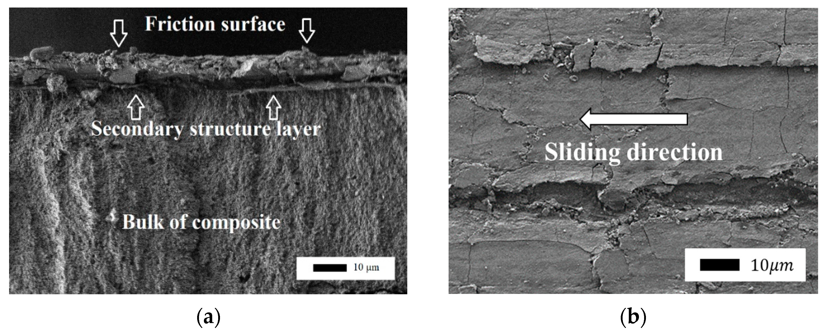
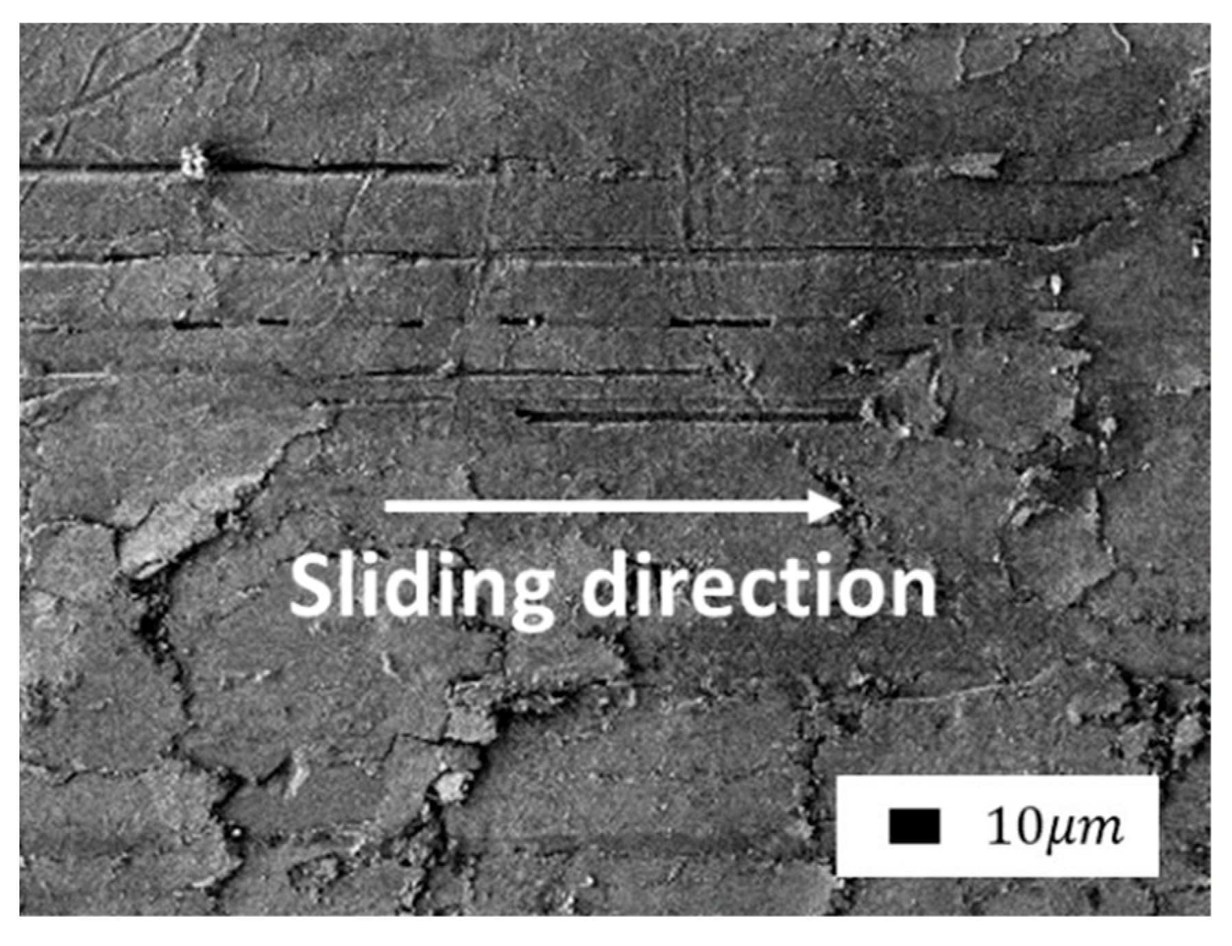
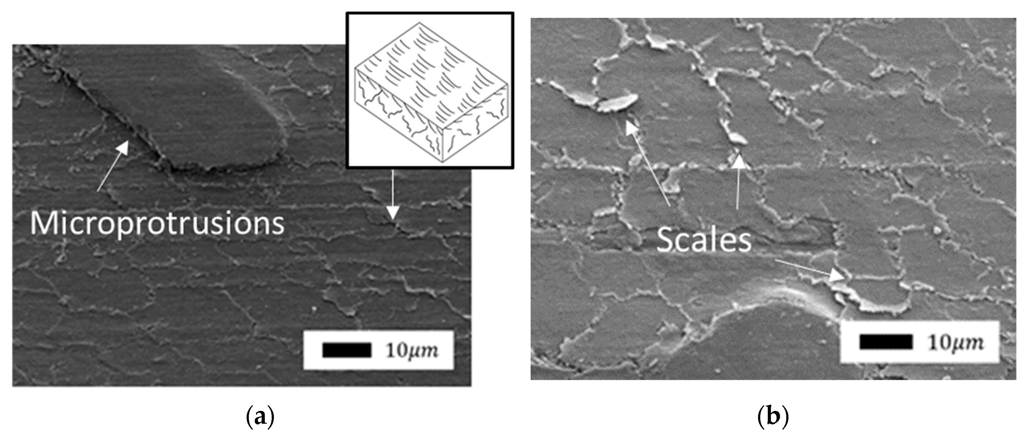
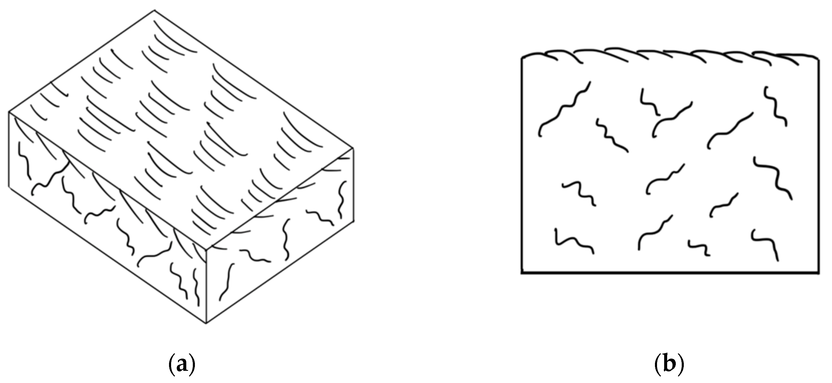
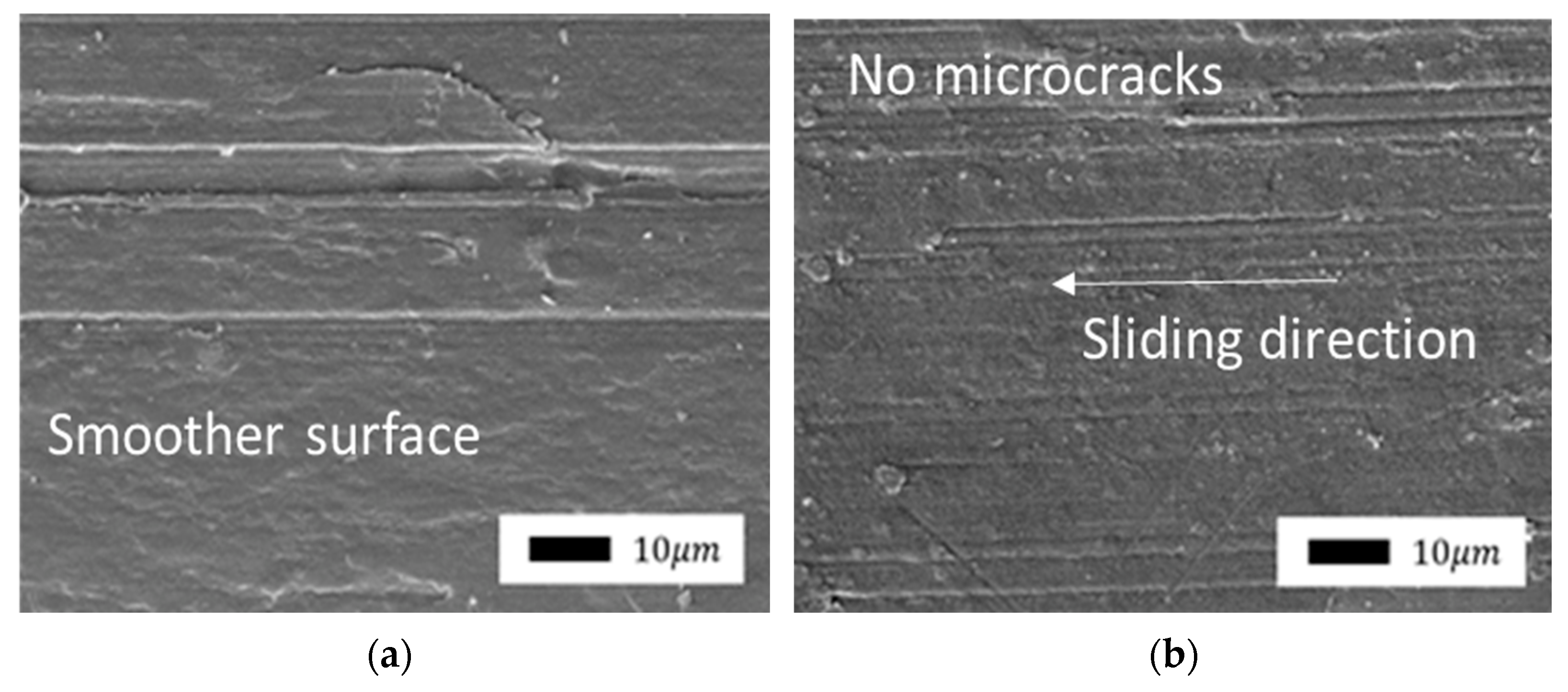
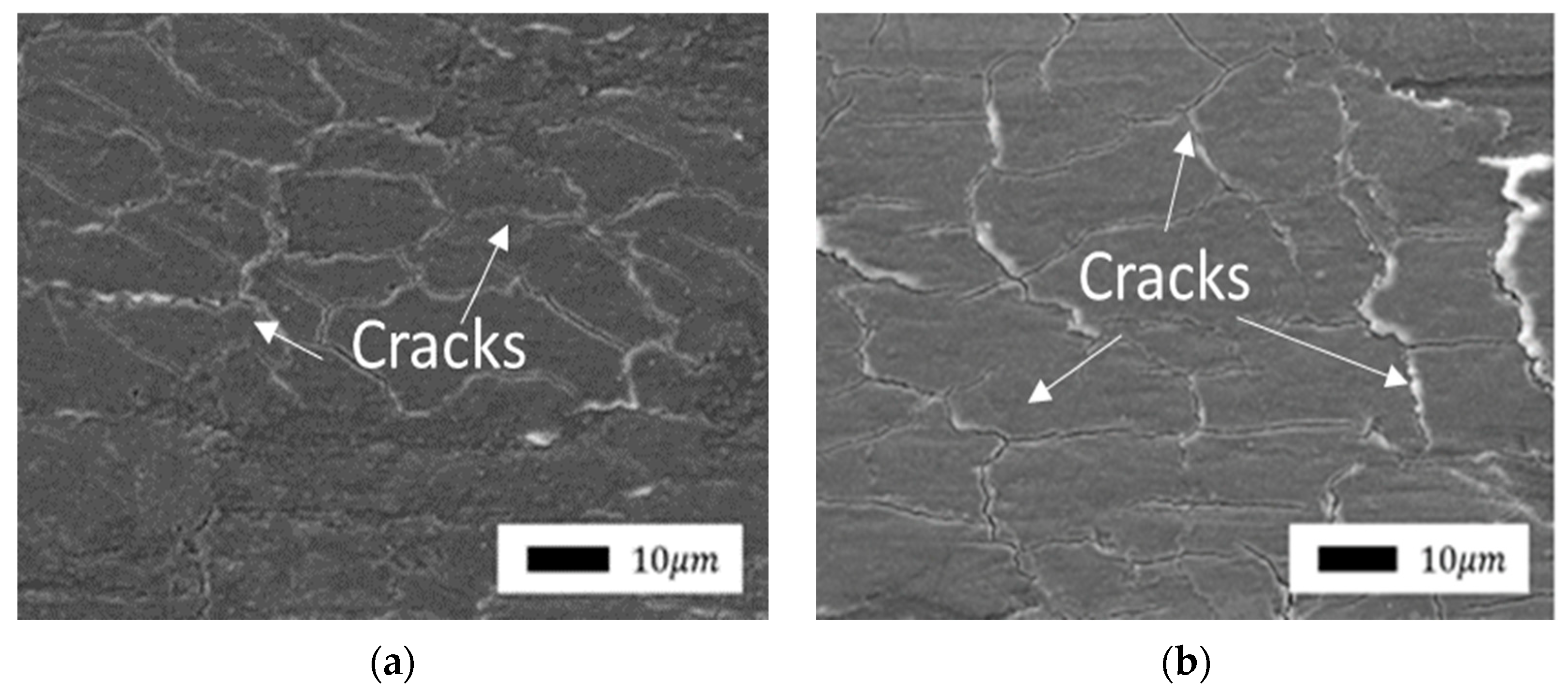
3.2. Morphology Analysis
4. Conclusions
Author Contributions
Funding
Institutional Review Board Statement
Informed Consent Statement
Data Availability Statement
Conflicts of Interest
References
- Nak-Ho, S.; Suh, N.P. Effect of fiber orientation on friction and wear of fiber reinforced polymeric composites. Wear 1979, 53, 129–141. [Google Scholar] [CrossRef]
- Sonawane, A.; Deshpande, A.; Chinchanikar, S.; Munde, Y. Dry sliding wear characteristics of carbon filled polytetrafluoroethylene (PTFE) composite against Aluminium 6061 alloy. Mater. Today Proc. 2021, 44, 3888–3893. [Google Scholar] [CrossRef]
- Lin, Z.; Gao, B.; Li, X.; Yu, K. Effect of abrasive grain size on surface particle deposition behaviour of PTFE/bronze composites during abrasive wear. Tribol. Int. 2019, 139, 12–21. [Google Scholar] [CrossRef]
- Burris, D.L.; Sawyer, W.G. Improved wear resistance in alumina-PTFE nanocomposites with irregular shaped nanoparticles. Wear 2006, 260, 915–918. [Google Scholar] [CrossRef]
- Li, F.; Yan, F.-Y.; Yu, L.-G.; Liu, W.-M. The tribological behaviors of copper-coated graphite filled PTFE composites. Wear 2000, 237, 33–38. [Google Scholar] [CrossRef]
- Chen, W.X.; Li, F.; Han, G.; Xia, J.B.; Wang, L.Y.; Tu, J.P.; Xu, Z.D. Tribological Behavior of Carbon-Nanotube-Filled PTFE Composites. Tribol. Lett. 2003, 15, 275–278. [Google Scholar] [CrossRef]
- Aderikha, V.; Krasnov, A.; Shapovalov, V.; Golub, A. Peculiarities of tribological behavior of low-filled composites based on polytetrafluoroethylene (PTFE) and molybdenum disulfide. Wear 2014, 320, 135–142. [Google Scholar] [CrossRef]
- Makinson, K.R.; Tabor, D. The friction and transfer of polytetrafluoroethylene. Proc. R. Soc. Lond. Ser. A Math. Phys. Sci. 1964, 281, 49–61. [Google Scholar] [CrossRef]
- Ye, J.; Khare, H.; Burris, D. Transfer film evolution and its role in promoting ultra-low wear of a PTFE nanocomposite. Wear 2013, 297, 1095–1102. [Google Scholar] [CrossRef]
- Sawyer, W.G.; Argibay, N.; Burris, D.L.; Krick, B.A. Mechanistic Studies in Friction and Wear of Bulk Materials. Annu. Rev. Mater. Sci. 2014, 44, 395–427. [Google Scholar] [CrossRef]
- Fusaro, R. Self-lubricating polymer composites and polymer transfer film lubrication for space applications. Tribol. Int. 1990, 23, 105–122. [Google Scholar] [CrossRef] [Green Version]
- Bowden, F.P.; Tabor, D. The Friction and Lubrication of Solids; Oxford classic texts in the physical sciences; Clarendon Press: Oxford, UK; Oxford University Press: New York, NY, USA, 2001. [Google Scholar]
- Tabor, D. Friction, Adhesion and Boundary Lubrication of Polymers. In Advances in Polymer Friction and Wear; Lee, L.-H., Ed.; Springer: Boston, MA, USA, 1974; pp. 5–30. [Google Scholar]
- Bely, V.; Savkin, V.; Sviridyonok, A. Effect of structure on polymer friction. Wear 1971, 18, 11–18. [Google Scholar] [CrossRef]
- Bahadur, S.; Tabor, D. The wear of filled polytetrafluoroethylene. Wear 1984, 98, 1–13. [Google Scholar] [CrossRef]
- Korshak, V.V.; Gribova, I.A.; Krasnov, A.P.; Aderikha, V.N. Tribochemical Processes and Wear Resistance of Polymeric Materials. ASLE Trans. 1983, 26, 401–404. [Google Scholar] [CrossRef]
- Sleptsova, S.A.; Okhlopkova, A.A.; Kapitonova, I.V.; Lazareva, N.N.; Makarov, M.M.; Nikiforov, L. Spectroscopic study of tribooxidation processes in modified PTFE. J. Frict. Wear 2016, 37, 129–135. [Google Scholar] [CrossRef]
- Vasilev, A.P.; Struchkova, T.S.; Nikiforov, L.A.; Okhlopkova, A.A.; Grakovich, P.N.; Le Shim, E.; Cho, J.-H. Mechanical and Tribological Properties of Polytetrafluoroethylene Composites with Carbon Fiber and Layered Silicate Fillers. Molecules 2019, 24, 224. [Google Scholar] [CrossRef] [Green Version]
- Sleptsova, S.A.; Lazareva, N.N.; Fedoseeva, V.I.; Kapitonova, Y.V.; Okhlopkova, A.A. The Influence of Metal Cations of Mechanoactivated Bentonite on Tribochemical Processes in PTFE. J. Frict. Wear 2018, 39, 469–475. [Google Scholar] [CrossRef]
- Wang, Q.J.; Cheng, H.S. Average Reynolds Equation. In Encyclopedia of Tribology; Wang, Q.J., Chung, Y.-W., Eds.; Springer: Boston, MA, USA, 2013; pp. 154–159. ISBN 978-0-387-92896-8. [Google Scholar]
- Ghanbarzadeh, A.; Piras, E.; Wilson, M.C.T.; Morina, A.; Neville, A. Numerical Study of the Effect of Tribofilm Kinetics and Its Hardness on the Roughness Evolution of the Substrate in Boundary Lubrication Regime. Tribol. Trans. 2019, 62, 747–759. [Google Scholar] [CrossRef]
- Sleptsova, S.A.; Kapitonova, Y.V.; Lazareva, N.N.; Okhlopkova, A.A.; Grigoryeva, L.A. Effect of ultrasonic vibrations on the properties of PTFE/layered silicate + magnesium spinel. AIP Conf. Proc. 2018, 2051, 020288. [Google Scholar] [CrossRef]
- Sleptsova, S.; Lazareva, N.; Kapitonova, Y. Effect of Mechanically Activated Layered Silicate on the Properties and Structure of Polytetrafluoroethylene. Mater. Sci. Forum 2019, 945, 384–388. [Google Scholar] [CrossRef]
- Alexandre, M.; Dubois, P. Polymer-layered silicate nanocomposites: Preparation, properties and uses of a new class of materials. Mater. Sci. Eng. R Rep. 2000, 28, 1–63. [Google Scholar] [CrossRef]
- Mittal, V. Polymer Layered Silicate Nanocomposites: A Review. Materials 2009, 2, 992. [Google Scholar] [CrossRef] [Green Version]
- Pavlidou, S.; Papaspyrides, C.D. A review on polymer–layered silicate nanocomposites. Prog. Polym. Sci. 2008, 33, 1119–1198. [Google Scholar] [CrossRef]
- Ray, S.S.; Okamoto, M. Polymer/layered silicate nanocomposites: A review from preparation to processing. Prog. Polym. Sci. 2003, 28, 1539–1641. [Google Scholar] [CrossRef]
- Brindley, G.W.; Brown, G. Crystal Structures of Clay Minerals and Their X-Ray Identification; Brindley, G.W., Brown, G., Eds.; Mineralogical Society of Great Britain and Ireland: London, UK, 1980; Monograph No. 5; 495p. [Google Scholar]
- Ke, Y.C.; Stroeve, P. Polymer-Layered Silicate and Silica Nanocomposites, 1st ed.; Elsevier: Amsterdam, The Netherlands; Boston, MA, USA, 2005; 398p. [Google Scholar]
- Tillmanns, E. Minerals. In Their Constitution and Origin, 2nd ed.; Wenk, H.-R., Bulakh, A., Eds.; Cambridge University Press: Cambridge, UK, 2016; 672p. [Google Scholar]
- Friedrich, K.; Schlarb, A.K. Tribology of Polymeric Nanocomposites: Friction and Wear of Bulk Materials and Coatings, 1st ed.; Tribology and interface engineering series; Elsevier: Oxford, UK; New York, NY, USA, 2008. [Google Scholar]
- Okhlopkova, A.A.; Sleptsova, S.A.; Nikiforova, P.G.; Struchkova, T.S.; Ivanova, Z.S. Main Directions for Research on the Development of Tribotechnical Composites Used in the Arctic Regions (Experience of North-Eastern Federal University in Yakutsk). Inorg. Mater. Appl. Res. 2019, 10, 1441–1447. [Google Scholar] [CrossRef]
- Okhlopkova, A.A.; Petrova, P.N.; Popov, S.N.; Sleptsova, S. Polytetrafluoroethylene-based polymeric composite materials intended for triboengineering applications. Russ. J. Gen. Chem. 2009, 79, 686–692. [Google Scholar] [CrossRef]
- Taylor, R.I. Rough Surface Contact Modelling—A Review. Lubricants 2022, 10, 98. [Google Scholar] [CrossRef]
- Baki, V.A.; Ke, X.; Heath, A.; Calabria-Holley, J.; Terzi, C.; Sirin, M. The impact of mechanochemical activation on the physicochemical properties and pozzolanic reactivity of kaolinite, muscovite and montmorillonite. Cem. Concr. Res. 2022, 162, 106962. [Google Scholar] [CrossRef]
- Huang, P.; Li, Z.; Chen, M.; Hu, H.; Lei, Z.; Zhang, Q.; Yuan, W. Mechanochemical activation of serpentine for recovering Cu (II) from wastewater. Appl. Clay Sci. 2017, 149, 1–7. [Google Scholar] [CrossRef]
- Bekri-Abbes, I.; Srasra, E. Effect of mechanochemical treatment on structure and electrical properties of montmorillonite. J. Alloys Compd. 2016, 671, 34–42. [Google Scholar] [CrossRef]
- Baláž, P. Applied Mechanochemistry. In Mechanochemistry in Nanoscience and Minerals Engineering; Springer: Berlin/Heidelberg, Germany, 2008; pp. 297–405. [Google Scholar]
- Hrachová, J.; Komadel, P.; Fajnor, V. The effect of mechanical treatment on the structure of montmorillonite. Mater. Lett. 2007, 61, 3361–3365. [Google Scholar] [CrossRef]
- Mashkov, Y.K.; Ovchar, Z.N.; Surikov, V.I. The modification of structure and properties of composite materials based on polytetrafluoroethylene. In Structural Modification; Mechanical Engineering: Moscow, Russia, 2005; pp. 149–177. [Google Scholar]
- Myshkin, N.K.; Petrokovets, M.I.; Kovalev, A.V. Tribology of polymers: Adhesion, friction, wear, and mass-transfer. Tribol. Int. 2005, 38, 910–921. [Google Scholar] [CrossRef]
- Okhlopkova, A.A.; Sleptsova, S.A. Influence of Nanoceramics on the Properties of Polytetrafluoroethylene. Polym. Mech. 2003, 39, 123–128. [Google Scholar] [CrossRef]
- Harris, K.L.; Pitenis, A.A.; Sawyer, W.G.; Krick, B.A.; Blackman, G.S.; Kasprzak, D.J.; Junk, C.P. PTFE Tribology and the Role of Mechanochemistry in the Development of Protective Surface Films. Macromolecules 2015, 48, 3739–3745. [Google Scholar] [CrossRef]
- Tanaka, K.; Uchiyama, Y.; Toyooka, S. The mechanism of wear of polytetrafluoroethylene. Wear 1973, 23, 153–172. [Google Scholar] [CrossRef]
- Blanchet, T.A.; Kennedy, F.E. Sliding wear mechanism of polytetrafluoroethylene (PTFE) and PTFE composites. Wear 1992, 153, 229–243. [Google Scholar] [CrossRef]
- Biswas, S.; Vijayan, K. Friction and wear of PTFE—A review. Wear 1992, 158, 193–211. [Google Scholar] [CrossRef]
- Kostetsky, B.I. Friction, Lubrication and Wear in Machines; Technique: Kiev, Ukraine, 1970; pp. 22–61. [Google Scholar]
- Burris, D.L.; Boesl, B.; Bourne, G.R.; Sawyer, W.G. Polymeric Nanocomposites for Tribological Applications. Macromol. Mater. Eng. 2007, 292, 387–402. [Google Scholar] [CrossRef]


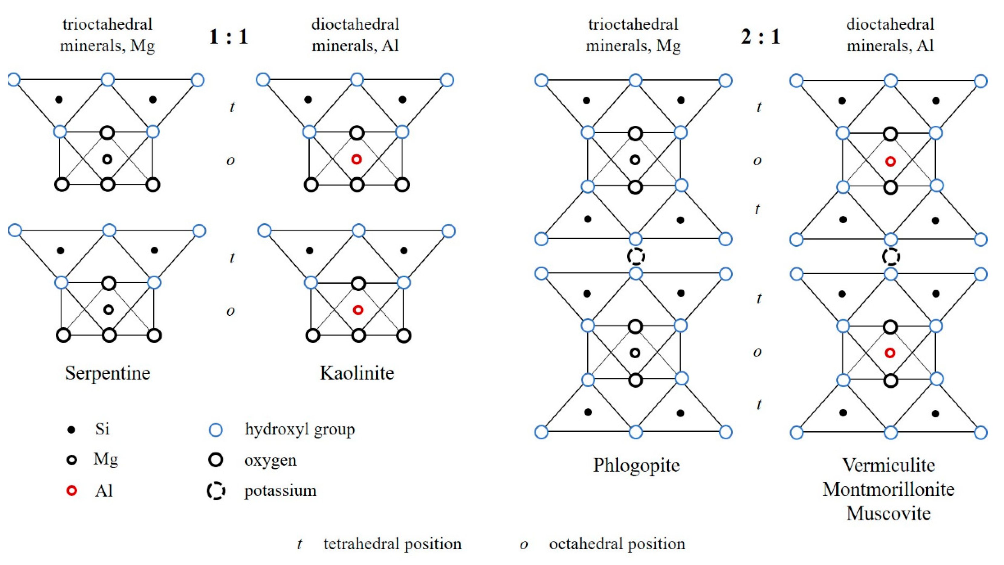
| Mineral | Classification | Deposit | Structural Formula | Laying Type | Cations in Tetrahedra | Octahedron Cations | Interlayer Cations |
|---|---|---|---|---|---|---|---|
| Kaolinite | polymineral, aluminum hydrosilicate | Glukhovetskoye Ukraine | Al2[Si2O5](OH)4 | 1:1 | Si4+ | Al3+ | - |
| Serpentine | mineral, magnesium hydrosilicate | Rikolatva Murmansk region, Russia | Mg3[Si2O5](OH)4 | 1:1 | Si4+ | Mg2+ | - |
| Vermiculite | mineral, aluminum, magnesium and iron hydroaluminosilicate (hydromica) | Inaglinskoye Yakutia, Russia | K2(Al,Mg,Fe)6[A12Si6O20](OH)4 | 2:1 | Si4+, Al3+ | Al3+, Mg2+, Fe2+ | M2+, 1·nH2O |
| Phlogopite | mineral, magnesium aluminum silicate (mica) | Emelgakskoye Yakutia, Russia | KMg3 [AlSi3O10](F,OH)2 | 2:1 | Si4+, Al3+ | Mg2+ | K+ |
| Muscovite | mineral, aluminum aluminosilicate (mica) | Rikolatva, Murmansk region | KAl2 [AlSi3O10](OH)2 | 2:1 | Si4+, Al3+ | Al3+ | K+ |
| Bentonite (montmorillonite) | polymineral hydroaluminosilicate contains ~ 70% montmorillonite | Dashukovskoye Ukraine | (Na,Ca)<0,4(Al,Mg,Fe)2–3 [(Si,Al)4O10](OH)2*nH2O | 2:1 | Si4+, Al3 | Al3+, Fe3+, Mg2+, Fe2+ | Complexn+, 2 |
| Serpentine, wt.% | MS, wt.% | Irun-in 1, mg/h | Ist. 2, mg/h | f 3 |
|---|---|---|---|---|
| 0 | 0 | 112.5 ± 3.4 | 65.5 ± 2.0 | 0.23 ± 0.007 |
| 2.0 | 0 | 1.8 ± 0.05 | 0.1 ± 0.003 | 0.32 ± 0.009 |
| 1.5 | 0.5 | 0.8 ± 0.02 | 0.2 ± 0.005 | 0.25 ± 0.007 |
| 1.8 | 0.2 | 0.9 ± 0.02 | 0.1 ± 0.003 | 0.24 ± 0.007 |
| 5.0 | 0 | 0.6 ± 0.01 | 0.1 ± 0.003 | 0.32 ± 0.009 |
| 4.0 | 1.0 | 0.4 ± 0.01 | 0.1 ± 0.003 | 0.26 ± 0.008 |
| 4.5 | 0.5 | 0.9 ± 0.02 | 0.1 ± 0.003 | 0.26 ± 0.008 |
| 4.8 | 0.2 | 1.0 ± 0.03 | 0.1 ± 0.003 | 0.27 ± 0.008 |
| Kaolinite, wt.% | MS, wt.% | Irun-in 1, mg/h | Ist. 2, mg/h | f 3 |
|---|---|---|---|---|
| 0 | 0 | 112.5 ± 3.4 | 65.5 ± 2.0 | 0.23 ± 0.007 |
| 2.0 | 0 | 1.9 ± 0.06 | 0.2 ± 0.005 | 0.33 ± 0.009 |
| 1.5 | 0.5 | 1.0 ± 0.03 | 0.1 ± 0.003 | 0.24 ± 0.007 |
| 1.8 | 0.2 | 1.1 ± 0.03 | 0.2 ± 0.005 | 0.22 ± 0.006 |
| 5.0 | 0 | 0.8 ± 0.02 | 0.1 ± 0.003 | 0.32 ± 0.009 |
| 4.0 | 1.0 | 1.6 ± 0.04 | 0.2 ± 0.005 | 0.27 ± 0.008 |
| 4.5 | 0.5 | 0.1 ± 0.01 | 0.1 ± 0.003 | 0.27 ± 0.008 |
| 4.8 | 0.2 | 0.5 ± 0.01 | 0.1 ± 0.003 | 0.23 ± 0.007 |
| Sample | Layered Silicates Content, wt.% | Irun-in 1, mg/h | Ist. 2, mg/h |
|---|---|---|---|
| PTFE | 0 | 112.5 ± 3.4 | 65.5 ± 2.0 |
| PTFE + Bentonite | 1 | 2.39 ± 0.07 | 2.50 ± 0.07 |
| 2 | 1.03 ± 0.03 | 0.59 ± 0.02 | |
| 5 | 0.26 ± 0.01 | 0.17 ± 0.01 | |
| 7 | 0.17 ± 0.01 | 0.15 ± 0.01 | |
| PTFE + Vermiculite | 1 | 2.15 ± 0.06 | 0.41 ± 0.02 |
| 2 | 1.22 ± 0.04 | 0.37 ± 0.01 | |
| 5 | 0.66 ± 0.02 | 0.48 ± 0.01 | |
| 7 | 0.70 ± 0.02 | 0.51 ± 0.01 |
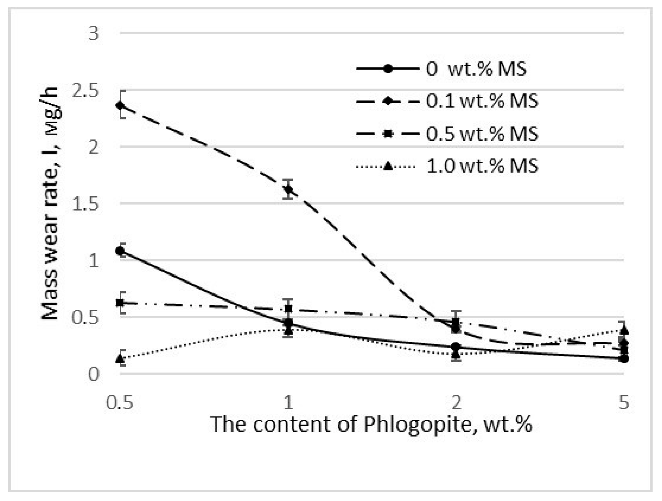
| Content of Fillers, wt.% | I 1, mg/h | f 2 | Content of Fillers, wt.% | I 1, mg/h | f 2 | ||
|---|---|---|---|---|---|---|---|
| Muscovite | MS | Phlogopite | MS | ||||
| 0.5 | 0 | 5.15 ± 0.15 | 0.22 ± 0.006 | 0.5 | 0 | 4.18 ± 0.12 | 0.24 ± 0.007 |
| 0.1 | 10.22 ± 0.30 | 0.19 ± 0.005 | 0.1 | 1.76 ± 0.05 | 0.26 ± 0.008 | ||
| 0.5 | 2.18 ± 0.06 | 0.24 ± 0.007 | 0.5 | 9.50 ± 0.28 | 0.18 ± 0.005 | ||
| 1.0 | 2.90 ± 0.09 | 0.25 ± 0.007 | 1.0 | 1.69 ± 0.05 | 0.22 ± 0.006 | ||
| 1.0 | 0 | 3.43 ± 0.10 | 0.24 ± 0.007 | 1.0 | 0 | 1.20 ± 0.03 | 0.25 ± 0.007 |
| 0.1 | 9.88 ± 2.96 | 0.19 ± 0.005 | 0.1 | 1.84 ± 0.05 | 0.23 ± 0.007 | ||
| 0.5 | 4.97 ± 0.14 | 0.21 ± 0.006 | 0.5 | 2.57 ± 0.08 | 0.22 ± 0.006 | ||
| 1.0 | 4.70 ± 0.14 | 0.20 ± 0.006 | 1.0 | 3.79 ± 0.11 | 0.18 ± 0.005 | ||
Publisher’s Note: MDPI stays neutral with regard to jurisdictional claims in published maps and institutional affiliations. |
© 2022 by the authors. Licensee MDPI, Basel, Switzerland. This article is an open access article distributed under the terms and conditions of the Creative Commons Attribution (CC BY) license (https://creativecommons.org/licenses/by/4.0/).
Share and Cite
Kapitonova, I.; Lazareva, N.; Tarasova, P.; Okhlopkova, A.; Laukkanen, S.; Mukhin, V. Morphology Analysis of Friction Surfaces of Composites Based on PTFE and Layered Silicates. Polymers 2022, 14, 4658. https://doi.org/10.3390/polym14214658
Kapitonova I, Lazareva N, Tarasova P, Okhlopkova A, Laukkanen S, Mukhin V. Morphology Analysis of Friction Surfaces of Composites Based on PTFE and Layered Silicates. Polymers. 2022; 14(21):4658. https://doi.org/10.3390/polym14214658
Chicago/Turabian StyleKapitonova, Iuliia, Nadezhda Lazareva, Praskovia Tarasova, Aitalina Okhlopkova, Samuel Laukkanen, and Vasiliy Mukhin. 2022. "Morphology Analysis of Friction Surfaces of Composites Based on PTFE and Layered Silicates" Polymers 14, no. 21: 4658. https://doi.org/10.3390/polym14214658