2.2. AM Experimental Setup
The most common design of AM hardware (3d printer) was used as a starting point for the experimental work.
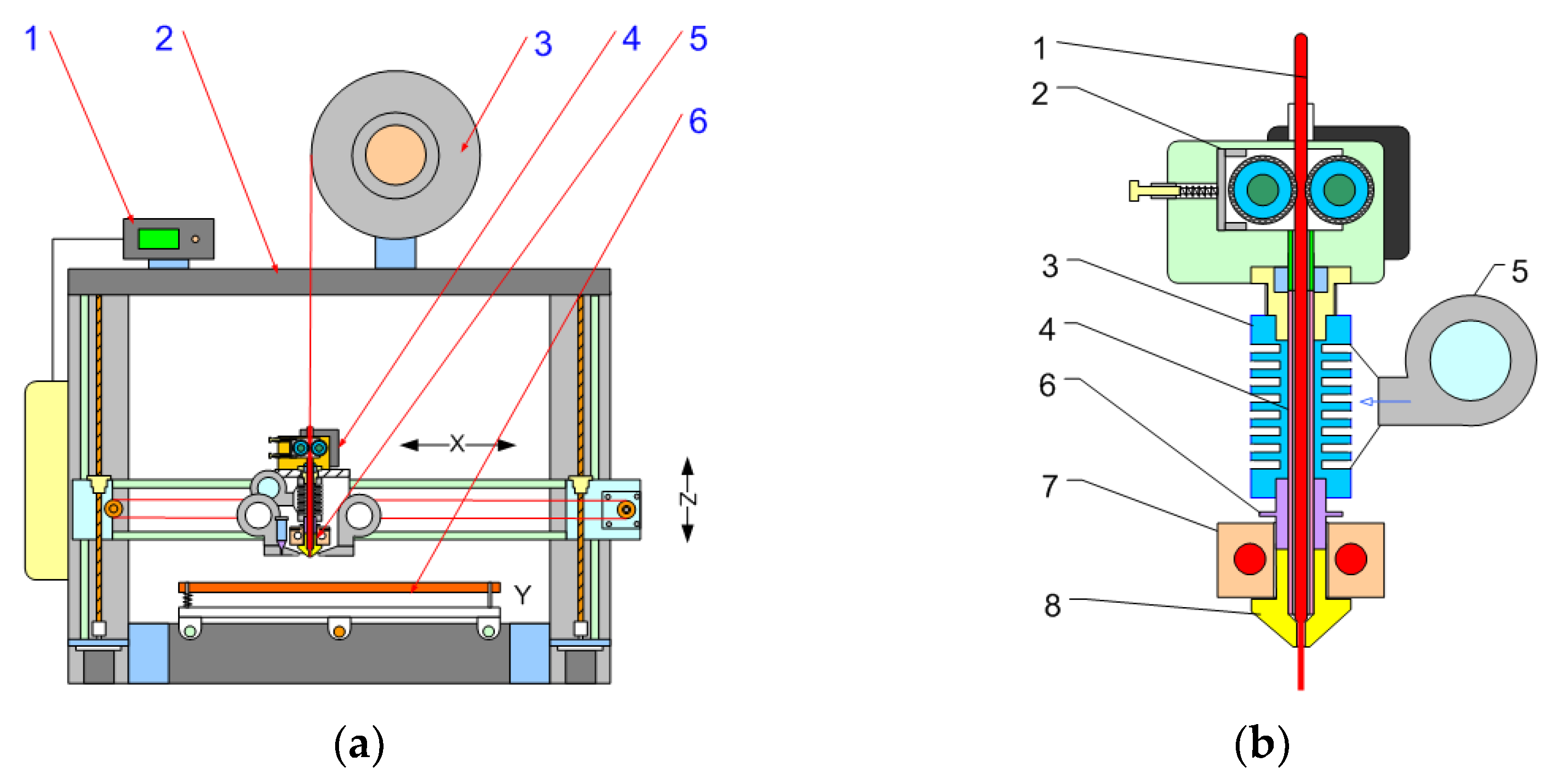
Figure 1 show the standard AM setup with an FFF extrusion system based on the filament used as a starting point.
In general, the AM setup consists of a deposition table, an extrusion system, and an axis movement system and an electronic control system. (
Figure 1a). The most specific part is the material feeding system (
Figure 1b), which consists of a mechanical roll feeder, an extruder, and a cooling device. Filament extrusion uses a ram extrusion system in which the filament is forced into an endless ram by a roller mechanism. The ram extruder melts the material in a laminar flow without mixing or homogenizing the melt, and the thermal conductivity of the material and the axial force of the ram affect the overall throughput of the process. A low internal volume and a short residual time allow the use of high processing temperatures compared with traditional screw extrusion. The extrusion line consists of two main stages—the cold stage and the hot stage. The cold stage or thermal barrier is designed for mechanical connection of the hot stage to the machine body. The hot stage is a malting chamber containing a heated block with a replaceable die. Melting of the material takes place in the nozzle body, which is surrounded by a heating block with heating elements and a temperature sensor.
During the tests, it was found that the standard extrusion line can be used for the extrusion of liquid material without any modifications. Only a mechanical seal with a high-temperature sealant is required for leak-proof operation.
The design widely known as Prusa I3 [
31], in which the deposition platform moves in the Y direction and the extrusion system moves in the X and Z directions, was converted from filament feeding to liquid feeding.
The feeding system was converted by replacement of the filament roller feeder with a liquid feeder by using a stepper motor-controlled dosing pump
Figure 2.
The control signal from the AM device motherboard was routed to an external stepper motor driver and then to the stepper motor.
The AM unit was enhanced with a quick-change device for rapidly changing extrusion dies from filament to plastisol feed, allowing both types of material to be used in the same unit. The AM build volume was 300 mm × 300 mm × 300 mm.
Various types of pumps were used for testing, but the most suitable found was asmall gear pump with a displacement of 0.15 and 0.3 mL3 per revolution. The gear pump was equipped with an adapter that allows the connection of standard pneumatic fittings with 1/8-inch thread. The gear pump shaft was connected to a standard two-pole geared stepper motor with a reduction ratio of 1 × 23. The gear pump motor was connected to a separate driver and controlled from the main board using step commands from G-code files. The extrusion speed was controlled by setting the extrusion multiplier, filament, and die diameter in the standard slicer software after recalculating the volumetric flow rate and material density.
The extrusion setup was used as a standard for the filament process with a water cooling thermal barrier. During the experiment, it was found that a water-cooled system was preferred and had higher performance. Therefore, a heat block with water cooling was used for all samples in this study. An air-cooled heat block can also be used, but at a slower feed rate. Successful operation requires a very fast temperature transition between the extruded heat block and the heat barrier to prevent clogging of the material.
The heated build platform was used without modification. Different types of coatings for the build platform were tested and evaluated to achieve adhesion of the parts. Polyvinylpyrrolidone, polyvinyl acetate, polyvinyl butyrate, and PVC polymer solutions were used. Polyvinyl acetate and PVC solutions are the most suitable.
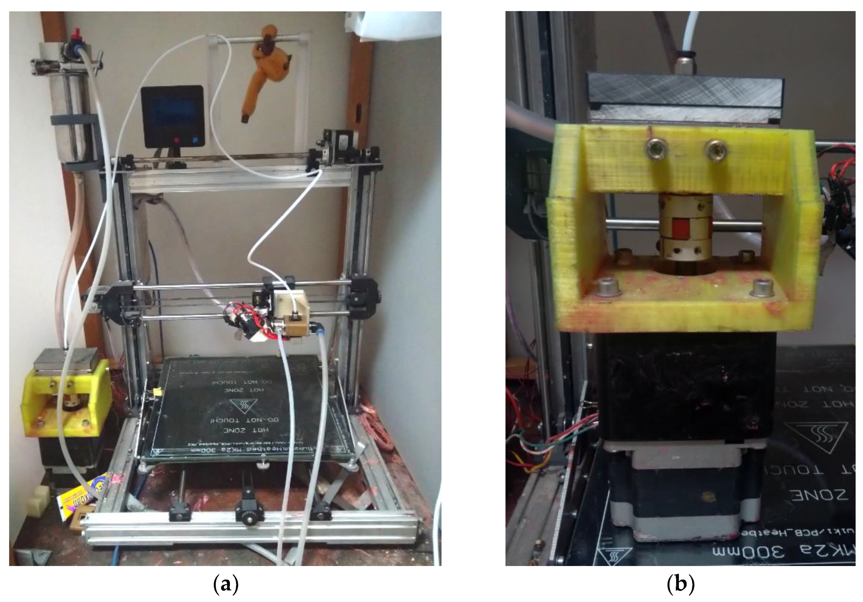
Figure 3 shows a picture of the current AM setup.
The most important process parameter is the temperature of the heated extrusion block, which was selected based on manual tests. The extrusion feed rate was calculated based on the volumetric feed rate and the characteristic volume of the gear pump and applied in the slicer software based on the filament diameter and extrusion coefficient parameters.
The conversion of the 3D model into the machine code was carried outusing the standard slicer software UltimakerCura 4.1 with manual recalculation of the feed rate.
Liquid plastisol material can be converted to flexible PVC by heating and cooling. This simple pathway consists of a chain of complex physical processes—plasticization, gel formation, melt formation, and melt cooling. The final product is a solid plasticized PVC—a thermoplastic polymer.
The main approach of the study—to complete all physical transformations of PVC plastisol—is the AM process to produce soft and elastic articles.
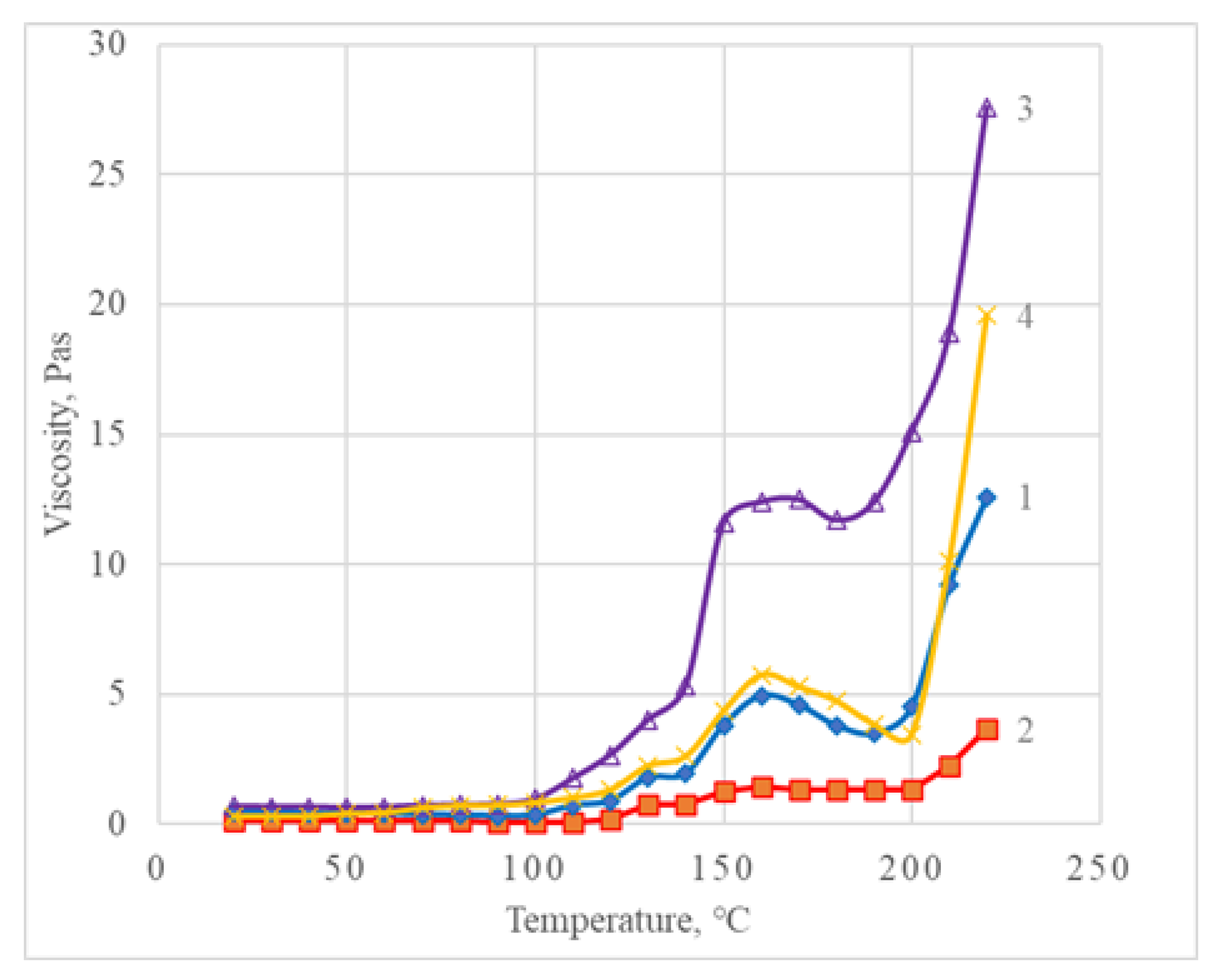
The plastisol composition for the AM process should have a certain viscosity value in order to be pumped by the selected pump type. The gear pump used in the study requires a maximum viscosity of 2–3 Pas to be pumped at hydrostatic pressure. In order to increase the maximum viscosity, a pressure chamber was used that allows plastisol with a viscosity of up to 15 Pas to be used.
Heating of PVC plastisol is accompanied by a sharp increase in viscosity. The pump pressure should be sufficient to overcome this pressure increase so that the molten material can be extruded from the die.
In the extruder system, the plastisol is rapidly heated in the heating block. During this process, the PVC suspension is converted into a viscous gel and then goes directly into the melt state. All this should be completed in a short time and with low volume to achieve low pump pressure and low residence time in the molten state. The AM experimental setup was equipped with an electronic pressure sensor in the output line of the gear pump. The material pressure was measured during extrusion at different flow rates and temperatures.
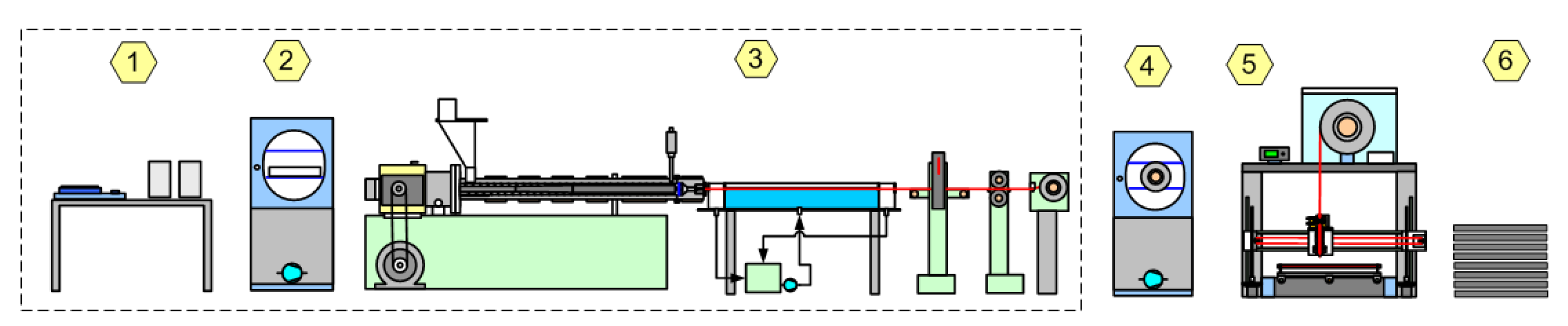
The AM process is generally highly dependent on the type and production technology of the consumables. The most widely used process is FFF AM due to the availability of filament consumables. The use of filaments in AM is simple, but the overall process including filament production from raw material is quite complex.
The production of consumables for FFF AM is quite complex and multi-step, requiring specialized equipment (
Figure 4).
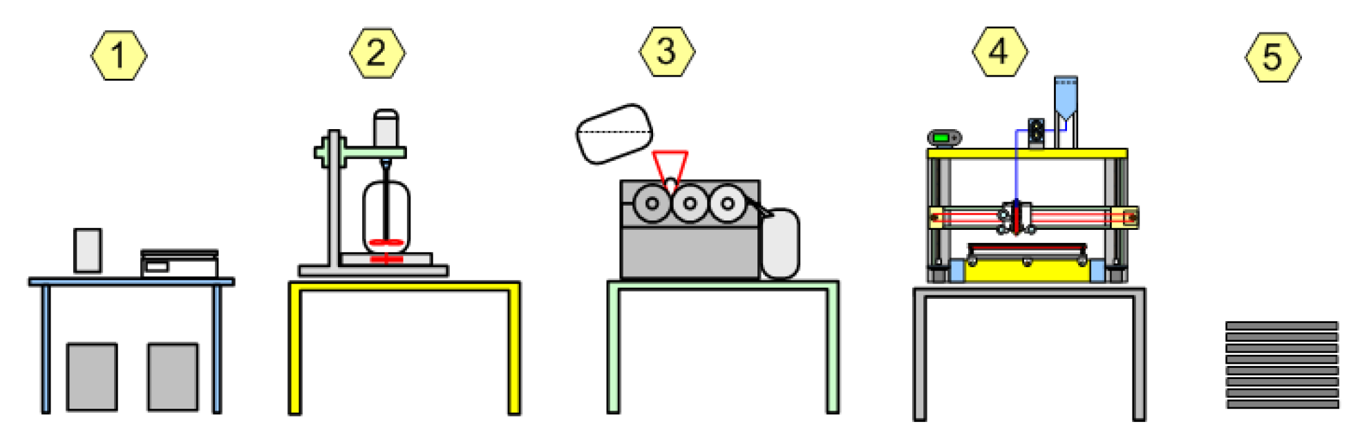
In comparison, consumables based on liquid PVC plastisol can be processed in a simpler way using conventional equipment (
Figure 5).
In the case of the introduction of different additives, the PVC plastisol process does not require additional equipment for the distribution of additives, while the filament process in this case requires a compounding step.


