1. Introduction
As defined in the SFS-EN ISO 445 standard, a pallet is a “rigid horizontal platform of minimum height, compatible with being handled by pallet trucks, forklift trucks and/or other appropriate handling equipment” and can be used “as a base for assembling, loading, storing, handling, stacking, transporting, or displaying goods and loads” [
1]. Pallets can be made of wood, plastic, aluminum and composites, and used under the three pallet management strategies of single use, buy/sell, and pooled. A pooled pallet is leased to customers without transfer of ownership. A standardized pallet is designed to last several trips, under a scheme called the “buy/sell” strategy. However, single-use pallets are the simplest strategy, as they are discarded after one trip [
2], after having been loaded with goods and transported by container ships to places all over the world. Recycled plastic pallets were found to be superior to conventional plastic pallets by an impact category analysis of the results per trip. The recycled plastic pallets also performed better in terms of environmental impact compared of wooden pallets [
3]. Single-use pallets made of recycled plastic via injection molding are the subject of this study.
Recycled plastics are based on recycled PE (rPE) and recycled PP (rPP), and they have outstanding potential. They have the potential to significantly contribute to new markets with more demanding and critical applications. One of the applications with the highest demand is found in the lower-quality end of the agricultural and building sectors, serving as a structural part [
4]. Gall et al. [
5] revealed the properties of the recycled plastics, and found that the density, melt flow rate (MFR) and Charpy impact strength of the rPP materials varied from 0.904 to 0.924 g/cm
3 (by ISO 1183), from 13 to 22 g/10 min (by ISO 1133), and from 5.9 to 6.8 kJ/m
2 (by ISO 179). The content of calcium carbonate in the rPP, analyzed by a thermos-gravimetric analyzer (TGA), ranged from 0.29 to 1.92% in mass. As they contain diverse contaminants, recyclables should be blended with legacy calcium carbonate and a polymeric cross-contaminant to modify the MFR for later applications in plastic engineering processes. One of the more common industrial plastic-processing technologies is plastic injection molding.
When using rPP in micro-injection molding, a uniaxial extension test showed that the increases in Young’s modulus, yield stress and ultimate stress values were 3.07%, 10.97% and 27.33%, respectively. A 1.29% reduction was found in the breakage strain compared to virgin PP samples [
6]. The variations in the recycled plastic’s properties may disturb the final quality of the injection part, due to the injection parameter setting remaining constant throughout the whole process. An important quality of the injection part is the warpage, which can face problems related to a combination of poor material characterization and inadequate control of the processing parameters [
7,
8,
9,
10,
11]. The temperature differences between the two mold surfaces significantly affect the morphology distributions of the molded parts. The cooling rate may affect the injection parts in terms of relaxation/reorganization levels and give rise to an asymmetric distribution of mechanical properties [
12]. An imbalance in the mold-filling is one of the factors affecting the asymmetric temperature distribution of the injection part [
13,
14]. Plastic injection molding involves four major stages: filling, packing, cooling, and ejection. The injection pressure and rate, packing pressure and time, and cooling temperature and time may affect the quality of the injection part. The mold temperature seems to be one of the main process parameters that affects the properties of molded parts [
15,
16]. Nevertheless, the mold temperature is actually unstable during the process. The temperature of the mold has never been controlled individually, as it is affected by the cooling channel and cooling time, as well as the mold opening time.
Filling the mold cavity with melted material via a gate is essential for the small injection part. Considering the limitation of the flow length from the gate, multi-gate filling can reduce a machine’s required injection parameters, and the filling time, during injection molding. Not using multi-gate filling injection is associated with a higher number of weld lines. A weld line is formed when two separate melt fronts join into one flow. Moreover, while weld lines are not appropriate for parts, it is impossible to avoid all of them due to the filling efficiency of large molding components. It is well known that the strength of weld lines is lower than the strength of the general plastic-molding material, since a lower temperature, along with air bubbles, occurs between the fronts. The structural parts molded by rPP, such as the pallet and water cage, endure the external load. The weld lines within the molded structure parts face an increased risk due to the injection molding of plastic pallets via multiple gates, whereby the melted materials flow into the mold cavity from a molding machine.
The concurrent filling of multiple gates increases the filling pressure, meaning that a larger injection molding machine is required to clamp and pack the mold during the filling and packing processes. A sequential valve gate-opening system can be used to decrease the clamping and packing forces, which divides the gates into several groups during the filling stage. Via this sequential valve gate-opening system, the flow front from the initial gates spreads to the lateral gates. The lateral gates are activated to pass on the melt material when they come into contact with the front. This approach could eliminate many weld lines from the molded part. Moreover, the scale of the injection machine can be decreased. During the injection molding of ASTM-D638 standard specimens (200 mm in length, 20 mm in width, and 2 mm in thickness) made of acrylonitrile butadiene styrene (ABS), sequentially setting the on/off times of these filling gates enabled the sequential valve gate system to eliminate the welding lines and increase the tensile strength [
17]. In addition, the different temperature levels of the melted material’s flow fronts tensile strengths, and melt polyamide flow front temperature (PA6) were correlated with the strength of the welding line [
18].
The sequential valve gate-opening system could be implemented to create large-scale plastic parts with a moderately sized injection machine. Knowing the flow front of the melt material in the mold cavity is essential for setting the switching time of all the gates in the sequential valve gate system—a theoretical model or a numerical approach could be used to predict the flow front of the injection in the mold cavity. Iwko et al. [
19] derived numerical results to verify the experimental results by constructing a comprehensive model of the plasticization process in a screw-barrel system injection molding machine. They found that the output pressure and temperature of the plasticization process, determined numerically by the model, fit the experimental results with an average error of less than 10%, but the flow front in the mold cavity was never assessed.
Cardozo [
20] reviewed the numerical approaches to filling via injection molding, and indicated that the Moldex3D software, a commercial software available for injection molding, could provide an understanding of the physical effects occurring in the mold cavity. Moldex3D was applied to investigate the molding process, while the prediction of the flow front during filling was derived from the Hele–Shaw model [
21]. The finite-volume approach was used to determine the multi-physical quantities involved in the packing and cooling processes. Furthermore, the equation governing the jetting behavior of the filling from the gate was discretized by a control volume-based, finite-volume method [
22]. By using each of the commercialized software, including ANSYS Fluent [
23,
24], Moldflow [
25], Open FOAM [
26] and Moldex3D [
10,
27,
28,
29,
30], one could analyze the multiple physical parameters of the output molding parts in relation to the operational parameters of the injection molding process. Notably, the experimental investigator could easily make a comparison between the simulation results and the real operational results in the laboratory.
Using Moldex3D, the authors undertook a numerical feasibility study of a single-use pallet created via a sequential valve gate system [
10]. However, the experimental results of this rib-structured pallet have not been determined. Differing from previous rib-structured pallets, the target pallet has a flat top surface. The aim of this study is to investigate the temperature, pressure, stress and warpage of the injection-molded rPP flat surface pallet with size dimensions of 1 m × 1 m × 0.13 m by CAE simulation and experimental methods. The results for the numerical warpage of a plastic pallet produced via a sequential valve gate system, derived by Moldex3D 2020, are compared with the real profile of the rPP pallet measured by the ATOS scan box 5120 system. Using the injection parameters of the plastic pallet, the specifications of the injection machine, and a polymer database, a fundamental investigation can be conducted to understand the injection molding process. By using a sequential valve gate-opening system to mold a plastic pallet, the flow fronts during the filling stage can be derived for an evaluation of the actuating time of the gates. A detailed understanding of the pre-setting sequence applied to the valve gates may help to determine the ideal sequence. A pre-set valve gate-opening sequence, provided by the cooperating company, would enable a comparison of the flatness of the pallet. A new proposed valve gate-opening sequence can then be used to derive an improved pallet flatness, which will help to evaluate the accuracy of the numerical predictions.
2. Experimental Setup and Software
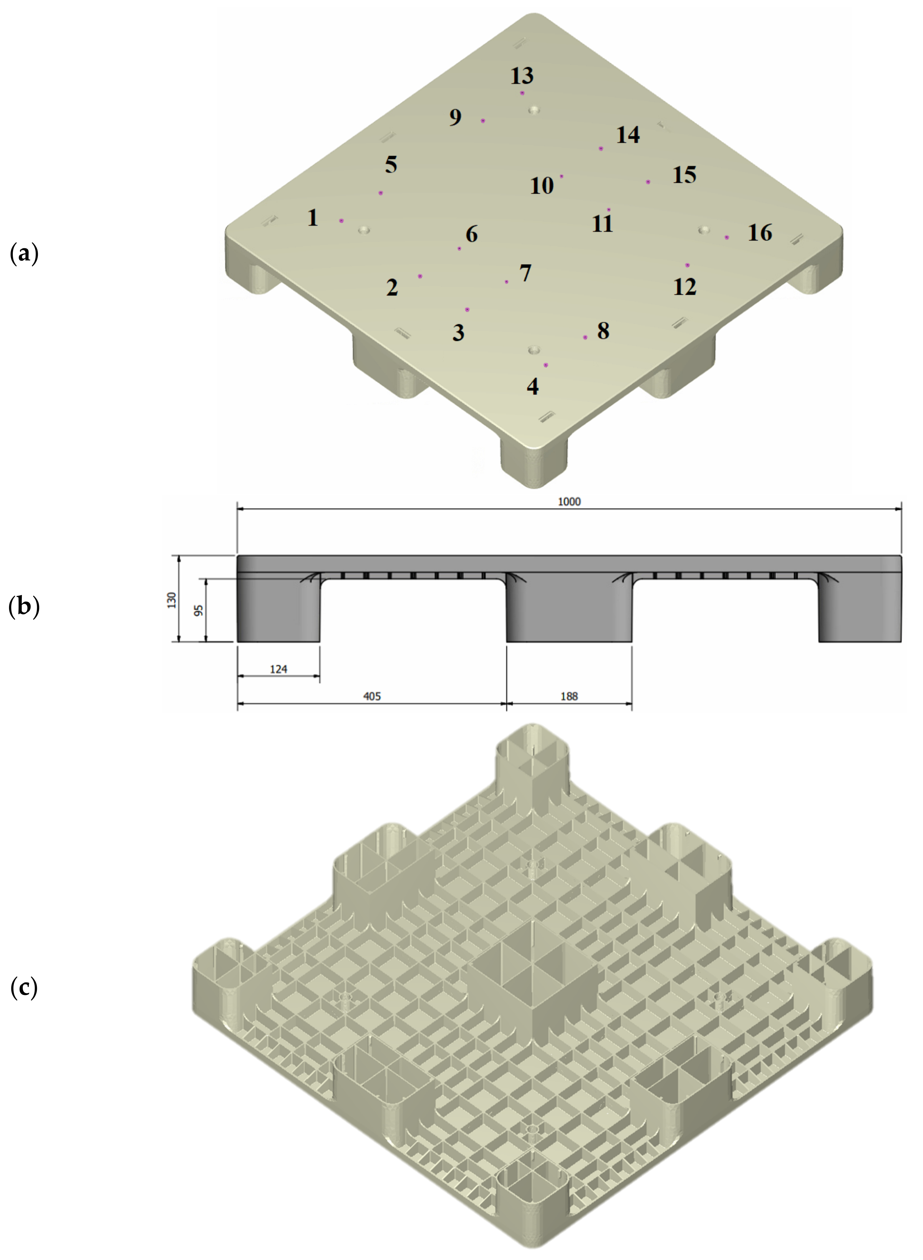
Figure 1 shows the dimensions of the plastic pallet that were used in this study. It has a flat top surface and a reinforced structure with ribs at the base. The ribs are 3 mm in thickness and were changed according to the draft angle used for the injection molding. A general rule when arranging the positions of the filling gates is to ensure that the ratio of flow length to rib thickness is below 150. When the ratio is lower than 150, the running length of the melted polymer within the mold during injection is sufficient to maintain the melting state. In this application, the maximum filling length from gates #1, #4, #13 and #16 to the four corner legs of the pallet was 394 mm. The ratio of the flow length to rib thickness in this study was 131.3, which is smaller than the general standard when arranging the positions of the filling gates. As such, there were 16 filling gates (7.0 mm in diameter and 20 mm in height), as shown in
Figure 1a. rPP was used as the injection molding plastic material to simulate real-world plastic waste reduction. The pallet’s dimensions were 1000 mm in length and width and 130 mm in height, as shown in
Figure 1b. An isometric view of the pallet’s base (
Figure 1c) shows the complex features that should be cooled during the molding process by the baffle cooling flow system, as shown in
Figure 1d. The molding experiments included sequential gate-opening and concurrent valve gate-opening systems for the melt-filling process, in order to numerically analyze the mold flow. The gates’ opening and closing were sequentially controlled by a pneumatic system, so that the previous gates were closed by relay during melt filling, and the following gates were concurrently opened—this assumes that the melted material starts to fill the mold cavity once the valve gate is completely open.
Within the simulation, the 3600-ton injection, performed by the Supermaster 3600E1 molding machine (
https://chenhsong.com/, Taoyuan Taiwan, 3 February 2022), is modeled. This molding machine has a screw diameter of 225 mm, a maximum screw stroke of 4400 mm, a maximum injection pressure of 159.7 MPa, and a maximum injection volume of 49,278 cm
3. The simulation analysis was performed using Moldex3D software. In this software, both the skin and core materials are considered to be compressible, generalized Newtonian fluids. The surface tension at the melt front is neglected. The modified Cross model with Arrhenius temperature dependence was employed to describe the viscosity of the polymer melt. During the polymer melt-filling phase, the velocity and temperature were specified at the mold inlet. While the core material was injected, the flow rate was specified at the mold inlet. On the mold wall, the non-slip boundary condition was applied, and a fixed mold wall temperature was assumed.
In Moldex3D, the finite volume method was used to discretize the Navier–Stokes equation based on the pressure-based decoupled procedure and solve the transient flow field in a complex three-dimensional geometry. A compressive, bounded, high-order differencing scheme was also utilized to directly solve the hyperbolic advection equation of the fractional volume function to track the melt front during the filling process [
21]. Modeling the flow field in Moldex3D is an iterative decoupled procedure for coupling velocity and pressure, in which the three linearized momentum equations are solved for an estimated pressure field, then sequentially followed by the solution of the pressure correction equation. The mass fluxes and pressure are then corrected. This will satisfy both local and global continuity, but can cause the momentum to deviate. Hence, a new outer iteration is activated. The process is then repeated until the prescribed tolerance for each equation is achieved [
21].
All sixteen of the valve gates are concurrently opened to allow the molten material to enter, with a hot runner used to determine the filling flow front, the clamping force, the temperature distribution, the thermal stress, and the deformation; then, the 16 gates are opened and closed in a controlled sequence. The pre-set sequence of the sequential gate-opening scheme is depicted in
Table 1. Gates 3, 5, 9, and 13–16 were initially opened to fill the mold cavity with the melted material. Gates 8 and 11 were then actuated within the first second. After this filling, gates 1, 10, and 12 were relayed. Gate 4 was turned on in the third second, and then gate 7 was activated after five seconds. Gates 6 and 2 were opened in the sixth and eighth seconds, respectively, until the end of filling. The total filling time was 9.3 s.
Using the previous setting sequence, the Moldex 3D 2020 software was used to simulate the sequential valve gate system used for the melt-filling process in the mold flow analysis. During melt-filling, the gate-opening and -closing times are sequentially controlled by the pneumatic system, so that the previous gates are closed by relay, with subsequent gates opening at the same time. This software package was also used to simultaneously open all 16 gates and direct the melted material into the mold cavity, which is the concurrent valve gate-opening scheme. The distribution of the weld lines, the filling pressure, and the estimated clamping force can also be derived. The molding analysis was then conducted for the same injection filling time via the sequential gate-opening scheme. The molding pressure within the mold cavity was measured numerically, using the same injection parameters used to set the timing control of the 16 gates. Under the sequential gate-opening scheme, the hot runners were opened at different times. Within the pallet, the temperature distributions, filling pressures, deformations and thermal stresses, as well as the shrinkages, were compared under the sequential gate-opening and concurrent valve gate-opening schemes.
During the filling stage, the fill flow front of the molten material is closely dependent on the viscosity, the material temperature, and the runner and gate of the mold. The pressure of the molten material is usually a consequence of viscosity. During the filling stage of the injection molding process, the flow front is controlled by the flow rate and pressure gradient. Adding mica powder to the rPP gives the material properties [
10] such as those shown in
Table 2, with the density of rPP being 1.026 g/cm
3, which is more than that of raw PP. In the design phase, the volumes of the plastic pallet and mold were 10,039 and 1,179.92 cm
3, respectively. The associated solid mesh of the plastic pallet, mold, and cooling channel contained 1,562,598, 4,724,368, and 4,189,448 elements, respectively. The volume and the mesh number of the 16 hot runners were 784.06 cm
3 and 839,450 elements, respectively. The surface mesh of the pallet contained 311,368 elements. The experimental viscosity with respect to the shear rate and temperature, the specific heat with respect to temperature, and the mechanical properties of the melt rPP resin were derived from Cheng [
10]. The injection molding parameters of the rPP that were used for this plastic pallet are shown in
Table 1.
It was assumed that the melted material would begin filling the mold cavity once the valve gate was completely open, and the 16 gates were opened sequentially to direct the melted material into the mold cavity. The flow fronts that occurred during short-shot testing in the injection molding of rPP pallets were compared to ensure correct simulation modeling. Then, the most suitable sequential control scheme of the gates with the same injection parameters was investigated. Via the appropriate sequential control of the gates, the filling pressures, temperature distribution, warpage deformation, thermal stresses and shrinkages were assessed to determine the advantages of this analysis.
The rPP pallet molded by the Supermaster 3600E1 molding machine is 1 m in length and width and 0.13 m in height. This pallet scale is too large to measure its three-dimensional profiles using a general coordinate measuring machine (CMM). The ATOS scan box 5120 system (GOM, Swiss,
www.gom.com, 3 February 2022) is a non-contact three-dimensional measuring system that operates via high-speed sensors used to scan all the parts. A 3D graph could be generated from these scans for 3D printing, reverse engineering or part inspection. The injection-molded pallet was measured by RATC in Taiwan (
https://www.ratc.com.tw/, 3 February 2022) with ATOS scan box 5120. The authors imported the 3D graph generated by the ATOS scanning system into Creo Parametric CAD to calculate the flatness of each surface on the pallet. The measured flatness and the profile of the pallet’s surface were compared with the numerical results derived by Moldex3D.


