Abstract
Fiber-reinforced polymer (FRP) composites have been widely used for strengthening or constructing structures due to their excellent corrosion resistance and high tensile strength. An emerging hybrid structural member form with FRP composites—which consist of a steel section as internal reinforcement, an external FRP wrap/tube, and concrete filled between them (referred to as FRP-confined steel-reinforced concrete (FCSRC) systems)—has attracted increasing research interest. To date, the concept has been adopted to strengthen/repair steel structures or used as new hybrid structural members (e.g., hybrid columns or beams, including buckling restrained braces (BRBs)). The FRP confinement and composite action between the three components in FCSRCs result in the excellent performance of the hybrid member. This paper presents a state-of-the-art review of FCSRCs for structural applications. The gaps in knowledge and future research opportunities on FCSRC structural members are also identified.
1. Introduction
Fiber-reinforced polymer (FRP) composites have been widely used as alternatives to steel reinforcement or strengthening materials in engineering structures due to their excellent corrosion resistance and tensile properties [1,2,3,4,5,6,7,8,9,10,11,12,13,14,15]. However, FRP composites also have many limitations including high costs, a low elastic modulus, and a lack of ductility. Therefore, it is generally not an economic option to construct pure FRP structures in practical applications. To this end, the combined usage of FRP composites and traditional construction materials (including steel and concrete) has attracted more and more attention in the research community [16,17,18,19,20,21,22,23,24,25,26,27,28,29,30,31], with the aim to establish cost-effective and novel forms of structures with excellent structural performance.
Among the various novel forms of hybrid structural members containing FRP composites, one of the most common is concrete-filled FRP tubes (CFFTs; Figure 1), in which the FRP tube provides passive confinement to the concrete core under compressive loading and further improves both the strength and deformation capacity of the concrete. Subsequently, capitalizing advantages of the FRP-confined concrete, steel reinforcement has been proposed to be used in FRP-confined concrete structural members to further enhance their deformation capacity and strength. Among these hybrid structural members, double-skin tubular members (DSTMs; see Figure 2a) [16,17,18,19,20] are popular. However, the DSTMs—which consist of an FRP tube as an external confining device and protective skin against environmental attacks, a steel tube as internal reinforcement, and concrete sandwiched between the two tubes—may experience the inward buckling of the steel tube under compression. To address this concern, some investigators have proposed filling the inner void of DSTMs to form the hybrid double-tube concrete members (DTCMs; see Figure 2b) [21,22,23,24,25,26,27]. Additionally, an emerging form of hybrid systems with FRP composites termed as FRP-confined steel-reinforced concrete structural members (FCSRCs; see Figure 3) [32,33,34,35,36,37,38,39,40,41,42,43,44,45,46,47,48,49,50,51,52,53,54,55,56,57]—which consist of a steel section as internal reinforcement, an external FRP confining tube, and concrete filled between them—has recently attracted increasing research interest.
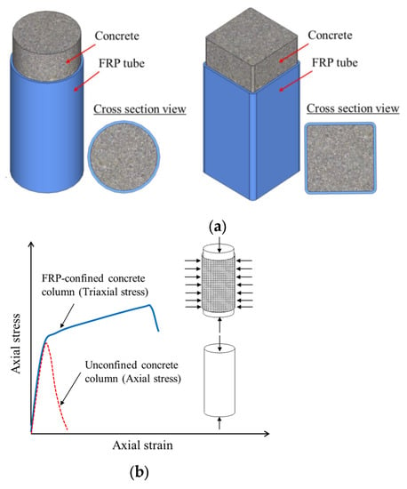
Figure 1.
Concrete-filled FRP tubes (CFFTs). (a) Different shapes. (b) Performance improvement mechanism.
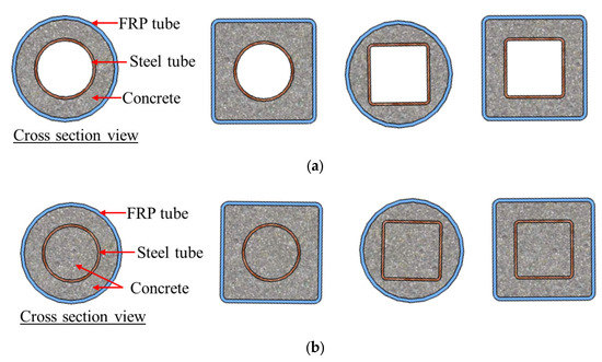
Figure 2.
Double-skin tubular members (DSTMs) and double-tube concrete members (DTCMs). (a) Double-skin tubular members (DSTMs). (b) Double-tube concrete members (DTCMs).
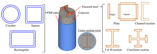
Figure 3.
Different configurations in FRP-confined steel-reinforced concrete (FCSRC) members.
The concept of FCSRC structural members was first proposed by Liu et al. [32] with the aim to strengthen/repair steel structures. Compared to conventional steel–concrete composite structural members or CFFT structural members, FCSRC structural members have the following advantages: (i) FRP wraps/tubes provide confinement to the concrete and prevent the possible buckling of the internal steel section so that both the concrete and the encased steel section substantially contribute to carrying the axial load; (ii) FRP tubes act as a stay-in-place formwork for the concrete and protect the steel and the concrete against corrosion; (iii) the steel section replaces the longitudinal steel reinforcement in traditional reinforced concrete (RC) members and provides additional shear and compressive capacities; and (iv) connections to the superstructures and foundations can be easily achieved due to the presence of a steel section in FCSRCs.
Up to date, FCSRC systems have been adopted to strengthen/repair steel structures [32,33,34,35,36,52,55] and as new hybrid structural members (e.g., hybrid columns, beams [37,38,39,40,41,42,43,44,45,46,47,48,49,50,51,53,54,56,57], or buckling restrained braces (BRBs) [58,59,60,61,62,63,64,65,66,67,68]). Extensive studies have been carried out to understand the performance of such forms of hybrid structural members, and they have been shown to have excellent performance. However, the current research related to hybrid systems has also not been carefully summarized, and further studies on FCSRC structural members are necessary for FCSRCs to be widely used in applications. To this end, this paper presents a state-of-the-art review of FCSRC structural members in strengthening steel structures/constructing new structures. The gaps in knowledge and future research opportunities on FCSRC structural members are also identified.
2. Development of FCSRC Structural Members
The concept of FCSRC structural members was first proposed by Liu et al. [32] to strengthen corroded I-shaped steel columns. In their study [32], a total of seven steel columns, in which five FCSRC specimens were notched to simulate the section loss caused by steel corrosion, were tested. The experimental results showed that the proposed FRP retrofitting technology for steel columns was feasible: the axial compression capacity of the reinforced steel column was significantly higher than that of the unreinforced steel column due to the confinement from the concrete and the FRP tube. In addition, as recommended by Liu et al. [32], the fabrication scheme of the FRP jacket was not limited to the FRP-wrapping-based wet layup process (i.e., FRP wraps). They can also be manufactured by bonding the separated FRP tubes together with epoxy to form an onion-skin jacket around existing steel columns (see Figure 4) in retrofitting applications, as placing the continuous FRP tube around an existing steel column is often difficult due to the interference of other structural elements. The capabilities of hybrid systems constructed with continuous and split FRP tubes are assumed to be similar provided that the bond strength between the epoxy and the FRP tube is efficient. Subsequently, the so-called onion-skin retrofitting technique was suggested to be applied to strengthen existing steel columns [33,36,37]. It should be mentioned that Karimi et al. [37] still utilized the continuous FRP tubes, and only Linde et al. [36] applied the typical retrofitting system to an existing I-shaped steel column. As shown in Figure 5a, a glass FRP (GFRP) tube was first cut into two half tubes, and then the two half tubes were brought together to surround an existing steel section. Next, carbon FRP (CFRP) sheets were wrapped around the split GFRP tube to create a continuous GFRP tube via a wet layup process. Finally, the concrete was cast into the void between the steel section and the FRP tube. Based on the experimental results, Linde et al. [36] concluded that the ultimate capacity of the composite columns could be significantly enhanced by using the proposed split-tube retrofitting technique, although the columns finally failed by FRP rupture at the gap in the GFRP tube that was externally wrapped with two plies of CFRP sheets (i.e., the weak point in the cross section) (see Figure 5b).
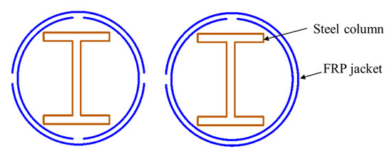
Figure 4.
Fabrication schemes of FRP jackets.
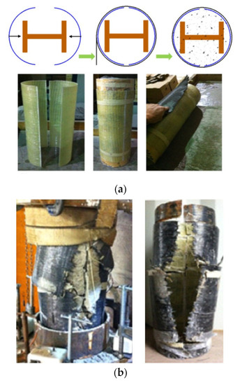
Figure 5.
Fabrication schemes of FRP jackets (reproduced with permission from ref. [36], copyright American Society of Civil Engineers 2015 ). (a) Split-tube construction process. (b) Typical failure modes.
In addition to their use as a rehabilitation technique for steel structures, FCSRC systems have also gradually developed into significant structural elements in new structures (e.g., hybrid columns or beams). In such a hybrid structural member, the prefabricated FRP tube not only acts as a confining device but also serves as an in-site formwork for casting concrete. Moreover, both the confinement provided by the FRP tube and the support from the surrounding concrete can effectively restrain local and overall buckling of the internal steel section, leading to the full exploitation of the load-carrying capacity of the steel section. In general, structural capabilities are similar whether FCSRC systems are used for structural repairing/strengthening or new construction. Currently, a number of experimental and theoretical investigations have been conducted to gain an in-depth understanding of the behavior of this novel form of hybrid member under various loadings (e.g., concentric compression, eccentric compression, and bending) [32,33,34,35,36,37,38,39,40,41,42,43,44,45,46,47,48,49,50,51,52,53,54,55,56,57]. This paper summarizes the experimental research associated with FCSRC systems in strengthening/repairing steel columns or constructing new structures (Table 1). As presented in Table 1, previous studies have mainly focused on the behavior of FCSRC columns subjected to concentric or eccentric compression. The investigated parameters varied and included the sectional configuration, the type of the three constituent materials, the slenderness ratio, and the load eccentricity.

Table 1.
Summary of studies on FCSRC columns under axial compression.
On the other hand, the concept of FCSRC systems has been applied to the buckling restrained braces (BRBs) that are commonly used as passive energy dissipation devices in seismic zones (i.e., stabilizing steel braces with FRP reinforcements) [58,59,60,61,62,63,64,65,66,67,68]. As shown in Figure 6, in such a form of BRBs, FRP composites are often used as the external shell, which can provide confinement to improve the buckling behavior and ultimate strength of the steel core. Additionally, the filling materials in this form are not limited to concrete; contrarily, they are often replaced by other light-weight materials (such as self-consolidating grout, cement mortar, or bamboos splints) that are intended to restrain the buckling of the steel core not resisting the applied loads. Moreover, lubricants or isolation materials are often used to eliminate the bond and friction between the steel core and the filling materials, as well as the bond between the filling materials and the external FRP wrap/tube [62,64]. The goals are to ensure ductile failure of the brace and to avoid the cracking of the filling materials subjected to loadings, which would weaken the lateral buckling support. However, some researchers have allowed the fillers to bond directly to the steel core [59]. Some attempts have been made to verify the feasibility of FCSRC systems in BRB applications. Table 2 provides a summary of studies on FCSRC BRBs, and the following sections present a comprehensive review of the relevant works of BRBs with FCSRC systems.
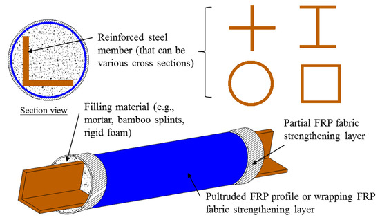
Figure 6.
Different configurations in FCSRC BRBs.
Table 2.
Summary of studies on FCSRC BRBs.
3. Applications in Strengthening Existing Structures/Constructing New Structures
3.1. Different Configurations
As shown in Figure 3, both the steel and the FRP wrap/tube in FCSRCs can be designed with different cross-sectional shapes. Generally, different cross-sectional shapes of the two components (i.e., the steel and the FRP wrap/tube) have different effects on the structural performance of FCSRCs. For instance, circular wrap/tube can provide more sufficient confinement to concrete than the square or rectangular wrap/tube. To this end, this section comprehensively reviews the latest innovative studies of FCSRCs with different configurations, providing reference for follow-up research and practical applications.
3.1.1. Cross Section Shape
In building construction, square or rectangular columns may be preferred to circular columns due to aesthetical and other reasons. However, it is well-known that not all the concrete in a square or rectangular FRP tube is effectively confined, especially the concrete close to the flat sides. This hinders the application scope of FRP-confined concrete columns with a non-circular cross section. As shown in Table 1, most studies on FCSRC columns have focused on circular columns. The structural performance of the non-circular FCSRC columns with profile steel has also been explored [34,35,39,42,44,45,46,50]. Generally, circular FCSRC columns are superior to non-circular FCSRC columns in terms of the load-carrying capacity if other parameters are identical and the difference between them is attributed to the different confinement mechanisms of the concrete in circular and non-circular FRP tubes.
3.1.2. Steel Shape
I- or H-Section Steel
I-shaped (or H-shaped) steel sections are one of the most common forms in steel structures, and they have recently been used in FCSRC columns (see Figure 7) [32,34,35,37,38,39,40,41,43,46,47,48,50,52,53,55,56]. Previous studies on FRP-confined concrete-encased I-section steel columns have indicated their excellent ductility under various loading scenarios (e.g., concentric compression and eccentric compression). In such a sectional configuration, the buckling of I-section steel (especially overall buckling) can be restrained so that the post-yield strength of the steel can be fully exploited and the concrete is effectively confined by the external FRP confining device. Most importantly, the I-section steel may suppress the lateral expansion of the in-filled concrete because the two flanges are connected by the web and its confinement level is depended on the flexural stiffness of the flanges and the axial stiffness of the web [50]. This explains why both the load-carrying capacity and deformation capacity of FCSRC columns are superior to those of bare steel columns and steel-reinforced concrete columns (see Figure 8a). Yu et al. [50] reported that a combination of the three constituent materials (i.e., FRP, concrete, and steel) in this form of hybrid system achieved beneficial interactions between them (see Figure 8b). In addition, longitudinal reinforcing bars have sometimes been embedded to compensate for the loss of the weak-axis bending stiffness and increase the capacity of corroded and buckled steel columns [52,55].
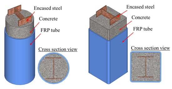
Figure 7.
FCSRC columns with I or H-section steel.
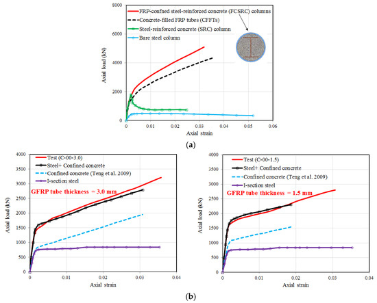
Figure 8.
Axial load–axial strain curves of FCSRC columns with I-section steel under concentric compression (reproduced with permission from Chen et al. [41] and Yu et al. [50], published by Eng. Struct. 2020, 220, 110990, and Compos. Struct. 2016, 154, 493–506, respectively). (a) Chen et al. [41]; (b) Yu et al. [50].
In most cases, I- or H-shaped steel columns are fully encased by the concrete and the composite columns are fully confined by an FRP jacket along with the column height [32,36,37,38,39,40,41,43,47,48,50,52,53,55,56]. On the other hand, some scholars have also investigated the partial encasement mode of the steel section and different strengthening techniques of the FRP jacket in FCSRCs with I-section steel (see Figure 9) [34,35,46]. For instance, in the studies of Karimi et al. [34,35], the steel section in the rectangular columns was partially encased by concrete and the entire composite column section was fully wrapped with an FRP jacket (see Figure 9d). They found that the compressive behavior (e.g., strength, elastic axial stiffness, and deformation capacity) of the partially encased steel columns could be significantly enhanced with the increase in either the thickness or the corner radius of the FRP tube. However, no studies have reported differences in full and partial encasement modes for I- or H-section steel in FCSRC columns to date. The flanges of the steel section that are not effectively supported by concrete may be more prone to buckling than that of the fully encased steel section, leading to the premature rupture of the FRP jacket. Note that Karimi et al. [37,38] adopted the prefabricated FRP tube instead of the FRP wrap. They also accounted for the load-carrying capacity of the FRP tube (as elastic materials) when evaluating the ultimate strength of the composite columns. Liang et al. [46] adopted the same strengthening device as Karimi et al. [34,35] for steel columns (i.e., partial encasement mode), but they adopted FRP partial wrapping strengthening schemes for entire composite columns (see Figure 9c). They conducted a series of experimental studies to understand the compressive behavior of CFRP partially wrapped steel-reinforced concrete stub or slender columns. The results showed that CFRP strips could improve the ultimate strength and stiffness of partially concrete-encased steel columns and effectively delay the local buckling of profile steel. These results indicate the feasibility of using CFRP strips to confine partially concrete-encased steel columns.
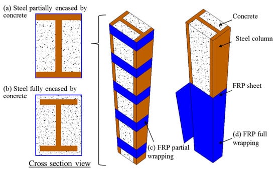
Figure 9.
Schematic of composite columns. (a) Steel partially encased by concrete; (b) Steel fully encased by concrete; (c) FRP partial wrapping; (d) FRP full wrapping.
Cruciform Section Steel
Studies on FCSRC columns with a cruciform steel section have been limited (see Figure 10) [41,42,44,45,47,49]. This form of composite columns was first proposed by Huang et al. [42]. Compared to I-shaped steel, the cruciform section steel with two pairs of flanges connected by the webs provides a more effective confinement to the concrete, which can compensate for the insufficient confinement from the FRP of the concrete near the four flat sides of a square section. The cross-shaped steel section is also particularly advantageous for columns carrying loads in two lateral directions. It should be pointed out the studies of Huang et al. [42,44,45] focused on square FCSRC columns, where the cruciform section steel was partially encased by the concrete (i.e., there was no concrete cover between the steel flange and the FRP tube). In addition, Huang et al. [42,44,45] investigated the effects of the flange width, flange thickness, web thickness, and FRP tube thickness on the compressive behaviors of FCSRC columns via experimentation. Similar studies have also been conducted by Chen et al. [41], Ren et al. [47], and Xiong et al. [49] on the compressive behavior of circular FCSRC columns. The test results from Huang et al. [42] confirmed the superior performance of FCSRC columns with cruciform steel: the buckling of the steel section was effectively prevented (which was consistent with the findings of Ren et al. [47]), contributing to a ductile response of the composite column, and both the compressive strength and ultimate axial strain of the confined concrete in square FCSRC columns were superior to those in circular CFFTs with an identical internal cross section and the same FRP tube. That is, the axial strength of an FCSRC column was larger than that of the sum of the strengths of the CFFT column and the cruciform section steel column due to the additional confinement and stability of the steel columns. Moreover, Ren et al. [47] reported that the load capacity of FCSRC columns was very close to the summed loads of a CFFT column and a steel column without buckling behavior.
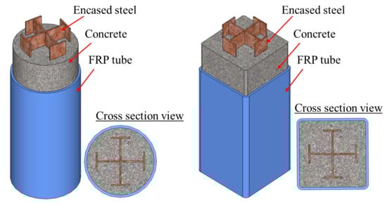
Figure 10.
FCSRC columns with cruciform section steel.
Channel Steel and Steel Plate
In comparison with I-shaped steels and cruciform section steels, channel steels and steel plates are less popular in FCSRC columns due to the asymmetry of their cross sections and other reasons. To the authors’ best knowledge, only He and Chen [54] and Yu et al. [51] have conducted experimental studies on the compressive behavior of FCSRC columns with a channel steel section (Figure 11) or a steel plate (Figure 12), respectively. He and Chen [54] investigated the effects of concrete strength grade, the steel ratio, and the diameter-to-thickness ratio of the GFRP tube. They found that in addition to the ultimate load capacity and initial stiffness, the deformation capacity of the composite column increased with the concrete strength, but Xie et al. [56] reported that I-section steel-reinforced CFFT specimens with a higher concrete strength had a lower deformation capacity. Moreover, the variation in the steel ratios had a negligible effect on the deformation of the FCSRC column with channel steel [54], which was consistent with the findings of Xie et al. [56].
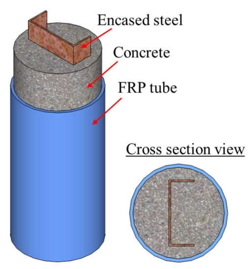
Figure 11.
FCSRC columns with channel steel.
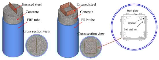
Figure 12.
FCSRCs with a single steel plate or multiple steel plates.
In addition, in the study of Yu et al. [51], encased high-strength steel plates were connected by bolted angle brackets at discrete heights (see Figure 12). The novelty of the proposed method is that welding was not involved in the fabrication of high-strength steel profiles, thus reducing the manufacturing and transportation costs and avoiding the perceived difficulties associated with welding high-strength steel sections, leading to a simpler structural design procedure. The test results from Yu et al. [51] demonstrated that the buckling of steel plates with a yield stress of 455 MPa could be well-prevented by the encasing concrete before and after the rupture of the FRP tube, and the FCSRC columns possessed a good ductile responses under concentric and eccentric loadings. Moreover, no buckling of the steel plate was observed in the FCSRC columns with a single plate after the respective FRP tube ruptured at a large deformation, so they concluded that the occurrence of buckling of the square plates before the rupture of the FRP tube may have been affected by the thickness of the concrete cover, though this has not been verified to date.
3.2. New Types of Materials Used in FCSRC Columns
3.2.1. FCSRC Columns with LRS FRP Tube
FRP composites can be classified into two types according to their tensile strain capacity: large rupture strain (LRS) FRPs (up to 8%) and small rupture strain FRPs (i.e., conventional FRPs). Conventional FRPs include CFRPs, GFRPs, aramid FRPs (AFRPs), and basalt FRPs (BFRPs). Generally, CFRPs have the highest ultimate strength and modulus of elasticity, while BFRPs have the lowest ultimate strength and modulus of elasticity, as shown in Table 3. In terms of strain capacity, CFRPs generally have a lower ultimate strain than BFRPs and GFRPs. On the other hand, the fibers utilized in LRS FRPs include PA (polyacetal), PEN (polyethylene naphthalate), and PET (polyethylene terephthalate) fibers, and the respective composites are referred to as PA FRPs, PEN FRPs, and PET FRPs, respectively. Slightly different from conventional FRPs, LRS FRPs possess a large rupture strain and a much lower modulus of elasticity. In particular, LRS FRPs exhibit an approximately bilinear tensile stress–strain behavior, while conventional FRPs are linear-elastic materials. As shown in Table 1, recent studies have mainly focused on FCSRC columns using GFRPs and CFRPs. Huang et al. [43] investigated FCSRC columns with PET FRP tubes. The results showed that the axial deformation capacity of PET FCSRC columns (an ultimate axial strain of above 0.075) was much better than that of FCSRC columns with a GFRP tube (an ultimate axial strain of around 0.012). Although the columns had experienced sustainable deformation, the local buckling of the embedded I-shaped steel was still restrained by the surrounding confined concrete and the steel section may provide additional confinement, results consistent with the findings of Huang et al. [42].
Table 3.
Typical properties of various fibers in FRPs (data from manufacturer).
3.2.2. FCSRC Columns with High-Strength Steel
High-strength materials are often preferred when the weight and/or size of structures needs to be reduced. However, the use of high-strength materials has so far been rather limited because they significantly reduce the ductility of members. High-strength steel (generally refers to the steel with a yield strength greater than or equal to 450 MPa) is more susceptible to buckling failure than normal-strength steel. Such buckling failure should be avoided in structures because it portends that the yield strength of high-strength steel cannot be fully utilized and the ductility of the structural member can be greatly compromised. Efforts have been made to prevent or delay the local and overall buckling of steel in structural columns, such as (i) filling a steel tube with concrete [69,70,71], (ii) filling the annular space between the steel tube and the FRP tube for double-skin tubular columns (DSTCs) [16,17,18,19,20], (iii) implementing an FRP wrap on the concrete-filled steel tubes [72,73,74,75,76], and iv) encasing a steel section (e.g., tube shape or I-section) by concrete [77,78,79,80] or FRP-confined concrete [21,22,23,24,25,26,27,32,33,34,35,36,37,38,39,40,41,42,43,44,45,46,47,48,49,50,51,52,53,54,55,56,57]. However, each technique may have limitations: (i) for the first one, the local outward buckling of the steel tube still occurs due to incompatibility with concrete (the Poisson’s ratios of concrete and steel are 0.18 and 0.3, respectively); (ii) for the second one, the possible inward buckling of the steel tube remains a potential issue for DSTCs; and (iii) for the third and fourth ones, the steel section may be less likely to buckle prior to the cracking of concrete (or the FRP tube rupture) because it is surrounded by the concrete or constrained by the FRP jacket. Recently, Yu et al. [51] adopted a high-strength steel section in FCSRC columns (i.e., corresponding to the fourth one) (Figure 12). It was demonstrated that the buckling of steel plates with a yield stress of 455 MPa could be well-prevented by the encasing concrete and the plates’ yield strength could be fully utilized in FCSRC columns, leading to excellent structural responses. Therefore, high-strength steel is recommended for FCSRC columns, though further experimental works are still needed to validate its feasibility in the near future.
3.2.3. FCSRC Columns with New Types of Concrete
In recent years, scholars have extended the in-filled concrete in FCSRC columns from ordinary concrete to new types of concrete (e.g., high-strength concrete, recycled aggregate concrete, and expansive concrete), which has considerably expanded the application scope of FCSRC columns. The following sections summarize the latest studies on FCSRC columns with new types of concrete.
High-Strength Concrete
High-strength concrete (with a compressive strength of 50–120 MPa) has become increasingly attractive due to its high strength and high modulus of elasticity. Previous studies have revealed that FRP confinement can improve both the strength and ductility of high-strength concrete; however, a strain-softening segment often appears in the stress–strain behavior of FRP-confined high-strength concrete. The interaction between the encased steel and the high-strength concrete confined with FRP is also an important issue to be explored for FCSRC columns. Up to date, there have been few studies on the compressive behavior of FCSRC columns using high-strength concrete [41,53]. In the study of Ozbakkaloglu and Fanggi [53], two FCSRC columns with high-strength concrete of 102.9 MPa were tested just as reference specimens for DSTCs. It was revealed that the concrete in FCSRC columns exhibited a slightly lower strength than that of the DSTCs, indicating good confinement from the external FRP confining tube. In the study of Chen et al. [41], four FCSRC columns with high-strength concrete of around 110 MPa were tested. It was demonstrated that the high-strength concrete produced a higher axial stiffness and a higher axial compressive capacity for the FCSRC columns than the normal-strength concrete, but it weakened the deformation capacity of the composite column. These findings were consistent with those of previous studies [14,15,16,17,18,19,20,21,22,23,24,25,26,27].
Recycled Aggregate Concrete
Extensive research have been carried out to understand the material and structural performance of recycled aggregate concrete [81,82,83,84], and some design methods have been proposed for structural members with recycled aggregate concrete [85,86]. However, the use of recycled aggregate concrete is still limited to non-structural elements due to its inherent drawbacks (e.g., higher water absorption, weaker interfacial transition zones, lower strength, and lower stiffness). Notwithstanding, it has been proven that both the strength and deformation capacity of recycled aggregate concrete can be improved by FRP confinement [84]. Recently, some researchers used recycled aggregate concrete in FCSRC columns [48,49]. Xiong et al. [49] explored the effects of the replacement ratio of recycled coarse aggregates and the FRP confining stiffness on circular FCSRC columns with a cruciform steel section. It was found that FCSRC columns with recycled aggregate concrete had similar compressive behavior to those with ordinary concrete, but the use of recycled aggregate concrete slightly decreased the load-carrying capacity of the column and led to a low concrete dilation at a certain axial deformation in the strain-hardening segment. In contrast to Xiong et al. [49], Ren et al. [48] applied recycled aggregate concrete to a circular FCSRC column with an I-shaped steel section and focused on the behavior of the slender columns under eccentric compression. They found that with the exception of the ultimate load-carrying capacity, the buckling behavior of slender FCSRC columns was hardly affected by the replacement ratio of recycled aggregate concrete. Additionally, the load-descending rate tended slow as the replacement ratio increased.
Expansive Concrete
It is well-known that FRPs provide passive confinement to concrete cores subjected to lateral dilation [12,13,14,15]. Thus, concrete shrinkage and stress hysteresis could weaken the utilization ratio of FRP confinement. In this case, it is recommended to use expansive concrete to provide a small amount of active confinement [87,88,89]. Recently, several researchers adopted expansive concrete in FCSRC columns to generate active pre-stress for strengthened steel cores [32,36,37,39,40,52]. Liu et al. [32] first proposed to use expansive light-weight concrete as the filling materials of wrapped steel columns. Their results revealed that the composite columns using expansive concrete-generated pre-stress had an increase in the ultimate load capacity compared to the control specimens (i.e., composite columns made with non-expansive light-weight concrete). Subsequently, Karimi et al. [37] and Linde et al. [36] undertook experimental investigations to explore the effect of concrete shrinkage on confined concrete and composite columns. It was found that the addition of a shrinkage reduction agent had a significant effect on the confined concrete strength and the compressive behavior of composite columns was greatly improved. Cao et al. [39,40] incorporated expansive concrete in the square and circular FCSRC columns, and they found that the pre-stress generated from the expansive concrete could eliminate the stress lag and that the strength of expansive concrete-based FCSRC columns was higher than that of ordinary concrete specimens.
3.3. Behavior of Slender FCSRC Columns
Different from stub FRP-confined composite columns, slender FRP-confined composite columns encounter secondary bending moments, which reduce their load-carrying capacity. This is because the increased slenderness changes the failure mode of the column from a loss of cross-sectional strength to a loss of member stability, thus leading to a reduction in the FRP confinement efficiency. Therefore, the effect of column slenderness on the compressive behavior of columns is an important issue to be addressed. To the best knowledge of the authors, most of the research on FCSRC columns has focused on stub columns, and studies on slender FCSRC columns are limited [35,38,44,46,48,50]. The following sections review the state-of-the-art studies of the buckling behavior of slender FCSRC columns under concentric or eccentric loadings.
3.3.1. Concentrically Loaded FCSRC Columns
Karimi et al. [35,38] investigated the influence of the slenderness ratio on the behavior of rectangular FCSRC columns. As expected, the load-carrying capacity of the composite columns and the beneficial effect from the FRP confinement both decreased with an increase in the slenderness ratio. A similar finding was also reported in the study of Liang et al. [46]. In particular, as observed by Karimi et al. [35,38], the FRP confinement was invalid in composite columns with a slenderness parameter () greater than 1.0 due to the elastic overall buckling of the column prior to confinement activation. However, as these studies were aimed at strengthening the damaged steel columns, the performance of the long composite columns (e.g., the strength, the axial stiffness, and the energy capacity) was still significantly enhanced compared to the bare long steel columns.
3.3.2. Eccentrically Loaded FCSRC Columns
In practical applications, columns are inevitably subjected to combined compression and bending. The load-carrying capacity of a column is generally reduced by a bending moment due to uneven stress distribution. Huang et al. [44] investigated the effects of the slenderness ratio and load eccentricity on the compressive behavior of slender FRP-confined concrete-encased cross-shaped steel columns. The results indicated that the load-carrying capacity of FCSRC columns decreased with the slenderness ratio and the load eccentricity, as expected; however, the lateral deformation at the ultimate state (i.e., at the time of FRP rupture) increased with the slenderness or the load eccentricity. Moreover, Ren et al. [48] reported that slender FCSRC columns under eccentric loadings experienced different failure modes in compression zones compared to short FCSRC columns. For the former, the failure was governed by matrix rupture, while the failure modes of the latter varied from hoop rupture to matrix rupture with the increase in eccentricity.
3.4. Theoretical Models
Models for the load capacity and ultimate axial strain of FCSRC columns/respective confined concrete are summarized in Table 4. These models are classified into three types (i.e., Type I, Type II, and Type III) based on the estimation of the contributions of three different components (i.e., FRP, concrete, and steel, respectively) in FCSRC columns. The contributions of three different components are generally considered in separation; the following assumptions are adopted in those theoretical models: (i) the steel was idealized as an elastic-perfectly plastic material; (ii) for in-filled concrete, only the FRP confinement (and even the active confinement from expansive concrete) was considered while the additional confinement from the steel section was neglected, so the behavior of in-filled concrete was often assumed to be similar to that of the concrete confined with the FRP; and (iii) the longitudinal contribution of the FRP tube was considered in some studies [37,47,56,90].
Table 4.
Summary of models proposed for FCSRC columns/the respective confined concrete.
‘Type I’ considers the contributions of unconfined concrete and profile steel in the nominal load capacity of FCSRC columns [39]. As the external FRP shell plays a good role in confining the inner steel and the filling concrete, the ultimate load capacity of FCSRC columns is often larger than the nominal load capacity, and the latter is conservative in design. To this end, Cao et al. [39] proposed theoretical models for the compressive strength and the ultimate axial strain of confined concrete in FCSRC columns, which accounted for passive and active confinements from the FRP and expansive concrete, respectively. It was revealed that the model had a higher accuracy in predicting compressive strength than ultimate axial strain (i.e., overestimating the test results).
‘Type II’ considers the contributions of confined concrete and profile steel in the load capacity of FCSRC columns [41,45,46,48,49,54]. It should be mentioned that Chen et al. [41] and Xiong et al. [49] calculated the superimposed load capacity in assessing the composite effect between the three components in FCSRC columns. It was interesting to find that the composite effect of FCSRC columns with cruciform section steel was not enhanced by combining CFFT and steel columns due to the local buckling of the steel, but the composite effect existed in FCSRC columns with I-shaped steel because the local buckling such steel did not occur. Moreover, Liang et al. [46] added a contribution from the partial confinement of FRP strips to the design equation of Eurocode 4 [91], which was originally proposed for predicting the load capacity of steel-reinforced concrete columns; the predicted results were shown to be in good agreement with their own test results. Different from Liang et al. [46], the composite columns in the study of Huang et al. [45] were fully wrapped by FRP sheets, so the authors adopted the model of Teng et al. [92] to predict the ultimate axial strength and corresponding axial strain of the confined concrete in FCSRC columns. It was reported that the proposed method showed reasonable agreement with the test load capacity of FCSRCs but relatively conservative predictions of the ultimate axial strain of FCSRCs. He and Chen [54] proposed a confinement coefficient to consider the effect of three parameters (i.e., the steel ratio, the concrete compressive strength, and the diameter–thickness ratio of the GFRP tube) on the enhancement of the axial load capacity of the composite column. However, the design formulas have been limited to the test results of the proposers of the models, so they cannot capture various FRP confinement levels, which are key factors for confined concrete columns. Last but not least, Ren et al. [48] proposed a design calculation model to determine the ultimate load capacity of the slender FCSRC columns under eccentric compression. This model accounted for the effects of slenderness and eccentricity, and the ultimate axial strength model of FRP-confined concrete was based on the model of Teng et al. [92].
‘Type III’ considers the contributions of three parts (i.e., confined concrete, profile steel, and FRP tube) in the load capacity of FCSRC columns [37,47,56,90]. In the studies of Karimi et al. [37,90] and Ren et al. [47], prefabricated FRP tubes were approximated by orthotropic elastic membranes and the proposed models accounted for the biaxial behavior of the FRP tubes (Figure 13a), while Xie et al. [56] directly adopted the compressive strength of a hollow FRP tube. Note that in the model of Karimi et al. [37,90], the steel was assumed to present an elastic–plastic response with a strain hardening from the yield stress to the ultimate stress (Figure 13b), which was different from the assumptions in other studies (e.g., steel has a yield platform; see Figure 13c). Furthermore, Karimi et al. [37,90] directly adopted the model of Lam and Teng [93] (Figure 13d) to predict the compressive strength of confined concrete, and Ren et al. [47] adopted a stress-path-dependent, passively confined concrete stress–strain model to predict the ultimate axial strength of confined concrete in FCSRC columns. Moreover, in the model of Xie et al. [56], the strength of the composite section (i.e., steel and concrete) was represented by a conversion strength, and the model considered the beneficial effect from the FRP confinement on the enhancement of the conversion strength. In addition to the strength model of the composite column, Karimi et al. [90] also developed an analytical model to predict the axial compressive behavior of composite columns for various slenderness ratio values. It should be noted that these four models have not been verified by test results of other studies despite providing close predictions with their own test results.
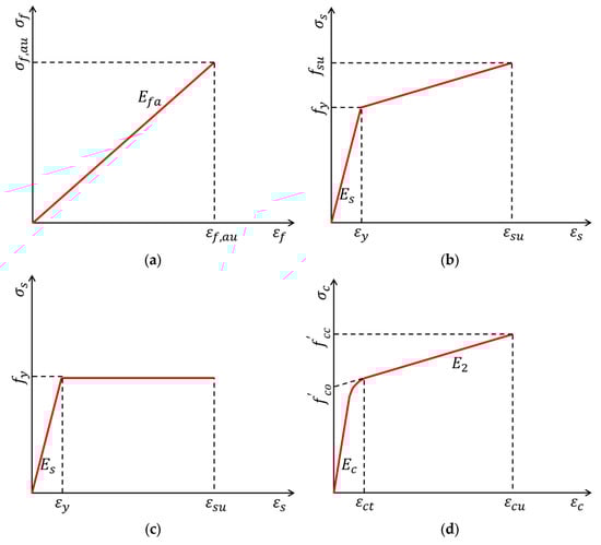
Figure 13.
Stress–strain relationships for FRP tube, steel, and confined concrete. (a) FRP tube. (b) Steel (Model I). (c) Steel (Model II). (d) Confined concrete.
3.5. Flexural Behavior of FCSRC Beams
Studies on the flexural behavior of FCSRC beams have been rather limited. Up to date, only Zakaib and Fam [57] have investigated the flexural performance of circular concrete-filled GFRP tube-encased I-section steel beams via experimentation. A total of ten beam specimens, including steel and CFFT control specimens, was tested under four-point bending, with the key parameters being the beam diameter, the GFRP tube thickness, and the laminate structure of the GFRP tube. It was revealed that the FCSRC beams with fiber angles of [−84/+6] had considerable increases in flexural strength, stiffness, and pseudo-ductility, which was attributed to the presence of the I-section steel. However, for FCSRC beams with fiber angles of [+54/−56], ductility was not improved by the presence of I-section steel because the CFFTs with fiber angles of [+54/−56] inherently possessed a ductile response. In addition, they addressed a moment connection through five cantilever bending tests (Figure 14) in which the embedded I-section steel was welded to a steel base plate, and they proposed a model to predict the moment capacity of the connection. They found that the strength and ductility of this connection primarily depended on the depth of the steel section embedded in the CFFT member. The minimum embedded lengths of the steel section required to reach the flexural strength of the CFFT member and the full plastic capacity of the moment connection at the fixed end were 17% and 48% of the CFFT span, respectively.
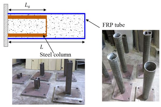
Figure 14.
Specimens in cantilever bending tests (reproduced with permission from ref. [57], copyright American Society of Civil Engineers 2012).
4. Application in Buckling Restrained Braces (BRBs)
Recently, FRP composites with high stiffness have been adopted to prevent the local and overall buckling failure of slender steel members [58,96,97,98]. Many efforts have been made to apply the concept of FCSRC systems in BRBs for structural repairing [58,59,60,61,62,63,64,65,66,67,68]. As shown in Table 2, previous studies on FCSRC BRBs have focused on behavior under axial compression or reversed cyclic loading. The studied parameters included variables of the constituent materials and the bond properties between them. Although the filling materials varied from study to study, BRBs can be divided into two categories: pre-fabricated BRBs and assembled BRBs. The former are usually made of pultruded FRP tubes, and the latter are made of FRP wraps. To this end, this section reviews the latest innovative research of FCSRC BRBs from these two aspects.
4.1. Pre-Fabricated BRBs
MacEachern and Sadeghian [62] tested 27 hybrid BRBs with a hot-rolled rectangular steel bar as core, self-consolidating grout as fillers and external GFRP tubes. They found that the hybrid BRBs could be designed to change the failure modes of the steel core from a sudden buckling failure to a ductile yielding when sized correctly. A typical load–stroke curve is presented in Figure 15, in which the response is divided into three segments: (i) Point i is the first peak load corresponding to the yielding (or bulking) of the steel core; (ii) point ii is the point at which the loading platen begins to contact the entire section and the grout carries the load; and (iii) point iii is the ultimate failure load corresponding to the overall system buckling or FRP shell rupture. They also revealed that increasing grout strength did not significantly improve the flexural rigidity for BRBs with smaller diameters, and the influence of the number of FRP confining layers on the overall flexural rigidity of the system was relatively small, especially for BRBs with larger diameters.
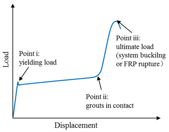
Figure 15.
Typical load–displacement curve of BRBs (adapted from MacEachern and Sadeghian [62]).
Similarly, Feng et al. [58] demonstrated the feasibility of FRP strengthening technique on BRBs via experimentation on L-shaped steel members with a certain slenderness, filled with bamboo splits or high-strength, non-shrinkage grout and externally confined with pultruded GFRP tubes. Subsequently, Feng et al. [59] conducted more thorough research on BRBs with mortar-filled pultruded GFRP tubes with different bi-axial symmetrical cross sections (cross/I/round/square) by experimental and theoretical modelling. It was concluded that the use of more FRP fabric in the middle of the brace (more than two layers) was redundant because it contributed little to the load carrying capacity and ductility, which was consistent with the findings of MacEachern and Sadeghian [62]. Three typical failure modes of strengthened specimens at peak load were also summarized in the study of Feng et al. [59].
Feng et al. [61] built finite element analysis (FEA) models to continually study more parameters (yield and ultimate strength of the steel, un-strengthened steel member length, interfacial bond, and initial imperfection) that affect the compressive behavior of BRBs with mortar-filled FRP tubes under axial compression. It was revealed that the ultimate load capacity of BRBs could increase with increases in the yield and ultimate strength of the steel and the bond strength of interface but decrease with increases in un-strengthened steel member length and initial imperfection.
Several studies have focused on the cyclic performance of BRBs. Sun et al. [63] investigated the hysteretic behavior of the pre-fabricated BRBs by testing seven BRB specimens with concrete-filled GFRP tubes and three BRB specimens with concrete-filled steel tubes. They found that global buckling only occurred in the medium- and long-length BRBs confined with filament-wound GFRP tubes (fibers in the hoop direction with a winding angle of 56°), while BRBs confined with pultruded GFRP tubes (fibers in both hoop and longitudinal directions) exhibited more stable hysteretic responses in which the maximum compressive loads could exceed about and no global buckling occurred. Thus, Sun et al. [63] suggested the use of filament-wound GFRP tubes for shorter BRB and pultruded GFRP tubes for longer BRBs.
4.2. Assembled BRBs
Assembled BRBs usually involve FRP wraps. They can be assembled or disassembled by wrapping or cutting the external FRP wraps, respectively, making repair or inspection easier. Research related to this form of BRBs has been extensively carried out [64,65,66,67,68]. Ekiz and El-Tawil [64] conducted an experimental and computational study to investigate the monotonic compressive behavior of small-scale BRBs with mortar or polyvinyl chloride (PVC) blocks as filling material and externally bonded CFRP sheets in the longitudinal and transverse directions (Figure 16a). Assembled BRBs are susceptible to stress concentration, so increasing the number of longitudinal CFRP layers can effectively prevent the premature rupture of the FRP wrap and improve the load-carrying capacity of the BRBs. Moreover, Ekiz and El-Taiwil [64] studied the effects of bonds. They demonstrated that the presence of the bond between the steel plate and the filling materials had an adverse effect on compressive ductility, as overall buckling appeared to occur earlier, but it was beneficial to inhibit the premature buckling of the FRP wrap.
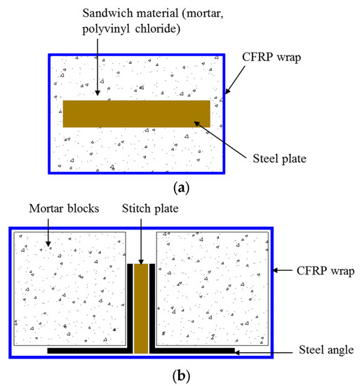

Figure 16.
Assembled BRB wrapped by FRPs. (a) Ekiz and El-Tawil [64]. (b) El-Tawil and Ekiz [65]. (c) Jia et al. [67]. (d) Deng et al. [66]. (e) Bashiri and Toufigh [68].
The cyclic behavior of assembled BRBs with FRP wrapping has attracted the attention of some researchers. El-Taiwil and Ekiz [65], Deng et al. [66], and Jia et al. [67] carried out reversed cyclic axial loading tests on different configurations of large-scale assembled BRBs. As shown in Figure 16b, El-Taiwil and Ekiz [65] proposed a new strengthening technique in which a core composed of pre-fabricated mortar blocks was attached to double steel angle sections and the entire system was wrapped with CFRP sheets in the longitudinal (main direction) and transverse fibers directions. They found that buckling restrained response could reach up to 2% inter-story drift. In the study of Jia et al. [67], the proposed BRBs comprised three components: a steel core plate, a pair of concrete-filled channel steel, and wrapped FRP clothes (Figure 16c). In addition, Deng et al. [66] designed a novel hybrid BRB in which four GFRP-pultruded tubes were tied to the core steel brace and cruciform cross section together and externally wrapped with GFRP layers (Figure 16d). On the other hand, Bashiri and Toufigh [68] utilized FRP partial wrapping strengthening schemes in BRBs. In their study, a pair of BRBs with a dog-bone-shaped steel core restrained with RC panels and wrapped with CFRP strips (Figure 16e) was placed into a half-scale steel frame, and the frame was tested under cyclic loading to assess the cyclic behavior of the proposed BRBs. It was demonstrated that the partial confinement of CFRP strips could provide adequate strength and stiffness for the BRBs to prevent buckling of the steel core.
5. Conclusions
Previous studies have indicated that FCSRC structural members are promising. This paper has presented a state-of-the-art review of FCSRC structural members in strengthening existing structures/constructing new structures and buckling restrained braces. Based on the literature review, several key conclusions can be drawn:
- (1)
- Using FRP confining devices and filling materials (the concept of FCSRC systems) to strengthen existing (corroded and buckled) steel columns is feasible: the load-carrying capacity of reinforced steel columns can be restored or even significantly increased to some extent due to the dual restraint of concrete and FRP tubes. In this case, in addition to the FRP-wrapping-based wet layup process, the split-tube construction process is also recommended.
- (2)
- FCSRCs have been developed into significant structural elements in new structures (e.g., hybrid columns or beams). The FRP confinement and composite action between the three components (i.e., steel, concrete, and FRP) generally result in the superior structural performance of FCSRC structural members.
- (3)
- Previous studies have primarily focused on the behavior of circular, square, and rectangular FCSRC columns subjected to concentric or eccentric compression. The investigated parameters included the cross-sectional shapes, the strength grades of the steel or the concrete, the slenderness ratio, and the load eccentricity.
- (4)
- In most cases, the buckling of inner steel section (especially overall buckling) can be effectively delayed or prevented by the surrounding concrete and the external FRP confining tube no matter its configuration, so the post-yield strength of steel can be fully exploited, further indicating the validation of the FCSRC system.
- (5)
- In addition to the FRP full wrapping strengthening, FRP partial wrapping strengthening has been used in FCSRC columns, and relevant research has indicated the feasibility of using FRP strips to confine concrete-encased steel columns.
- (6)
- New types of materials have been adopted in FCSRC columns. For instance, PET FCSRC columns exhibit much better deformation capacity than FCSRC columns made of conventional FRPs. PET FCSRC columns can fully exploit the strength of high-strength materials including high-strength steel and high-strength concrete.
- (7)
- Pre-stress could eliminate stress lag, and the strength of expansive concrete-based FCSRC columns is higher than that of FCSRC columns with ordinary concrete.
- (8)
- A number of models have been proposed for the load capacity and ultimate axial strain of FCSRC columns. These models are classified into three types based on the estimation of the contributions of three different components in FCSRC columns (i.e., FRP, concrete, and steel). However, these models have never considered the additional confinement from the steel section. The accuracy of these models also requires further evaluation.
- (9)
- Currently, research on FCSRC beams is rather limited. A previous study indicated the excellent flexural performance of FCSRC beams.
- (10)
- The concept of FCSRC systems has been applied to buckling restrained braces. Previous studies on FCSRC BRBs have focused on behavior under the axial compression or reversed cyclic loading, and they have demonstrated the feasibility of FRP strengthening technique for BRBs.
6. Future Opportunities
In order to facilitate the wide application of FCSRC systems in structural applications, it is necessary to gain an in-depth understanding of the structural performance of FCSRC systems subjected to various forms of loading. The gaps in knowledge and future research opportunities on FCSRC systems are identified and discussed below:
- (1)
- The effects of full and partial encasement of steel sections in surrounding concrete need to be explored.
- (2)
- The long-term structural performance of FCSRC structural members under extreme conditions (e.g., seismic, blast, impact, and aggressive environmental attacks) needs to be further explored.
- (3)
- Future efforts can focus on the development of FCSRC structural members made of high-performance materials.
- (4)
- The buckling behavior of steel sections may counteract the strength enhancement caused by their confinement; however, most models still assume that the steel is an idealized elastic–perfectly plastic material. Thus, it requires further investigation regarding the two aspects, and respective design standards need to be established.
- (5)
- Research on FCSRC beams is rather limited. The fatigue performance of FCSRC beams needs to be explored.
- (6)
- The bond behavior between the steel section and concrete in an FCSRC member needs to be understood. The combined use of bolt connections can result in full composite action. The interfacial bond between FRP and the concrete could be enhanced by using a proper device (such as a rough surface of the FRP with resin ribs or sand-coating).
- (7)
- The fire resistance of exterior FRP coatings is very important when FCSRC structural members are used in residential premises. It is necessary to adopt an effective approach (such as a fire-redundant coatings, as per GB 50608 [99]) to improve the fire performance of FRP materials.
- (8)
- It is necessary to develop new types of FCSRC BRBs that are more efficient and inexpensive.
- (9)
- FCSRCs are generally used as columns, beams, and buckling restrained braces in high-rise buildings or infrastructures. FCSRCs have been less used in spatial structures to date, which deserves further investigation.
- (10)
- Future work should address the issue of FRP layer protection against mechanical damage.
Author Contributions
Y.-Y.Y.: Investigation, Data curation, Roles/Writing—original draft; J.-J.Z.: Conceptualization, Funding acquisition, Supervision, Writing—review and editing; P.-L.L.: Writing—review and editing. All authors have read and agreed to the published version of the manuscript.
Funding
The authors acknowledge the financial support received from the National Natural Science Foundation of China (Nos. 51908137, 52178277), the Guangzhou Science and Technology Department (No. 201904010163), the Natural Science Foundation of Guangdong Province (No. 2021B1515020029).
Institutional Review Board Statement
Not applicable.
Informed Consent Statement
Not applicable.
Data Availability Statement
The data presented in this study are available on request from the corresponding author.
Conflicts of Interest
The authors declare no conflict of interest.
References
- Song, J.; Gao, W.-Y.; Ouyang, L.-J.; Zeng, J.-J.; Yang, J.; Liu, W.-D. Compressive behavior of heat-damaged square concrete prisms confined with basalt fiber-reinforced polymer jackets. Eng. Struct. 2021, 242, 112504. [Google Scholar] [CrossRef]
- Benmokrane, B.; Elgabbas, F.; Ahmed, E.A.; Cousin, P. Characterization and Comparative Durability Study of Glass/Vinylester, Basalt/Vinylester, and Basalt/Epoxy FRP Bars. J. Compos. Constr. 2015, 19, 04015008. [Google Scholar] [CrossRef]
- Lai, M.; Liang, Y.; Wang, Q.; Ren, F.; Chen, M.; Ho, J. A stress-path dependent stress-strain model for FRP-confined concrete. Eng. Struct. 2020, 203, 109824. [Google Scholar] [CrossRef]
- Raza, A.; Manalo, A.C.; Rafique, U.; AlAjarmeh, O.S. Concentrically loaded recycled aggregate geopolymer concrete columns reinforced with GFRP bars and spirals. Compos. Struct. 2021, 268, 113968. [Google Scholar] [CrossRef]
- Hadi, M.N.S.; Hasan, H.A.; Sheikh, M.N. Experimental Investigation of Circular High-Strength Concrete Columns Reinforced with Glass Fiber-Reinforced Polymer Bars and Helices under Different Loading Conditions. J. Compos. Constr. 2017, 21, 04017005. [Google Scholar] [CrossRef]
- Pan, B.Z.; Liu, F.; Zhuge, Y.; Zeng, J.-J.; Liao, J.J. ECC/UHPFRCC with and without FRP reinforcement for structural strengthening/repairing: A state-of-the-art review. Constr. Build. Mater. 2022, 316, 125824. [Google Scholar] [CrossRef]
- Zeng, J.-J.; Lin, G.; Teng, J.-G.; Li, L.-J. Behavior of large-scale FRP-confined rectangular RC columns under axial compression. Eng. Struct. 2018, 174, 629–645. [Google Scholar] [CrossRef]
- Ye, Y.Y.; Smith, S.T.; Zeng, J.J.; Zhuge, Y.; Quach, W.M. Novel ultra-high-performance concrete composite plates reinforced with FRP grid: Development and mechanical behavior. Compos. Struct. 2021, 269, 114033. [Google Scholar] [CrossRef]
- Zeng, J.-J.; Ye, Y.-Y.; Quach, W.-M.; Lin, G.; Zhuge, Y.; Zhou, J.-K. Compressive and transverse shear behaviour of novel FRP-UHPC hybrid bars. Compos. Struct. 2022, 281, 115001. [Google Scholar] [CrossRef]
- Ye, Y.-Y.; Liang, S.-D.; Feng, P.; Zeng, J.-J. Recyclable LRS FRP composites for engineering structures: Current status and future opportunities. Compos. Part B Eng. 2021, 212, 108689. [Google Scholar] [CrossRef]
- Liao, J.; Zeng, J.J.; Bai, Y.L.; Zhang, L. Bond strength of GFRP Bars to high strength and ultra-high strength fiber reinforced seawater sea-sand concrete (SSC). Compos. Struct. 2022, 281, 115013. [Google Scholar] [CrossRef]
- Ye, Y.-Y.; Zhuge, Y.; Smith, S.T.; Zeng, J.-J.; Bai, Y.-L. Behavior of GFRP-RC columns under axial compression: Assessment of existing models and a new axial load-strain model. J. Build. Eng. 2022, 47, 103782. [Google Scholar] [CrossRef]
- Zhou, J.-K.; Lin, W.-K.; Guo, S.-X.; Zeng, J.-J.; Bai, Y.-L. Behavior of FRP-confined FRP spiral reinforced concrete square columns (FCFRCs) under axial compression. J. Build. Eng. 2022, 45, 103452. [Google Scholar] [CrossRef]
- Liao, J.; Yang, K.Y.; Zeng, J.J.; Quach, W.M.; Ye, Y.Y.; Zhang, L. Compressive behavior of FRP-confined ultra-high performance concrete (UHPC) in circular columns. Eng. Struct. 2021, 249, 113246. [Google Scholar] [CrossRef]
- Zeng, J.-J.; Ye, Y.-Y.; Gao, W.-Y.; Smith, S.T.; Guo, Y.-C. Stress-strain behavior of polyethylene terephthalate fiber-reinforced polymer-confined normal-, high- and ultra high-strength concrete. J. Build. Eng. 2020, 30, 101243. [Google Scholar] [CrossRef]
- Teng, J.G.; Yu, T.; Wong, Y.L.; Dong, S.L. Hybrid FRP-concrete-steel tubular columns: Concept and behavior. Constr. Build. Mater. 2007, 21, 846–854. [Google Scholar] [CrossRef]
- Cheng, S.; Feng, P.; Bai, Y.; Ye, L.P. Load-Strain Model for Steel-Concrete-FRP-Concrete Columns in Axial Compression. J. Compos. Constr. 2016, 20, 04016017. [Google Scholar] [CrossRef]
- Xiong, Z.; Cai, Q.; Liu, F.; Li, L.; Long, Y. Dynamic performance of RAC-filled double-skin tubular columns subjected to cyclic axial compression. Constr. Build. Mater. 2020, 248, 118665. [Google Scholar] [CrossRef]
- Zhang, B.; Feng, G.-S.; Wang, Y.-L.; Lai, C.-C.; Wang, C.-C.; Hu, X.-M. Elliptical FRP-concrete-steel double-skin tubular columns under monotonic axial compression. Adv. Polym. Technol. 2020, 12, 1–16. [Google Scholar] [CrossRef]
- Yu, T.; Zhang, S.-S.; Huang, L.; Chan, C.-W. Compressive behavior of hybrid double-skin tubular columns with a large rupture strain FRP tube. Compos. Struct. 2017, 171, 10–18. [Google Scholar] [CrossRef]
- Zeng, J.-J.; Ye, Y.-Y.; Guo, Y.-C.; Lv, J.-F.; Ouyang, Y.; Jiang, C. PET FRP-concrete-high strength steel hybrid solid columns with strain-hardening and ductile performance: Cyclic axial compressive behavior. Compos. Part B Eng. 2020, 190, 107903. [Google Scholar] [CrossRef]
- Guo, Y.-C.; Ye, Y.-Y.; Lin, G.; Lv, J.-F.; Bai, Y.-L.; Zeng, J.-J. Effective usage of high strength steel tubes: Axial compressive behavior of hybrid FRP-concrete-steel solid columns. Thin-Walled Struct. 2020, 154, 106796. [Google Scholar] [CrossRef]
- Ye, Y.-Y.; Zhu, D.-H.; Zeng, J.-J.; Lin, G.; Wang, W. Rectangular double-tube concrete columns with an internal elliptical high-strength steel tube: Concept and behavior. Eng. Struct. 2020, 216, 110742. [Google Scholar] [CrossRef]
- Zeng, J.J.; Lv, J.F.; Lin, G.; Guo, Y.C.; Li, L.J. Compressive behavior of double-tube solid columns with an outer square FRP tube and an inner circular high strength steel tube. Constr. Build. Mater. 2018, 184, 668–680. [Google Scholar] [CrossRef]
- Zhao, H.C.; Ye, Y.Y.; Zeng, J.J.; Zhou, J.K.; Ouyang, Y. Axial compression tests on recycled polyethylene terephthalate fiber-reinforced polymer-confined concrete encased high strength steel tube hybrid square columns. Structures 2020, 28, 577–588. [Google Scholar] [CrossRef]
- Teng, J.-G.; Wang, Z.; Yu, T.; Zhao, Y.; Li, L.-J. Double-tube concrete columns with a high-strength internal steel tube: Concept and behaviour under axial compression. Adv. Struct. Eng. 2018, 21, 1585–1594. [Google Scholar] [CrossRef]
- Ozbakkaloglu, T. A novel FRP-dual-grade concrete-steel Hybrid column system. Thin-Walled Struct. 2015, 96, 295–306. [Google Scholar] [CrossRef]
- Guo, Y.C.; Xiao, S.H.; Shi, S.W.; Zeng, J.J.; Wang, W.Q.; Zhao, H.C. Axial compressive behavior of concrete-filled FRP-steel wire reinforced thermoplastics pipe hybrid columns. Compos. Struct. 2020, 224, 112237. [Google Scholar] [CrossRef]
- Zeng, J.-J.; Zheng, Y.-Z.; Long, Y.-L. Axial compressive behavior of FRP-concrete-steel double skin tubular columns with a rib-stiffened Q690 steel tube and ultra-high strength concrete. Compos. Struct. 2021, 268, 113912. [Google Scholar] [CrossRef]
- Zhang, Y.; Wei, Y.; Bai, J.; Wu, G.; Dong, Z. A novel seawater and sea sand concrete filled FRP-carbon steel composite tube column: Concept and behaviour. Compos. Struct. 2020, 246, 112421. [Google Scholar] [CrossRef]
- Wang, W.; Wu, C.; Liu, Z.; An, K.; Zeng, J.-J. Experimental Investigation of the Hybrid FRP-UHPC-Steel Double-Skin Tubular Columns under Lateral Impact Loading. J. Compos. Constr. 2020, 24, 04020041. [Google Scholar] [CrossRef]
- Liu, X.; Nanni, A.; Silva, P.F. Rehabilitation of Compression Steel Members Using FRP Pipes Filled with Non-Expansive and Expansive Light-Weight Concrete. Adv. Struct. Eng. 2005, 8, 129–142. [Google Scholar] [CrossRef]
- Karimi, K.; Tait, M.; El-Dakhakhni, W. Experimental investigation of two FRP retrofit schemes for strengthening steel columns. In Proceedings of the 9th U.S. National and 10th Canadian Conference on Earthquake Engineering, Toronto, ON, Canada, 25–29 July 2010. [Google Scholar]
- Karimi, K.; El-Dakhakhni, W.W.; Tait, M.J. Performance enhancement of steel columns using concrete-filled composite jackets. J. Perform. Constr. Fac. 2011, 25, 189–201. [Google Scholar] [CrossRef]
- Karimi, K.; El-Dakhakhni, W.; Tait, M.J. Behavior of Slender Steel-Concrete Composite Columns Wrapped with FRP Jackets. J. Perform. Constr. Facil. 2012, 26, 590–599. [Google Scholar] [CrossRef]
- Linde, J.K.; Tait, M.J.; El Dakhakhni, W.W.; Razavi, S.N. FRP-Confined Concrete Composite Retrofit System for Structural Steel Columns. J. Compos. Constr. 2015, 19, 04014086. [Google Scholar] [CrossRef]
- Karimi, K.; Tait, M.J.; El-Dakhakhni, W. Testing and modeling of a novel FRP-encased steel–concrete composite column. Compos. Struct. 2011, 93, 1463–1473. [Google Scholar] [CrossRef]
- Karimi, K.; Tait, M.J.; El-Dakhakhni, W.W. Influence of slenderness on the behavior of a FRP-encased steel-concrete composite column. J. Compos. Constr. 2012, 16, 100–109. [Google Scholar] [CrossRef]
- Cao, Q.; Li, X.; Lin, Z.; Wu, Z. Compression behavior of expansive concrete-encased-steel filled square CFRP tubes. Compos. Struct. 2019, 225, 111106. [Google Scholar] [CrossRef]
- Cao, Q.; Lv, X.; Li, X.; Gao, R.; Ma, Z.J. Effect of self-stressing on concrete-encased-steel filled circular CFRP tubes under axial compression. Structures 2021, 29, 471–483. [Google Scholar] [CrossRef]
- Chen, G.; Lan, Z.; Xiong, M.; Xu, Z. Compressive behavior of FRP-confined steel-reinforced high strength concrete columns. Eng. Struct. 2020, 220, 110990. [Google Scholar] [CrossRef]
- Huang, L.; Yu, T.; Zhang, S.-S.; Wang, Z.-Y. FRP-confined concrete-encased cross-shaped steel columns: Concept and behaviour. Eng. Struct. 2017, 152, 348–358. [Google Scholar] [CrossRef]
- Huang, L.; Zhang, S.; Yu, T.; Wang, Z. Compressive behaviour of large rupture strain FRP-confined concrete-encased steel columns. Constr. Build. Mater. 2018, 183, 513–522. [Google Scholar] [CrossRef]
- Huang, L.; Yu, T.; Wang, Z.-Y.; Zhang, S.-S. Compressive behaviour of slender FRP-confined concrete-encased cross-shaped steel columns. Constr. Build. Mater. 2020, 258, 120356. [Google Scholar] [CrossRef]
- Huang, L.; Yu, T.; Zhang, S.-S. FRP-Confined concrete-encased cross-shaped steel columns: Effects of key parameters. Compos. Struct. 2021, 272, 114252. [Google Scholar] [CrossRef]
- Liang, J.; Zou, W.; Li, W.; Liu, D. Behaviour of CFRP strips confined partially encased concrete columns under axial compressive load. Compos. Struct. 2021, 275, 114468. [Google Scholar] [CrossRef]
- Ren, F.; Liang, Y.; Ho, J.; Lai, M. Behaviour of FRP tube-concrete-encased steel composite columns. Compos. Struct. 2020, 241, 112139. [Google Scholar] [CrossRef]
- Ren, F.; Wu, D.; Chen, G.; Xie, P.; Xiong, M.-X.; Liang, Y. Slender FRP-confined steel-reinforced RAC columns under eccentric compression: Buckling behavior and design calculation models. Eng. Struct. 2021, 246, 113059. [Google Scholar] [CrossRef]
- Xiong, M.; Xu, Z.; Chen, G.; Lan, Z. FRP-confined steel-reinforced recycled aggregate concrete columns: Concept and behaviour under axial compression. Compos. Struct. 2020, 246, 112408. [Google Scholar] [CrossRef]
- Yu, T.; Lin, G.; Zhang, S.-S. Compressive behavior of FRP-confined concrete-encased steel columns. Compos. Struct. 2016, 154, 493–506. [Google Scholar] [CrossRef]
- Yu, T.; Teh, L.H.; Hadi, M.N.S. High-strength steel plates in hybrid fiber-reinforced polymer-concrete–steel columns: Concept and behavior. Adv. Struct. Eng. 2017, 20, 797–811. [Google Scholar] [CrossRef]
- Kaya, A.; Dawood, M.; Gencturk, B. Repair of corroded and buckled short steel columns using concrete-filled GFRP jackets. Constr. Build. Mater. 2015, 94, 20–27. [Google Scholar] [CrossRef]
- Ozbakkaloglu, T.; Fanggi, B.A.L. FRP-HSC-steel composite columns: Behavior under monotonic and cyclic axial compression. Mater. Struct. 2015, 48, 1075–1093. [Google Scholar] [CrossRef]
- He, K.; Chen, Y. Experimental evaluation of built-in channel steel concrete-filled GFRP tubular stub columns under axial compression. Compos. Struct. 2019, 219, 51–68. [Google Scholar] [CrossRef]
- Karagah, H.; Dawood, M.; Belarbi, A. Experimental Study of Full-Scale Corroded Steel Bridge Piles Repaired Underwater with Grout-Filled Fiber-Reinforced Polymer Jackets. J. Compos. Constr. 2018, 22, 04018008. [Google Scholar] [CrossRef]
- Xie, W.; Chen, Y.; Han, S.; Zhou, W.; He, K. Research on I steel reinforced concrete-filled GFRP tubular short columns. Thin-Walled Struct. 2017, 120, 282–296. [Google Scholar] [CrossRef]
- Zakaib, S.; Fam, A. Flexural Performance and Moment Connection of Concrete-Filled GFRP Tube–Encased Steel I-Sections. J. Compos. Constr. 2012, 16, 604–613. [Google Scholar] [CrossRef]
- Feng, P.; Bekey, S.; Zhang, Y.-H.; Ye, L.-P.; Bai, Y. Experimental Study on Buckling Resistance Technique of Steel Members Strengthened Using FRP. Int. J. Struct. Stab. Dyn. 2012, 12, 153–178. [Google Scholar] [CrossRef]
- Feng, P.; Zhang, Y.; Bai, Y.; Ye, L. Strengthening of steel members in compression by mortar-filled FRP tubes. Thin-Walled Struct. 2013, 64, 1–12. [Google Scholar] [CrossRef]
- Feng, P.; Zhang, Y.; Hu, L.; Gong, D. Buckling of piecewise member composed of steel and high-strength materials in axial compression. Thin-Walled Struct. 2017, 110, 62–74. [Google Scholar] [CrossRef]
- Feng, P.; Hu, L.L.; Zhang, Y.H.; Ye, L.P. Behavior analysis of FRP tube/filling strengthened steel members under axial compression. Thin-Walled Struct. 2019, 134, 475–490. [Google Scholar] [CrossRef]
- MacEachern, D.; Sadeghian, P. Hybrid FRP Strengthening of Slender Steel Members for Buckling Control. J. Compos. Constr. 2020, 24, 04020039. [Google Scholar] [CrossRef]
- Sun, H.; Jia, M.; Zhang, S.; Wang, Y. Study of buckling-restrained braces with concrete infilled GFRP tubes. Thin-Walled Struct. 2019, 136, 16–33. [Google Scholar] [CrossRef]
- Ekiz, E.; El-Tawil, S. Restraining steel brace buckling using a carbon fiber-reinforced polymer composite system experiments and computational simulation. J. Compos. Constr. 2008, 12, 562–569. [Google Scholar] [CrossRef]
- El-Tawil, S.; Ekiz, E. Inhibiting Steel Brace Buckling Using Carbon Fiber-Reinforced Polymers: Large-Scale Tests. J. Struct. Eng. 2009, 135, 530–538. [Google Scholar] [CrossRef]
- Deng, K.; Pan, P.; Nie, X.; Xu, X.; Feng, P.; Ye, L. Study of GFRP Steel Buckling Restraint Braces. J. Compos. Constr. 2015, 19, 04015009. [Google Scholar] [CrossRef]
- Jia, M.; Yu, X.; Lu, D.; Lu, B. Experimental research of assembled buckling-restrained braces wrapped with carbon or basalt fiber. J. Constr. Steel Res. 2017, 131, 144–161. [Google Scholar] [CrossRef]
- Bashiri, M.; Toufigh, V. Numerical and experimental investigation on a BRB confined with partially carbon fiber reinforced polymer (CFRP). Eng. Struct. 2020, 223, 111150. [Google Scholar] [CrossRef]
- Ouyang, Y.; Kwan, A.K.H. Finite element analysis of square concrete-filled steel tube (CFST) columns under axial compressive load. Eng. Struct. 2018, 156, 443–459. [Google Scholar] [CrossRef]
- Han, L.-H.; He, S.-H.; Liao, F.-Y. Performance and calculations of concrete filled steel tubes (CFST) under axial tension. J. Constr. Steel Res. 2011, 67, 1699–1709. [Google Scholar] [CrossRef]
- Han, L.H.; Tao, Z.; Yao, G.H. Behaviour of concrete filled steel tubular members subjected to shear and constant axial compression. Thin-Walled Struct. 2008, 46, 765–780. [Google Scholar] [CrossRef]
- Tao, Z.; Han, L.-H.; Zhuang, J.-P. Axial Loading Behavior of CFRP Strengthened Concrete-Filled Steel Tubular Stub Columns. Adv. Struct. Eng. 2007, 10, 37–46. [Google Scholar] [CrossRef]
- Hu, Y.M.; Yu, T.; Teng, J.G. FRP-Confined Circular Concrete-Filled Thin Steel Tubes under Axial Compression. J. Compos. Constr. 2011, 15, 850–860. [Google Scholar] [CrossRef]
- Lu, Y.; Li, N.; Li, S. Behavior of FRP-Confined Concrete-Filled Steel Tube Columns. Polymers 2014, 6, 1333–1349. [Google Scholar] [CrossRef]
- Ostrowski, K.; Dudek, M.; Sadowski, Ł. Compressive behaviour of concrete-filled carbon fiber-reinforced polymer steel composite tube columns made of high performance concrete. Compos. Struct. 2019, 234, 111668. [Google Scholar] [CrossRef]
- Zeng, J.-J.; Zheng, Y.-W.; Liu, F.; Guo, Y.-C.; Hou, C. Behavior of FRP Ring-Confined CFST columns under axial compression. Compos. Struct. 2020, 257, 113166. [Google Scholar] [CrossRef]
- Young, B.; Ellobody, E. Performance of axially restrained concrete encased steel composite columns at elevated temperatures. Eng. Struct. 2011, 33, 245–254. [Google Scholar] [CrossRef]
- Lai, B.; Liew, J.R. Investigation on axial load-shorting behaviour of high strength concrete encased steel composite section. Eng. Struct. 2021, 227, 111401. [Google Scholar] [CrossRef]
- Gautham, A.; Sahoo, D.R. Behavior of steel-reinforced composite concrete columns under combined axial and lateral cyclic loading. J. Build. Eng. 2021, 39, 102305. [Google Scholar] [CrossRef]
- Xue, Y.C.; Yang, Y.; Yu, Y.L. Pseudostatic testing for load-carrying capacity of precast concrete-encased steel composite columns. J. Build. Eng. 2020, 29, 101189. [Google Scholar] [CrossRef]
- Xiao, J.; Li, W.; Fan, Y.; Huang, X. An overview of study on recycled aggregate concrete in China (1996–2011). Constr. Build. Mater. 2012, 31, 364–383. [Google Scholar] [CrossRef]
- Kisku, N.; Joshi, H.; Ansari, M.; Panda, S.; Nayak, S.; Dutta, S. A critical review and assessment for usage of recycled aggregate as sustainable construction material. Constr. Build. Mater. 2017, 131, 721–740. [Google Scholar] [CrossRef]
- Poon, C.S.; Chan, D. The use of recycled aggregate in concrete in Hong Kong. Resour. Conserv. Recycl. 2007, 50, 293–305. [Google Scholar] [CrossRef]
- Zeng, J.-J.; Zhang, X.-W.; Chen, G.-M.; Wang, X.-M.; Jiang, T. FRP-confined recycled glass aggregate concrete: Concept and axial compressive behavior. J. Build. Eng. 2020, 30, 101288. [Google Scholar] [CrossRef]
- Silva, R.; de Brito, J.; Evangelista, L.; Dhir, R. Design of reinforced recycled aggregate concrete elements in conformity with Eurocode 2. Constr. Build. Mater. 2016, 105, 144–156. [Google Scholar] [CrossRef]
- Yang, Y.-F.; Hou, C. Behaviour and design calculations of recycled aggregate concrete-filled steel tube (RACFST) members. Mag. Concr. Res. 2015, 67, 611–620. [Google Scholar] [CrossRef]
- Mortazavi, A.A.; Pilakoutas, K.; Son, K.S. RC column strengthening by lateral pre-tensioning of FRP. Constr. Build. Mater. 2003, 17, 491–497. [Google Scholar] [CrossRef]
- Cao, Q.; Tao, J.; John, Z.; Wu, Z. Axial Compressive Behavior of CFRP-Confined Expansive Concrete Columns. ACI Struct. J. 2017, 114, 475–485. [Google Scholar] [CrossRef][Green Version]
- Vincent, T.; Ozbakkaloglu, T. Compressive Behavior of Prestressed High-Strength Concrete-Filled Aramid FRP Tube Columns: Experimental Observations. J. Compos. Constr. 2015, 19, 04015003. [Google Scholar] [CrossRef]
- Karimi, K.; Tait, M.J.; El-Dakhakhni, W.W. Analytical modeling and axial load design of a novel FRP-encased steel–concrete composite column for various slenderness ratios. Eng. Struct. 2013, 46, 526–534. [Google Scholar] [CrossRef]
- EN 1994-1-1; Eurocode 4: Design of Composite Steel and Concrete Structures—Part 1-1: General Rules and Rules for Buildings. European Committee for Standardization: Brussels, Belgium, 2004.
- Teng, J.G.; Jiang, T.; Lam, L.; Luo, Y.Z. Refinement of a Design-Oriented Stress–Strain Model for FRP-Confined Concrete. J. Compos. Constr. 2009, 13, 269–278. [Google Scholar] [CrossRef]
- Lam, L.; Teng, J. Design-oriented stress–strain model for FRP-confined concrete. Constr. Build. Mater. 2003, 17, 471–489. [Google Scholar] [CrossRef]
- Attard, M.M.; Setunge, S. Stress-strain relationship of confined and unconfined concrete. Mater. J. 1996, 93, 432–442. [Google Scholar]
- GB50017-2017; Code for Design of Steel Structures. China Planning Press: Beijing, China, 2003.
- Jones, S.C.; Civjan, S.A. Application of Fiber Reinforced Polymer Overlays to Extend Steel Fatigue Life. J. Compos. Constr. 2003, 7, 331–338. [Google Scholar] [CrossRef]
- Shaat, A.; Fam, A. Slender Steel Columns Strengthened Using High-Modulus CFRP Plates for Buckling Control. J. Compos. Constr. 2009, 13, 2–12. [Google Scholar] [CrossRef]
- Bhetwal, K.K.; Yamada, S. Effects of Cfrp Reinforcements on the Buckling Behavior of Thin-Walled Steel Cylinders Under Compression. Int. J. Struct. Stab. Dyn. 2012, 12, 131–151. [Google Scholar] [CrossRef]
- GB-50608; Technical Code for Infrastructure Application of FRP Composites. China Architecture and Building Press: Beijing, China, 2010.


Publisher’s Note: MDPI stays neutral with regard to jurisdictional claims in published maps and institutional affiliations. |
© 2022 by the authors. Licensee MDPI, Basel, Switzerland. This article is an open access article distributed under the terms and conditions of the Creative Commons Attribution (CC BY) license (https://creativecommons.org/licenses/by/4.0/).