
Experimental Findings and Validation on Torsional Behaviour of Fibre-Reinforced Concrete Beams: A Review

 , ,
, ,  , ,
, , 
Abstract
:1. Introduction
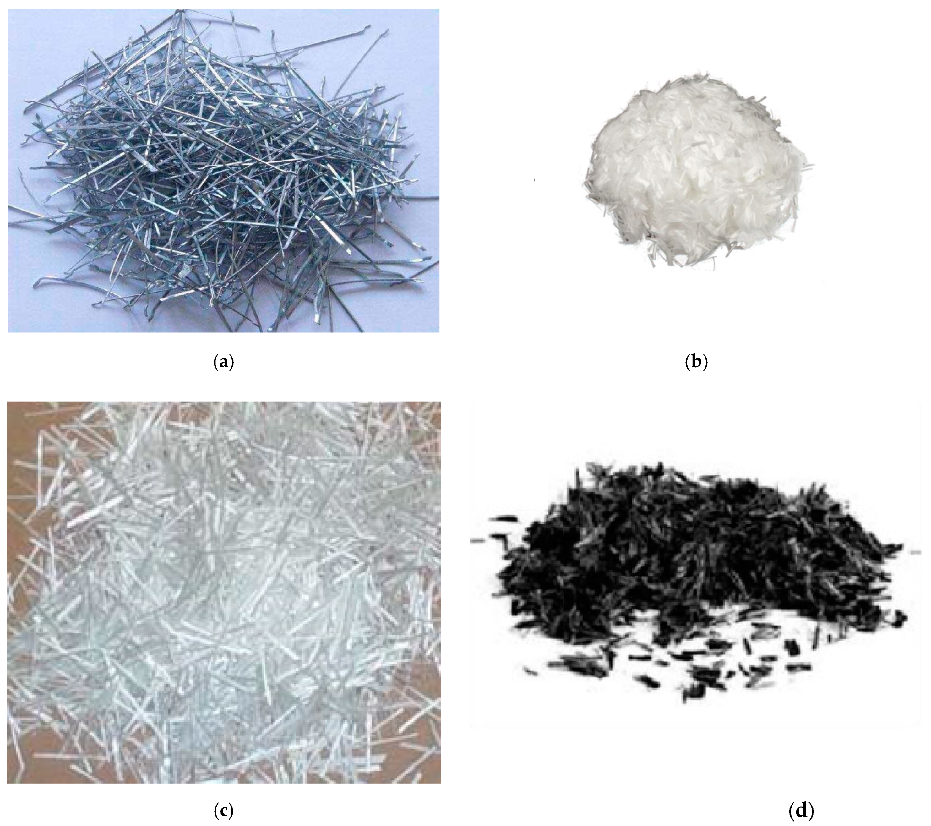
2. Types of Fibre Reinforced Concrete
- Reinforced Concrete incorporating steel fibres
- Reinforced Concrete incorporating synthetic fibres
- Reinforced Concrete incorporating hybrid fibres
2.1. Reinforced Concrete Incorporating Steel Fibres
2.2. Reinforced Concrete Incorporating Synthetic Fibres
2.2.1. Polypropylene Fibre Reinforced (PFR) Cement Mortar and Concrete
2.2.2. Glass Fibre Reinforced Concrete
2.2.3. Carbon Fibre Reinforced Concrete
2.2.4. Asbestos Fibre Reinforced Concrete
2.2.5. Organic Fibre Reinforced Concrete
2.3. Reinforced Concrete Incorporating Hybrid Fibres
3. Types of Fibre Reinforced Polymers
- Carbon fibre reinforced polymers (CFRP)
- Glass fibre reinforced polymers (GFRP)
- Aramid fibre reinforced polymers (AFRP)
- Natural fibre reinforced polymers (NFRP)
3.1. Carbon Fibre Reinforced Polymers (CFRP)
3.2. Glass Fibre Reinforced Polymers (GFRP)
3.3. Aramid Fibre Reinforced Polymers (AFRP)
3.4. Natural Fibre Reinforced Polymers (NFRP)
4. Methods Adopted by Previous Studies
5. Results and Discussion
5.1. Steel Fibre Reinforced Concrete Findings
5.2. Synthetic Fibre Reinforced (SYF) Concrete
Polypropylene Fibre Reinforced (PFR) Cement Mortar and Concrete
5.3. Hybrid Fibre Reinforced Concrete
5.4. Fibre Reinforced Polymer Concrete
5.4.1. Glass Fibre Reinforced Polymer Concrete
5.4.2. Carbon Fibre Reinforced Polymer Concrete
5.4.3. Aramid Fibre Reinforced Polymer Concrete
6. Conclusions
- Fibre reinforced concrete requires special mixing conditions to mitigate fibre segregation, the balling effect, and the difficulty of consistently amalgamating the components. Increases in aspect ratio, volume fraction, and coarse aggregate quantity and size exacerbate the challenges and balling propensity. Steel fibres with a more than 2% composition in volume and ratio of the length to the diameter greater than 100 are difficult to blend. Fibres used for concrete production must be evenly distributed in the mixture; proper mixing may be accomplished through adding the fibres before the water. When using a laboratory mixer, delivering the fibres through a wire mesh sieve will aid in equal fibre dispersion.
- For effective stress transmission, the matrix of the coefficient of elasticity must be significantly less than that of the fibre. Low modulus fibres, such as nylon 66, polypropylene and acrylic, are less inclined to boost torsional capacity, but they can aid in the intake of huge amounts of energy and result in increased hardness and resilience. Steel, glass, and carbon fibres with a high modulus increase the strength and rigidity of the composite. The efficacy of stress transmission from the matrix to the fibre is also determined by the interfacial connection between the matrix and the fibre. A strong bond is required to increase concrete’s torsional strength.
- The orientation of fibres is also important for improving concrete’s torsional strength. The fibres were found to have high torsional strength and toughness when they were oriented consistently.
- To avoid a significant drop in composite strength, the coarse aggregate size should be limited to 10 mm. Fibres also serve as aggregates. Despite their basic shape, they have a complicated impact on the characteristics of the concrete mix. The fibre distribution and orientation and the features of the composite are controlled by an inter-particle interaction between fibres and aggregates. Friction-reducing admixtures and admixtures that increase the mix’s cohesion can make a big difference.
- The aspect ratio of the fibre is another crucial feature that determines the composite’s characteristics and behaviour. It has been discovered that increasing the aspect ratio up to 75 raises the ultimate strength of concrete linearly. Relative torsional strength and toughness decline in the region of 75.
Author Contributions
Funding
Institutional Review Board Statement
Informed Consent Statement
Acknowledgments
Conflicts of Interest
References
- Marvila, M.T.; Azevedo, A.R.G.; Cecchin, D.; Costa, J.M.; Xavier, G.C.; de Fátima do Carmo, D.; Monteiro, S.N. Durability of coating mortars containing açaí fibers. Case Stud. Constr. Mater. 2020, 13, e00406. [Google Scholar] [CrossRef]
- Martins, R.O.G.; Alvarenga, R.D.C.S.S.; Pedroti, L.G.; de Oliveira, A.F.; Mendes, B.C.; de Azevedo, A.R.G. Assessment of the durability of grout submitted to accelerated carbonation test. Constr. Build. Mater. 2018, 159, 261–268. [Google Scholar] [CrossRef]
- Kandekar, S.B.; Talikoti, R.S. Torsional behaviour of reinforced concrete beam wrapped with aramid fiber. J. King Saud Univ.-Eng. Sci. 2019, 31, 340–344. [Google Scholar] [CrossRef]
- Mane, V.V.; Patil, N.K. A review on “torsional behavior of rectangular reinforced concrete beams with encased welded wire mesh fiber”. Reliab. Theory Appl. 2021, 16, 304–317. [Google Scholar] [CrossRef]
- Prakash, R.; Thenmozhi, R.; Raman, S.N.; Subramanian, C. Fibre reinforced concrete containing waste coconut shell aggregate, fly ash and polypropylene fibre. Rev. Fac. Ing. Univ. Antioq. 2019, 94, 33–42. [Google Scholar] [CrossRef] [Green Version]
- Blazy, J.; Blazy, R. Polypropylene fiber reinforced concrete and its application in creating architectural forms of public spaces. Case Stud. Constr. Mater. 2021, 14, e00549. [Google Scholar] [CrossRef]
- Neuba, L.D.M.; Junio, R.F.P.; Ribeiro, M.P.; Souza, A.T.; Lima, E.D.S.; Filho, F.D.C.G.; Figueiredo, A.B.-H.D.S.; Braga, F.D.O.; De Azevedo, A.R.G.; Monteiro, S.N. Promising mechanical, thermal, and ballistic properties of novel epoxy composites reinforced with Cyperus malaccensis sedge fiber. Polymers 2020, 12, 1776. [Google Scholar] [CrossRef]
- Goud, E.P.K.; Praveen, K.S. Experimental comparative study on the mechanical properties of hooked end steel, crimped steel and glass fiber reinforced concrete. Int. J. Eng. Trends Technol. 2015, 21, 252–256. [Google Scholar] [CrossRef]
- Majumdar, A.J. Fibre cement and concrete—A review. Composites 1975, 6, 7–16. [Google Scholar] [CrossRef]
- de Azevedo, A.R.G.; Marvila, M.T.; Antunes, M.L.P.; Rangel, E.C.; Fediuk, R. Technological Perspective for Use the Natural Pineapple Fiber in Mortar to Repair Structures. Waste Biomass Valoriz. 2021, 12, 5131–5145. [Google Scholar] [CrossRef]
- Gornale, A.; Quadri, S.I.; Quadri, S.M.; Ali, S.M.A.; Hussaini, S.S. Strength Aspects of Glass Fibre Reinforced Concrete. Int. J. Sci. Eng. Res. 2012, 3, 3–7. [Google Scholar]
- Jacoby, M. Composite materials. In Chemical and Engineering News; Meyers, R.A.B.T.-E., Ed.; Academic Press: New York, NY, USA, 2004; Volume 82, pp. 34–39. ISBN 978-0-12-227410-7. [Google Scholar]
- Savino, V.; Lanzoni, L.; Tarantino, A.M.; Viviani, M. Simple and effective models to predict the compressive and tensile strength of HPFRC as the steel fiber content and type changes. Compos. Part B Eng. 2018, 137, 153–162. [Google Scholar] [CrossRef] [Green Version]
- Gao, D.; Wang, F. Effects of recycled fine aggregate and steel fiber on compressive and splitting tensile properties of concrete. J. Build. Eng. 2021, 44, 102631. [Google Scholar] [CrossRef]
- Arya, S.; Arun, H.J. An Experimental Investigation on Mechanical Properties of Concrete by Partially Replacing Cement with Silica Fume and Fly Ash. Int. J. Eng. Res. 2017, 6, 105–116. [Google Scholar] [CrossRef]
- Graf, O.; Mörsch, E. Verdrehungsversuche zur Klärung der Schubfestigkeit von Eisenbeton; Deutsche Nationalbibliothek: Berlin, Germany, 1922. [Google Scholar]
- Fang, I.K.; Shiau, J.K. Torsional behavior of normal- and high-strength concrete beams. ACI Struct. J. 2004, 101, 304–313. [Google Scholar] [CrossRef]
- Chalioris, C.E. Torsional strengthening of rectangular and flanged beams using carbon fibre-reinforced-polymers—Experimental study. Constr. Build. Mater. 2008, 22, 21–29. [Google Scholar] [CrossRef]
- Deifalla, A.; Ghobarah, A. Strengthening RC T-Beams Subjected to Combined Torsion and Shear Using FRP Fabrics: Experimental Study. J. Compos. Constr. 2010, 14, 301–311. [Google Scholar] [CrossRef]
- Carvalho, A.; Xavier, G.C.; Alexandre, J.; Pedroti, L.G.; de Azevedo, A.R.G.; Vieira, C.M.F.; Monteiro, S.N. Environmental durability of soil-cement block incorporated with ornamental stone waste. Mat. Sc. Forum. 2014, 25, 25–35. [Google Scholar] [CrossRef]
- Rausch, E. Berechnung des Eisenbetons gegen Verdrehung (Torsion) and Abscheren; Julius Springer-Verlag: Berlin, Germany, 1929; p. 51. [Google Scholar]
- Lampert, P.; Thürlimann, B. Ultimate Strength and Design of Reinforced Concrete Beams in Torsion and Bending. In Ultimate Strength and Design of Reinforced Concrete Beams in Torsion and Bending/Résistance et Dimensionnement des Poutres en Béton Armé Soumises à la Torsion Et à la Flexion/Bruchwiderstand und Bemessung von Stahlbetonbalken unter Torsion und Biegung; Birkhäuser: Basel, Switzerland, 1972; Volume 42, pp. 107–131. [Google Scholar]
- American Concrete Institute. Report on Torsion in Structural Concrete; American Concrete Institute: Indianapolis, IN, USA, 2015; Volume 28, ISBN 9780870318108. [Google Scholar]
- Park, R.; Paulay, T. Strength and Deformation of Members with Shear. Reinf. Concr. Struct. 1975, 1, 270–345. [Google Scholar] [CrossRef]
- Deifalla, A.F.; Zapris, A.G.; Chalioris, C.E. Multivariable Regression Strength Model for Steel Fiber-Reinforced Concrete Beams under Torsion. Materials 2021, 14, 3889. [Google Scholar] [CrossRef]
- Chkheiwer, A.H.; Ahmed, M.A.; Hassan, Z. Verification of a Torsional Behaviour Prediction Model for Reinforced Recycled Aggregate Concrete Beams. J. Eng. 2022, 2022, 3340489. [Google Scholar] [CrossRef]
- Leonhardt, F.; Mönnig, E. Lectures on Structural Engineering—Part I. Fundamentals in the Design of Reinforced Concrete Construction; Springer: Berlin, Germany, 1973. [Google Scholar]
- Holst, J.M.F.G.; Rotter, J.M.; Calladine, C.R.; Eoin, Dunphy; NORM, E.S.N.E.Euro.; DNV; Carvalho, E.C.; Sc, C.T.C.; Park, O.; Haftka, R.T.; et al. En1992-1-1. J. Constr. Steel Res. 2011, 54, 18–20. [Google Scholar]
- Li, V.C. On Engineered Cementitious Composites (ECC). J. Adv. Concr. Technol. 2003, 1, 215–230. [Google Scholar] [CrossRef] [Green Version]
- Susetyo, J.; Gauvreau, P.; Vecchio, F.J. Effectiveness of steel fiber as minimum shear reinforcement. ACI Struct. J. 2012, 109, 426–428. [Google Scholar]
- Minelli, F.; Plizzari, G.A. On the effectiveness of steel fibers as shear reinforcement. ACI Struct. J. 2013, 110, 379–389. [Google Scholar] [CrossRef]
- Facconi, L.; Minelli, F. Behavior of lightly reinforced fiber reinforced concrete panels under pure shear loading. Eng. Struct. 2020, 202, 109879. [Google Scholar] [CrossRef]
- Nipurte, O.; Patil, L.; Patil, P.; Potinda, V. Study of Behaviour of Steel Fiber Reinforced Concrete in Deep Beam for Flexure. Eng. Technol. 2018, 4, 1018–1025. [Google Scholar]
- Patil, S.P.; Sangle, K.K. Tests of steel fibre reinforced concrete beams under predominant torsion. J. Build. Eng. 2016, 6, 157–162. [Google Scholar] [CrossRef]
- Filho, J.J.H.S.; de Souza Sánchez Filho, E.; de Souza Lima Velasco, M. Torsion strengthening of RC beams with carbon fibre composites. Struct. Concr. 2010, 11, 181–190. [Google Scholar] [CrossRef]
- Facconi, L.; Minelli, F.; Ceresa, P.; Plizzari, G. Steel fibers for replacing minimum reinforcement in beams under torsion. Mater. Struct. Constr. 2021, 54, 34. [Google Scholar] [CrossRef]
- Amin, A.; Bentz, E.C. Strength of steel fiber reinforced concrete beams in pure torsion. Struct. Concr. 2018, 19, 684–694. [Google Scholar] [CrossRef]
- Zhou, J.; Shen, W.; Wang, S. Experimental study on torsional behavior of FRC and ECC beams reinforced with GFRP bars. Constr. Build. Mater. 2017, 152, 74–81. [Google Scholar] [CrossRef]
- Lau, C.K.; Htut, T.N.S.; Melling, J.J.; Chegenizadeh, A.; Ng, T.S. Torsional behaviour of steel fibre reinforced alkali activated concrete. Materials 2020, 13, 3423. [Google Scholar] [CrossRef]
- Chiaia, B.; Fantilli, A.P.; Vallini, P. Evaluation of crack width in FRC structures and application to tunnel linings. Mater. Struct. Constr. 2009, 42, 339–351. [Google Scholar] [CrossRef]
- Tiberti, G.; Minelli, F.; Plizzari, G. Reinforcement optimization of fiber reinforced concrete linings for conventional tunnels. Compos. Part B Eng. 2014, 58, 199–207. [Google Scholar] [CrossRef]
- De La Fuente, A.; Lin, L.; Cavalaro, S.; Aguado, A. Design of FRC tunnel segments considering the ductility requirements of the fib Model Code 2010: Application to the Barcelona Metro line 9. Am. Concr. Inst. ACI Spec. Publ. 2014, 2014, 471–480. [Google Scholar] [CrossRef]
- di Prisco, M.; Martinelli, P.; Parmentier, B. On the reliability of the design approach for FRC structures according to fib Model Code 2010: The case of elevated slabs. Struct. Concr. 2016, 17, 588–602. [Google Scholar] [CrossRef]
- Facconi, L.; Plizzari, G.; Minelli, F. Elevated slabs made of hybrid reinforced concrete: Proposal of a new design approach in flexure. Struct. Concr. 2019, 20, 52–67. [Google Scholar] [CrossRef] [Green Version]
- Paper, C.; Jain, A.; Group, R. Comparative Study on Strengthening of RC Beam in Flexure using CFRP & GFRP: A Review. Int. J. Sci. Technol. Eng. 2016, 2, 129–132. [Google Scholar]
- Mohammed, L.; Ansari, M.N.M.; Pua, G.; Jawaid, M.; Islam, M.S. A Review on Natural Fiber Reinforced Polymer Composite and Its Applications. Int. J. Polym. Sci. 2015, 2015, 243947. [Google Scholar] [CrossRef] [Green Version]
- Ferracuti, B.; Savoia, M.; Mazzotti, C. Interface law for FRP-concrete delamination. Compos. Struct. 2007, 80, 523–531. [Google Scholar] [CrossRef]
- Xue, W.; Zeng, L.; Tan, Y. Experimental studies on bond behaviour of high strength CFRP plates. Compos. Part B Eng. 2008, 39, 592–603. [Google Scholar] [CrossRef]
- Woo, S.K.; Nam, J.W.; Kim, J.H.J.; Han, S.H.; Byun, K.J. Suggestion of flexural capacity evaluation and prediction of prestressed CFRP strengthened design. Eng. Struct. 2008, 30, 3751–3763. [Google Scholar] [CrossRef]
- Barris, C.; Torres, L.; Turon, A.; Baena, M.; Catalan, A. An experimental study of the flexural behaviour of GFRP RC beams and comparison with prediction models. Compos. Struct. 2009, 91, 286–295. [Google Scholar] [CrossRef]
- Saikia, B.; Kumar, P.; Thomas, J.; Rao, K.S.N.; Ramaswamy, A. Strength and serviceability performance of beams reinforced with GFRP bars in flexure. Constr. Build. Mater. 2007, 21, 1709–1719. [Google Scholar] [CrossRef]
- He, J.; Liu, Y.; Chen, A.; Dai, L. Experimental investigation of movable hybrid GFRP and concrete bridge deck. Constr. Build. Mater. 2012, 26, 49–64. [Google Scholar] [CrossRef]
- Monteiro, S.N.; Satyanarayana, K.G.; Ferreira, A.S.; Nascimento, D.C.O.; Lopes, F.P.D.; Silva, I.L.A.; Bevitori, A.B.; Inácio, W.P.; Neto, J.B.; Portela, T.G. Selection of high strength natural fibers. Rev. Mater. 2010, 15, 488–505. [Google Scholar] [CrossRef]
- Dittenber, D.B.; Gangarao, H.V.S. Critical review of recent publications on use of natural composites in infrastructure. Compos. Part A Appl. Sci. Manuf. 2012, 43, 1419–1429. [Google Scholar] [CrossRef]
- Nwankwo, C.O.; Ede, A.N. Flexural strengthening of reinforced concrete beam using a natural fibre reinforced polymer laminate: An experimental and numerical study. Mater. Struct. Constr. 2020, 53, 142. [Google Scholar] [CrossRef]
- George, A.; Sofi, A. Torsional and cracking behaviours of normal weight and coconut shell lightweight concretes. J. Eng. Sci. Technol. 2018, 13, 4104–4117. [Google Scholar]
- Usman, F.; Shaharudin, M.S. Effect of Polypropylene Fibres on Torsional Strength of Ferrocement. Indian J. Sci. Technol. 2018, 11, 1–5. [Google Scholar] [CrossRef] [Green Version]
- Saravanakumar, P.; Sivakamidevi, M.; Meena, K.; Yamini, S.P. An experimental study on hybrid fiber reinforced concrete beams subjected to torsion. Mater. Today Proc. 2021, 45, 6818–6821. [Google Scholar] [CrossRef]
- Hassan, R.F.; Jaber, M.H.; Al-Salim, N.H.; Hussein, H.H. Experimental research on torsional strength of synthetic/steel fiber-reinforced hollow concrete beam. Eng. Struct. 2020, 220, 110948. [Google Scholar] [CrossRef]
- Tudu, C. Study of Torsional Behaviour of Rectangular Reinforced Concrete Beams. Master’s Thesis, National Institute of Technology Rourkela, Rourkela, India, 2012. Volume 2. [Google Scholar]
- Tibhe, S.B.; Rathi, V.R. Comparative Experimental Study on Torsional Behavior of RC Beam Using CFRP and GFRP Fabric Wrapping. Procedia Technol. 2016, 24, 140–147. [Google Scholar] [CrossRef] [Green Version]
- Chalioris, C.E. Tests and analysis of reinforced concrete beams under torsion retrofitted with FRP strips. WIT Trans. Model. Simul. 2007, 46, 633–642. [Google Scholar] [CrossRef] [Green Version]


| References | Specimens | Beam Length | Beam Width | Beam Depth | Fibre Type | Aspect Ratio | Specific Gravity | Supplied Steel Dosage | Area of Steel at Bottom | Area of Steel at Top | Area of Steel for Shear Links | Cu, Concrete (N/mm2) | Type of Cement | W/C | Mix Proportion | Size of Coarse Agreggates | Admixtures |
|---|---|---|---|---|---|---|---|---|---|---|---|---|---|---|---|---|---|
| Amin and Bentz [37] | T-0-8 | 1600 | 200 | 280 | 603.000 | 157.000 | 251.000 | 42.300 | |||||||||
| T-0-10 | 603.000 | 157.000 | 393.000 | 42.300 | |||||||||||||
| T-30-8 | Steel (RC-65/35-BN cold drawn wire fibers 1345 MPa) | 54.5 | 31.200 | 0.38 | 603.000 | 157.000 | 251.000 | 42.300 | |||||||||
| T-0-10 | 54.5 | 31.200 | 0.38 | 603.000 | 157.000 | 393.000 | 42.300 | ||||||||||
| Facconi et al. [20] | TB1-PC | 2700 | 300 | 300 | 509.000 | 509.000 | 31.700 | CEM I 42.5R | 0.5 | 1:2.84:1.95 | 4–12 mm | Superplasticizerof 0.37 L/m3 | |||||
| TB2-PC-ST | 509.000 | 509.000 | 283.000 | 31.700 | Superplasticizerof 0.37 L/m3 | ||||||||||||
| TB3-SFRC25 | Hooked end Steel | 85.7 | 25.000 | 0.32 | 509.000 | 509.000 | 31.700 | Superplasticizerof 0.74 L/m3 | |||||||||
| TB4-SFRC25 | Hooked end Steel | 85.7 | 25.000 | 0.32 | 509.000 | 509.000 | 31.700 | Superplasticizerof 0.74 L/m3 | |||||||||
| TB5-SFRC50 | Hooked end Steel | 85.7 | 50.000 | 0.63 | 509.000 | 509.000 | 31.700 | Superplasticizerof 1.85 L/m3 | |||||||||
| TB6-SFRC50 | Hooked end Steel | 85.7 | 50.000 | 0.63 | 509.000 | 509.000 | 31.700 | Superplasticizerof 1.85 L/m3 | |||||||||
| Patil et al. [34] | FR0 | 2000 | 150 | 150 | 101.000 | 101.000 | 162.000 | 20.000 | OPC of 53 MPa | 0.45 | 1:1.5:3 | 4–20 mm | |||||
| FR0.5 | Hooked end Steel | 30–250 | 12.500 | 0.50 | 101.000 | 101.000 | 162.000 | 20.000 | |||||||||
| FR1 | Hooked end Steel | 30–250 | 25.000 | 1.00 | 101.000 | 101.000 | 162.000 | 20.000 | |||||||||
| FR1.5 | Hooked end Steel | 30–250 | 37.500 | 1.50 | 101.000 | 101.000 | 162.000 | 20.000 | |||||||||
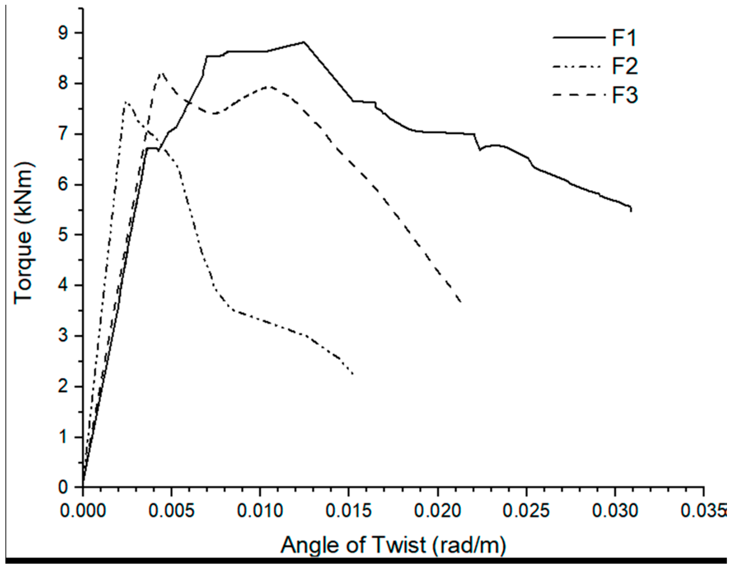
| lau et al. [39] | F1 | 1300 | 150 | 250 | The Double end hooked Dramix 5D 65/60BG steel fibers | 66.7 | 12.500 | 0.50 | 56.000 | Fly ash, silica, fumes and ground granulated furnace slag | 0.45 | 1:1.23:1.93 | 4–7 mm | Alkali activators | |||
| F2 | 66.7 | 12.500 | 0.50 | 56.000 | |||||||||||||
| F3 | 66.7 | 12.500 | 0.50 | 56.000 | |||||||||||||
| R1 | 12.500 | 0.50 | 157.000 | 157.000 | 393.000 | 56.000 | |||||||||||
| R2 | 12.500 | 0.50 | 157.000 | 157.000 | 393.000 | 56.000 | |||||||||||
| R3 | 12.500 | 0.50 | 157.000 | 157.000 | 393.000 | 56.000 | |||||||||||
| RF2 | 66.7 | 12.500 | 0.50 | 157.000 | 157.000 | 393.000 | 56.000 | ||||||||||
| RF3 | 66.7 | 12.500 | 0.50 | 157.000 | 157.000 | 393.000 | 56.000 | ||||||||||
| George & Sofi [56] | NWC-0% | 1100 | 100 | 150 | 101.000 | 101.000 | 207.000 | 32.200 | OPC of 53 grade | 0.5 | 1:77:3.1 | 12.5–20 mm | |||||
| NWC-0.5% | Grooved steel fibres | 50 | 0.50 | 101.000 | 101.000 | 207.000 | 44.200 | ||||||||||
| NWC-0.75% | 50 | 0.75 | 101.000 | 101.000 | 207.000 | 58.970 | |||||||||||
| NWC-1% | 50 | 1.00 | 101.000 | 101.000 | 207.000 | 59.970 | |||||||||||
| CSC-0% | - | 101.000 | 101.000 | 207.000 | 30.167 | OPC of 53 grade and Silica fume | 0.31 | 1:1.37:0.91 | 12.5 mm | Superplasticizer (Cer Hyperplast XR-W40) at 0.7% by wt. of binder. | |||||||
| CSC-0.5% | Grooved steel fibres | 50 | 0.50 | 101.000 | 101.000 | 207.000 | 35.360 | ||||||||||
| CSC-0.75% | 50 | 0.75 | 101.000 | 101.000 | 207.000 | 35.600 | |||||||||||
| CSC-1% | 50 | 1.00 | 101.000 | 101.000 | 207.000 | 36.600 |
| References | Specimens | Beam Length | Beam Width | Beam Depth | Fibre Type | Aspect Ratio | Specific Gravity | Supplied Steel Dosage | Volume of Reinforcement to Volume of Composite | Cu, Concrete (N/mm2) | Type of Cement | W/C | Mix Proportion | Size of Coarse Agreggates | Admixtures |
|---|---|---|---|---|---|---|---|---|---|---|---|---|---|---|---|
| Usman et al. [57] | S1-0% | 250 | 25 | 80 | Polypropylene | 0.013 | Ferrocement | ||||||||
| S2-0% | 0.025 | ||||||||||||||
| S3-0% | 0.038 | ||||||||||||||
| S4-0.3% | 0.30 | 0.013 | |||||||||||||
| S5-0.3% | 0.30 | 0.025 | |||||||||||||
| S6-0.6% | 0.30 | 0.038 | |||||||||||||
| S7 -0.6% | 0.60 | 0.013 | |||||||||||||
| S8-0.6% | 0.60 | 0.025 | |||||||||||||
| S9-0.9% | 0.60 | 0.038 | |||||||||||||
| S10 -0.9% | 0.90 | 0.013 | |||||||||||||
| S11-0.9% | 0.90 | 0.025 | |||||||||||||
| S12-0.9% | 0.90 | 0.025 | |||||||||||||
| Zhou et al. [38] | S-1 | 1800 | 150 | 200 | OC | 0.021 | 42.500 | OPC | 0.4 | 1:1.46:0.86 | 4–15 mm | ||||
| S-2 | 0.041 | 42.500 | 1:1.46:0.86 | ||||||||||||
| F-1 | FRC with Polypropylene | 1000 | 9.1 | 1.00 | 0.021 | 40.200 | OPC and Fly ash at 214 kg/m3 | 0.57 | 1:1.18:0.79 | Plasticizer at 4.25 kg/m3 | |||||
| F-2 | 1000 | 9.1 | 1.00 | 0.041 | 40.200 | 1:1.18:0.80 | |||||||||
| F-3 | 1000 | 9.1 | 1.00 | 0.021 | 40.200 | 1:1.18:0.81 | |||||||||
| F-4 | 1000 | 9.1 | 1.00 | 0.041 | 40.200 | 1:1.18:0.82 | |||||||||
| E-1 | 1000 | 13.65 | 1.50 | 0.021 | 32.800 | OPC and Fly ash at 265 kg/m3 | 0.54 | 1:1 | |||||||
| E-2 | 1000 | 13.65 | 1.50 | 0.040 | 32.800 | 1:1 |
| References | Specimens | Beam Length | Beam Width | Beam Depth | Fibre Type | Aspect Ratio | Specific Gravity | Supplied Steel Dosage | Area of Steel at Bottom | Area of Steel at Top | Area of Steel for Shear Links | Cu, Concrete (N/mm2) | Type of Cement | W/C | Mix Proportion | Admixtures |
|---|---|---|---|---|---|---|---|---|---|---|---|---|---|---|---|---|
| Saravanakumar et al. [58] | HFRC0.0 | 1200 | 150 | 230 | 151.000 | 101.000 | 335.000 | 21.500 | OPC 53 grade | 1:1.41:3.09 | Sulphonated napthalene polymer based super plasticizer SP 430 | |||||
| HFRC0.5 | Corrugated circular Steel fibres of size 1 mm × 36 mm with avg. pitch of 8 mm and rise of 2 mm; Avg. ultimate strenght of 600 Mpa and Modulus of elasticity of 210,000 MPa and Glass fibres having diameter of 0.0153 mm, relative density of 2.7 g/m3, ultimate tensile strength of 2900 MPa, elastic modulus of 73.4 MPa. | 151.000 | 101.000 | 335.000 | 23.300 | |||||||||||
| HFRC1.0 | 151.000 | 101.000 | 335.000 | 26.400 | ||||||||||||
| HFRC1.5 | 151.000 | 101.000 | 335.000 | 24.300 | ||||||||||||
| Hassan et al. [59] | C (Solid beam without fiber) | 1000 | 150 | 150 | 1:1.56:2.44 | |||||||||||
| H (Hollow beam (75 mm dia hollow) without fibre) | Synthetic fibers of lengths 19 mm, 38 mm and 57 mm, and steel fibers of length 13 mm and diameter ranging from 0.2 to 0.3 mm | 157.000 | 157.000 | 400.000 | OPC | 0.32 | Superplasticizer of 1/100 kg cement | |||||||||
| HS (Hollow beam reinf. With ST. F | 157.000 | 157.000 | 400.000 | |||||||||||||
| H20 (Hollow beam reinf. With SY. F of 19 mm length) | 157.000 | 157.000 | 400.000 | |||||||||||||
| H30 (Hollow beam reinf. With SY.F 37 mm length) | 157.000 | 157.000 | 400.000 | |||||||||||||
| H50 (Hollow beam with SY.F of 55 mm of length) | 157.000 | 157.000 | 400.000 | |||||||||||||
| References | Specimens | Beam Length | Beam Width | Beam Depth | Fibre Type | Area of Steel at Bottom | Area of Steel at Top | Area of Steel for Shear Links | Cu, Concrete (N/mm2) | Type of Cement | W/C | Mix Proportion |
|---|---|---|---|---|---|---|---|---|---|---|---|---|
| Tudu [60] | Beam No. 1 (Control Beam) | 1650 | 150 | 250 | 402.000 | 157.000 | 188.000 | 27.110 | OPC | 0.5 | 1:1.8:3.6 | |
| Beam No. 2 (Uni-GFRP continuous fully wrap) | Glass fiber reinforced polymer (GFRP) | 402.000 | 157.000 | 188.000 | 31.000 | 1:1.8:3.6 | ||||||
| Beam No. 3 (Bi-GFRP Continuous fully wrap) | 402.000 | 157.000 | 188.000 | 29.340 | 1:1.8:3.6 | |||||||
| Beam No. 4 (10 cm Uni-GFRP strips wrap) | 402.000 | 157.000 | 188.000 | 30.250 | 1:1.8:3.6 | |||||||
| Beam No. 5 (10 cm Bi-GFRP) | 402.000 | 157.000 | 188.000 | 28.530 | 1:1.8:3.6 | |||||||
| Beam No. 6 (5 cm Uni-GFRP strips wrap) | 402.000 | 157.000 | 188.000 | 25.780 | 1:1.8:3.6 | |||||||
| Beam No. 7 (5 cm Bi-GFRP strips wrap) | 402.000 | 157.000 | 188.000 | 27.360 | 1:1.8:3.6 | |||||||
| Beam No. 8 (5 cm Uni-GFRP strips wrap at 45 degrees) | 402.000 | 157.000 | 188.000 | 30.000 | 1:1.8:3.6 | |||||||
| Beam No. 9 (5 cm Bi-GFRP strips wrap at 45 degrees) | 402.000 | 157.000 | 188.000 | 31.500 | 1:1.8:3.6 |
| References | Specimens | Beam Length | Beam Width | Beam Depth | Fibre Type | Aspect Ratio | Specific Gravity | Supplied Steel Dosage | Area of Steel at Bottom | Area of Steel at Top | Area of Steel for Shear Links | Cu, Concrete (N/mm2) | Type of Cement | W/C | Mix Proportion | Size of Coarse Agreggates |
|---|---|---|---|---|---|---|---|---|---|---|---|---|---|---|---|---|
| Tibhe & Rathi [61] | Control Beam | 1200 | 150 | 300 | 339.000 | 101.000 | 203.000 | 30.000 | OPC 53 grade Ultra tech | 0.45 | 1:1.76:2.77 | 4–20 mm | ||||
| CFB1 | Carbon fibre reinforced polymer (CFRP) with young’s modulus of 70–90, tensile strength of 2400–5100 MPa, strain at failure of 0.5–1.73 and density of 1.85–1.9 andGlass fibre reinforced polymer (GFRP) with young modulus of 390–760 GPa, tensile strength of 3000–4800 MPa, strain at failure of 3.5–5.5% and density of 2.5–2.6 g/cm2) | 339.000 | 101.000 | 203.000 | 30.000 | |||||||||||
| GFB1 | 339.000 | 101.000 | 203.000 | 30.000 | ||||||||||||
| CFB2 | 339.000 | 101.000 | 203.000 | 30.000 | ||||||||||||
| GFB2 | 339.000 | 101.000 | 203.000 | 30.000 | ||||||||||||
| CFB3 | 339.000 | 101.000 | 203.000 | 30.000 | ||||||||||||
| GFB3 | 339.000 | 101.000 | 203.000 | 30.000 | ||||||||||||
| CFB4 | 339.000 | 101.000 | 203.000 | 30.000 | ||||||||||||
| GFB4 | 339.000 | 101.000 | 203.000 | 30.000 | ||||||||||||
| CFB5 | 339.000 | 101.000 | 203.000 | 30.000 | ||||||||||||
| GFB5 | 339.000 | 101.000 | 203.000 | 30.000 | ||||||||||||
| CFB6 | 339.000 | 101.000 | 203.000 | 30.000 | ||||||||||||
| GFB6 | 339.000 | 101.000 | 203.000 | 30.000 | ||||||||||||
| Chalioris [62] | Ra-c | Carbon fibre reinforced polymer (CFRP) with thickness 0.11 mm, elastic modulus of 230 GPa, Ultimate tensile strength of 3900 MPa, elongation at failure 1.5%mm/m | 27.500 | |||||||||||||
| Ra-Fs150(2) | 1600 | 150 | 300 | 101.000 | 101.000 | 27.500 | ||||||||||
| Ra-S | 101.000 | 101.000 | 226.000 | 27.500 | ||||||||||||
| Ra-SFs150(2) | 1600 | 150 | 300 | 101.000 | 101.000 | 226.000 | 27.500 | |||||||||
| Rb-c | 101.000 | 101.000 | 28.800 | |||||||||||||
| Rb-Fs200(1) | 1600 | 200 | 300 | 101.000 | 101.000 | 28.800 | ||||||||||
| Rb-S | 101.000 | 101.000 | 283.000 | 28.800 | ||||||||||||
| Rb-SFs200(1) | 1600 | 200 | 300 | 101.000 | 101.000 | 283.000 | 28.800 | |||||||||
| References | Specimens | Beam Length | Beam Width | Beam Depth | Fibre Type | Aspect Ratio | Specific Gravity | Supplied Steel Dosage | Area of Steel at Bottom | Area of Steel at Top | Area of Steel for Shear Links | Cu, Concrete (N/mm2) | W/C | Mix Proportion |
|---|---|---|---|---|---|---|---|---|---|---|---|---|---|---|
| Kandekar et al. [3] | C1 (Controlled beam) | 1000 | 150 | 300 | Aramid | 151.000 | 101.000 | 335.000 | 30.000 | 0.45 | 1:2.14:3.54 | |||
| C2 (Conctrolled Beam) | 151.000 | 101.000 | 335.000 | 30.000 | ||||||||||
| C3 (Controlled Beam) | 151.000 | 101.000 | 335.000 | 30.000 | ||||||||||
| T1 (Designed ror Torsion) | 151.000 | 101.000 | 335.000 | 30.000 | ||||||||||
| T2 (Designed ror Torsion) | 151.000 | 101.000 | 335.000 | 30.000 | ||||||||||
| T3 (Designed ror Torsion) | 151.000 | 101.000 | 335.000 | 30.000 | ||||||||||
| F1 (fully wrapped beam) | Aramid fiber properties; weave style is plain, Areal weight of fabric is 300 g/m2, standard with is 1000 mm, dry fabric thickness is 0.25 mm; Tensile strength is 2400–3600 MPa, Tensile Modulus is 60–120 GPa, Elongation percentage 2.2–4.4% | 151.000 | 101.000 | 335.000 | 30.000 | |||||||||
| F2 (fully wrapped beam) | 151.000 | 101.000 | 335.000 | 30.000 | ||||||||||
| F3 (fully wrapped beam) | 151.000 | 101.000 | 335.000 | 30.000 | ||||||||||
| S1 (Wrapped with strip) | 151.000 | 101.000 | 335.000 | 30.000 | ||||||||||
| S2 (wrapped with strip) | 151.000 | 101.000 | 335.000 | 30.000 | ||||||||||
| S3 (wrapped with strip) | 151.000 | 101.000 | 335.000 | 30.000 | ||||||||||
| References | Specimens | Beam Width | Beam Depth | Longitudinal Rebar Ratio (%) | Fibre Volume Fraction (%) | Fibre Volume Fraction/0.25% | Ultimate Torque | Ultimate Torque/Torque at First Crack | Ultimate Twist/Twist at First Crack | Torsional Strength Increase (Based on Optimal and Relevant Strengthening Configuration)% |
|---|---|---|---|---|---|---|---|---|---|---|
| Amin and Bentz, 2018 | T-0-8 | 200.00 | 280.00 | 1.36 | 16.00 | 37.00 | ||||
| T-0-10 | 1.36 | 16.00 | ||||||||
| T-30-8 | 1.36 | 0.38 | 1.52 | 21.00 | ||||||
| T-30-10 | 1.36 | 0.38 | 1.52 | 23.00 | ||||||
| Facconi et al. 2021 | TB1-PC | 300.00 | 300.00 | 1.13 | 16.18 | 1.30 | 1.60 | 55.43 | ||
| TB2-PC-ST | 1.13 | 20.84 | 1.59 | 22.97 | ||||||
| TB3-SFRC25 | 1.13 | 0.32 | 1.28 | 27.32 | 2.04 | 17.48 | ||||
| TB4-SFRC25 | 1.13 | 0.32 | 1.28 | 22.94 | 1.91 | 9.40 | ||||
| TB5-SFRC50 | 1.13 | 0.63 | 2.52 | 26.94 | 1.94 | 15.19 | ||||
| TB6-SFRC50 | 1.13 | 0.63 | 2.52 | 24.63 | 1.79 | 8.99 | ||||
| Patil et al. 2016 | FR0 | 150.00 | 150.00 | 0.90 | 2.26 | 72.00 | ||||
| FR0.5 | 0.90 | 0.50 | 2.00 | 2.50 | ||||||
| FR1 | 0.90 | 1.00 | 4.00 | 2.96 | ||||||
| FR1.5 | 0.90 | 1.50 | 6.00 | 3.07 | ||||||
| lau et al. [39] | F1 | 150.00 | 250.00 | 0.50 | 2.00 | 8.80 | 1.31 | 3.29 | 25.00 | |
| F2 | 0.50 | 2.00 | 7.70 | 1.00 | 1.00 | |||||
| F3 | 0.50 | 2.00 | 8.30 | 1.04 | 1.07 | |||||
| R1 | 0.84 | 0.50 | 2.00 | 9.80 | 1.72 | 3.12 | ||||
| R2 | 0.84 | 0.50 | 2.00 | 7.60 | 1.31 | 1.30 | ||||
| R3 | 0.84 | 0.50 | 2.00 | 7.70 | 1.03 | 1.13 | ||||
| RF2 | 0.84 | 0.50 | 2.00 | 10.10 | 1.40 | 3.33 | ||||
| RF3 | 0.84 | 0.50 | 2.00 | 10.80 | 1.38 | 3.59 | ||||
| George & Sofi [56] | NWC-0% | 100.00 | 150.00 | 1.35 | 2.55 | 1.19 | 155.37 | |||
| NWC-0.5% | 1.35 | 0.50 | 2.00 | 4.05 | 1.06 | |||||
| NWC-0.75% | 1.35 | 0.75 | 3.00 | 6.51 | 1.09 | |||||
| NWC-1% | 1.35 | 1.00 | 4.00 | 6.22 | 1.11 | |||||
| CSC-0% | 1.35 | 4.80 | 1.10 | |||||||
| CSC-0.5% | 1.35 | 0.50 | 2.00 | 5.33 | 1.04 | |||||
| CSC-0.75% | 1.35 | 0.75 | 3.00 | 7.25 | 1.08 | |||||
| CSC-1% | 1.35 | 1.00 | 4.00 | 6.51 | 1.06 |
| References | Specimens | Beam Width | Beam Depth | Longitudinal Rebar Ratio (%) | Fibre Volume Fraction (%) | Fibre Volume Fraction/0.25% | Ultimate Torque | Ultimate Torque/Torque at First Crack | Torsional Strength Increase (Based on Optimal and Relevant Strengthening Configuration) % |
|---|---|---|---|---|---|---|---|---|---|
| Usman et al. [57] | S1-0% | 25.00 | 80.00 | 1.26 | 0.05 | 39.00 | |||
| S2-0% | 2.51 | 0.05 | |||||||
| S3-0% | 3.77 | 0.05 | |||||||
| S4-0.3% | 1.26 | 0.30 | 1.20 | 0.05 | |||||
| S5-0.3% | 2.51 | 0.30 | 1.20 | 0.06 | |||||
| S6-0.3% | 3.77 | 0.30 | 1.20 | 0.07 | |||||
| S7-0.6% | 1.26 | 0.60 | 2.40 | 0.06 | |||||
| S8-0.6% | 2.51 | 0.60 | 2.40 | 0.07 | |||||
| S9-0.6% | 3.77 | 0.60 | 2.40 | 0.08 | |||||
| S10-0.9% | 1.26 | 0.90 | 3.60 | 0.05 | |||||
| S11-0.9% | 2.51 | 0.90 | 3.60 | 0.05 | |||||
| S12-0.9% | 2.51 | 0.90 | 3.60 | 0.06 | |||||
| Zhou et al. [38] | S-1 | 150.00 | 200.00 | 2.05 | 5.45 | 1.89 | |||
| S-2 | 4.10 | 5.83 | 2.10 | ||||||
| F-1 | 2.05 | 1.00 | 4.00 | 6.67 | 2.32 | 15.18 | |||
| F-2 | 4.10 | 1.00 | 4.00 | 7.00 | 2.32 | ||||
| F-3 | 2.05 | 1.00 | 4.00 | 5.70 | 2.05 | ||||
| F-4 | 4.10 | 1.00 | 4.00 | 6.43 | 2.52 | ||||
| E-1 | 2.05 | 1.50 | 6.00 | 8.23 | 3.61 | 49.23 | |||
| E-2 | 4.00 | 1.50 | 6.00 | 8.70 | 3.95 |
| Specimen | Configuration |
|---|---|
| C | Solid beam specimen without fibre |
| H | Hollow beam specimen without fibre |
| HS | Hollow beam specimen reinforced with ST. F |
| H20 | Hollow beam specimen reinforced with SY. F of 19 mm Length |
| H30 | Hollow beam specimen reinforced with SY. F 37 mm Length |
| H50 | Hollow beam specimen reinforced with SY. F of 55 mm Length |
| References | Specimens | Beam Width | Beam Depth | Longitudinal Rebar Ratio (%) | Fibre Volume Fraction (%) | Fibre Volume Fraction/0.25% | Ultimate Torque | Ultimate Torque/Torque at First Crack | Ultimate Twist/Twist at First Crack | Torsional Strength Increase (Based on Optimal and Relevant Strengthening Configuration) % |
|---|---|---|---|---|---|---|---|---|---|---|
| Saravanakumar et al. [58] | HFRC0.0 | 150.00 | 230.00 | 0.73 | - | - | 4.70 | 1.15 | 36.17 | |
| HFRC0.5 | 0.73 | 0.50 | 2.00 | 5.20 | 1.16 | |||||
| HFRC1.0 | 0.73 | 1.00 | 4.00 | 6.10 | 1.17 | |||||
| HFRC1.5 | 0.73 | 1.50 | 6.00 | 6.40 | 1.17 | |||||
| Hassan et al. [59] | C (Solid beam without fibre) | 150.00 | 150.00 | 6.40 | 1.60 | 2.52 | 21.88 | |||
| H (Hollow beam (75 mm dia hollow) without fibre) | 1.40 | 6.20 | 1.77 | 3.26 | ||||||
| HS (Hollow beam reinf. with 13 mm ST. F | 1.40 | 0.25 | 1.00 | 6.75 | 1.59 | 3.76 | ||||
| H20 (Hollow beam reinf. with SY. F of 19 mm length) | 1.40 | 0.50 | 2.00 | 6.96 | 1.64 | 3.27 | ||||
| H30 (Hollow beam reinf. with SY.F 37 mm length) | 1.40 | 0.75 | 3.00 | 7.00 | 1.65 | 3.27 | ||||
| H50 (Hollow beam with SY.F of 55 mm of length) | 1.40 | 1.00 | 4.00 | 7.80 | 1.73 | 4.91 |
| References | Specimens | Beam Width | Beam Depth | Longitudinal Rebar Ratio (%) | Fibre Strip Width (mm) | Fibre Thickness (mm) | Ultimate Torque | Ultimate Torque/Torque at First Crack | Ultimate Twist/Twist at First Crack | Torsional Strength Increase (Based on Optimal and Relevant Strengthening Configuration) % |
|---|---|---|---|---|---|---|---|---|---|---|
| A. Glass Fibre Reinforced Polymer | ||||||||||
| Tudu [60] | Beam No. 1 (Control Beam) | 150.00 | 250.00 | 1.49 | - | 35.10 | 1.63 | 2.00 | 54.62 | |
| Beam No. 2 (Uni-GFRP continuous fully wrap) | 1.49 | 25.00 | 1.50 | 66.13 | 2.72 | 1.34 | ||||
| Beam No. 3 (Bi-GFRP Continuous fully wrap) | 1.49 | 25.00 | 3.00 | 56.70 | 1.62 | 1.28 | ||||
| Beam No. 4 (10 cm Uni-GFRP strips wrap) | 1.49 | 25.00 | 100.00 | 48.60 | 1.80 | 2.25 | ||||
| Beam No. 5 (10 cm Bi-GFRP) | 1.49 | 25.00 | 100.00 | 58.05 | 1.79 | 3.16 | ||||
| Beam No. 6 (5 cm Uni-GFRP strips 90o wrap) | 1.49 | 25.00 | 50.00 | 46.98 | 2.18 | 3.78 | ||||
| Beam No. 7 (5 cm Bi-GFRP strips 90o wrap) | 1.49 | 25.00 | 50.00 | 58.32 | 1.96 | 2.25 | ||||
| Beam No. 8 (5 cm Uni-GFRP strips wrap at 45 degrees) | 1.49 | 25.00 | 50.00 | 54.00 | 2.22 | 2.05 | ||||
| Beam No. 9 (5 cm Bi-GFRP strips wrap at 45 degrees) | 1.49 | 25.00 | 50.00 | 54.54 | 1.84 | 2.51 | ||||
| References | Specimens | Beam Width | Beam Depth | Longitudinal Rebar Ratio (%) | Fibre Strip Width (mm) | Fibre Thickness (mm) | Ultimate Torque | Ultimate Torque/Torque at First Crack | Ultimate Twist/Twist at First Crack | Torsional Strength Increase (Based on Optimal and Relevant Strengthening Configuration) % |
|---|---|---|---|---|---|---|---|---|---|---|
| B. Carbon Fibre Reinforced Polymer | ||||||||||
| Tibhe & Rathi [61] | ControlBeam | 150.00 | 300.00 | 0.98 | 12.22 | 2.33 | 18.12 | 101.80 | ||
| CFB1 | 0.98 | 150.00 | 19.61 | 2.35 | 16.33 | |||||
| GFB1 | 0.98 | 150.00 | 18.02 | 2.40 | 15.19 | |||||
| CFB2 | 0.98 | 150.00 | 17.11 | 2.12 | 15.41 | |||||
| GFB2 | 0.98 | 150.00 | 15.40 | 2.21 | 15.63 | |||||
| CFB3 | 0.98 | 150.00 | 17.12 | 2.04 | 15.81 | |||||
| GFB3 | 0.98 | 150.00 | 13.29 | 1.84 | 15.08 | |||||
| CFB4 | 0.98 | 150.00 | 21.87 | 2.34 | 15.08 | |||||
| GFB4 | 0.98 | 150.00 | 19.02 | 2.48 | 15.29 | |||||
| CFB5 | 0.98 | 150.00 | 22.47 | 2.24 | 12.93 | |||||
| GFB5 | 0.98 | 150.00 | 20.62 | 2.41 | 15.01 | |||||
| CFB6 | 0.98 | 150.00 | 24.66 | 2.02 | 11.75 | |||||
| GFB6 | 0.98 | 150.00 | 22.42 | 2.13 | 13.15 | |||||
| Chalioris [62] | Ra-c (no stirrups) | 2.39 | 1.00 | 79.67 | ||||||
| Ra-Fs150(2) (no stirrups) | 150.00 | 300.00 | 0.45 | 150.00 | 0.22 | 3.02 | 1.36 | |||
| Ra-S (with stirrups) | 2.41 | 1.07 | ||||||||
| Ra-SFs150(2) (with stirrups) | 150.00 | 300.00 | 0.45 | 150.00 | 0.22 | 4.33 | 1.84 | |||
| Rb-c (no stirrups) | 6.95 | 1.00 | ||||||||
| Rb-Fs200(1) (no stirrups) | 200.00 | 300.00 | 0.34 | 200.00 | 0.11 | 9.32 | 1.38 | |||
| Rb-S (with stirrups) | 7.15 | 1.04 | ||||||||
| Rb-SFs200(1) (with stirrups) | 200.00 | 300.00 | 0.34 | 200.00 | 0.11 | 9.80 | 1.41 | |||
| References | Specimens | Beam Width | Beam Depth | Longitudinal Rebar Ratio (%) | Fibre Strip Width (mm) | Fibre Thickness (mm) | Ultimate Torque | Ultimate Torque/Torque at First Crack | Torsional Strength Increase (Based on Optimal and Relevant Strengthening Configuration) % |
|---|---|---|---|---|---|---|---|---|---|
| Kandekar & Talikoti [3] | C1 (Controlled beam) | 150.00 | 300.00 | 0.56 | 3.30 | 1.22 | |||
| C2 (Conctrolled Beam) | 0.56 | 2.90 | 1.21 | ||||||
| C3 (Controlled Beam) | 0.56 | 3.00 | 1.20 | ||||||
| T1 (Designed for Torsion) | 0.78 | 7.80 | 1.22 | 166.67 | |||||
| T2 (Designed for Torsion) | 0.78 | 8.50 | 1.23 | ||||||
| T3 (Designed for Torsion) | 0.78 | 8.50 | 1.25 | ||||||
| F1 (fully wrapped beam) | 0.56 | 1000.00 | 0.25 | 8.95 | 1.42 | 173.66 | |||
| F2 (fully wrapped beam) | 0.56 | 1000.00 | 0.25 | 8.50 | 1.20 | ||||
| F3 (fully wrapped beam) | 0.56 | 1000.00 | 0.25 | 8.00 | 1.16 | ||||
| S1 (Wrapped with strip) | 0.56 | 1000.00 | 0.25 | 6.65 | 1.28 | 102.69 | |||
| S2 (wrapped with strip) | 0.56 | 1000.00 | 0.25 | 6.00 | 1.25 | ||||
| S3 (wrapped with strip) | 0.56 | 1000.00 | 0.25 | 6.20 | 1.24 |
Publisher’s Note: MDPI stays neutral with regard to jurisdictional claims in published maps and institutional affiliations. |
© 2022 by the authors. Licensee MDPI, Basel, Switzerland. This article is an open access article distributed under the terms and conditions of the Creative Commons Attribution (CC BY) license (https://creativecommons.org/licenses/by/4.0/).
Share and Cite
Awoyera, P.O.; Effiong, J.U.; Olalusi, O.B.; Prakash Arunachalam, K.; de Azevedo, A.R.G.; Martinelli, F.R.B.; Monteiro, S.N. Experimental Findings and Validation on Torsional Behaviour of Fibre-Reinforced Concrete Beams: A Review. Polymers 2022, 14, 1171. https://doi.org/10.3390/polym14061171
Awoyera PO, Effiong JU, Olalusi OB, Prakash Arunachalam K, de Azevedo ARG, Martinelli FRB, Monteiro SN. Experimental Findings and Validation on Torsional Behaviour of Fibre-Reinforced Concrete Beams: A Review. Polymers. 2022; 14(6):1171. https://doi.org/10.3390/polym14061171
Chicago/Turabian StyleAwoyera, Paul Oluwaseun, John Uduak Effiong, Oladimeji Benedict Olalusi, Krishna Prakash Arunachalam, Afonso R. G. de Azevedo, Flavia R. B. Martinelli, and Sergio Neves Monteiro. 2022. "Experimental Findings and Validation on Torsional Behaviour of Fibre-Reinforced Concrete Beams: A Review" Polymers 14, no. 6: 1171. https://doi.org/10.3390/polym14061171
APA StyleAwoyera, P. O., Effiong, J. U., Olalusi, O. B., Prakash Arunachalam, K., de Azevedo, A. R. G., Martinelli, F. R. B., & Monteiro, S. N. (2022). Experimental Findings and Validation on Torsional Behaviour of Fibre-Reinforced Concrete Beams: A Review. Polymers, 14(6), 1171. https://doi.org/10.3390/polym14061171