Abstract
Pultruded glass fibre reinforced polymer (pGFRP) composites provide outstanding properties for composite polymer cross arms in power transmission line applications. This study has investigated the effects of various stacking sequences of fibres directions of pGFRP on flexural strength and creep behaviour. The use of static four-point bending flexural tests revealed that Stacking Sequence 2 (±45/0/90/0/90/0) had a significant flexural strength of 399.9 MPa while Stacking Sequence 1 (±45/90/0/±45) had a flexural strength of 242.5 MPa. Furthermore, the four-point bending creep experiments were performed at three distinct stress levels, notably 12%, 24%, and 37% of the ultimate flexural strength, to characterise the creep behaviour of distinct stacking sequences. Moreover, Findley’s power law equation for bending creep behaviour has revealed that the time-dependent reduction factor of Stacking Sequence 1 and Stacking Sequence 2 estimates a drop in flexural modulus of 23% and 10% respectively.
Keywords:
stacking sequence; pultrusion; creep; glass fibres-reinforced polymer; flexural; cross arm 1. Introduction
An overhead power line transmission tower, also known as a power tower or an electricity pylon, is generally a large structure made of steel lattice that supports the line. Generally, 132 kV, 275 kV, and 500 kV are the main electrical cable types used in power line transmission tower systems [1,2]. Over time, polymeric materials have replaced wooden cross arms in transmission towers due to several factors, such as the drastic decline of timber resources and cost-effectiveness [3,4,5]. Due to its non-conductivity and high dielectric strength, the pultruded glass fibre reinforced polymer (pGFRP) cross arm serves as a surplus component for an insulator, where the combined insulation improves the lightning impulse voltage performance of an electrical power line’s distribution and transmission line construction. Simultaneously, the pGFRP cross arm has evolved to withstand transmission line assemblies, however, one of the difficulties linked with these materials’ behaviour in fabrication is its high tendency towards creep effects.
Creep is defined as a time-dependent plastic deformation that occurs at elevated temperatures and with constant stress lower than the yield stress. However, while polymers exhibit a similar time-dependent deformation that is viscoelastic in nature, their behaviour presents the characteristics of elastic solids [6,7,8,9,10]. Meanwhile, the creep phenomenon of FRP is significant because it can endanger the dependability and durability of structural components and have a tendency to buckle permanently as a result of mechanical pressures caused by long-term interaction with high levels of stress [10,11,12,13]. Although there are various fabrication processes for producing GFRP structures, the pultrusion method was extensively used to produce hollow tubes, such as the pGFRP cross arm. This is because using the pultruded composite method to create pGFRP cross arm structures has many advantages, such as strength, lightness, stiffness, easy and rapid installation, anti-corrosion, and acoustic insulation [14,15,16]. The pultrusion method enables the fabrication of prismatic profiles in which fibre orientation is optimised and orientated longitudinally [17,18]. Furthermore, the mechanical characteristics of pGFRP composites in the pultrusion technique are influenced by various factors, such as fibre volume, interphase matrix, fibre orientation, stacking sequence, and others [19,20].
The advantages of composite cross arms are that they provide robust performance. Because of this, they are used as anchor points, designed to replace wooden structures at the dead-end assemblies within transmission and distribution systems. Likewise, pGFRP cross-arms have been employed as cantilever beams for street light support structures as they are a good choice when supplying arm supports for attaching outdoor components to utility poles [2,21]. However, pGFRPs are often subject to extreme outdoor exposure and constant loads for extended periods of time, resulting in a behaviour known as structural collapse, which occurs due to creep deformation. Therefore, creep behaviour is a critical issue for materials that have endured loads for extended periods of time [2,22,23,24]. The study by Beddu et al. [25] of the creep behaviour in GFRP cross arms indicates that the initial creep response causes the cross arm to change size and shape when subjected to long-term loading. An illustration of a cutaway cross arm is shown in Figure 1.
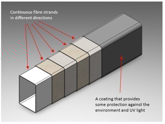
Figure 1.
Cutaway illustration of pGFRP cross arm.
The biaxial fibre stacking sequence pultrusion technique is used in pGFRP cross arms because it integrates different forms of oriented fibres; biaxially and oriented polymeric fibres/fillers inside the matrix interact with each other as load-bearing components, an effect comparable to incorporating several materials in of woven textiles [20,26]. The fibre stacking sequence plays a significant part in the enhancement of mechanical properties. As such, woven textiles are one of the most effective reinforcing structures for facilitating physical interferences within reinforced fibre and matrix systems. Furthermore, the stacking sequence contributes significantly to a change in the mechanical characteristics and performance of pGFRP cross arms in transmission tower construction [19,27]. While investigating the effects of stacking sequences upon various mechanical properties and the failure mode responses of quasi-static compression loads [27,28,29,30], numerous computational models were considered. However, the four-element burgers (FEB) model and the Findley power law (FPL) model are among the most prevalent [1,8,31,32,33].
While there are other models to describe the behaviour of GFRP when subjected to creep, Findley’s power law model has proven to be reliable and accurate, in addition to being easy and simple to use [8,31]. Hence, this paper will use Findley’s power law to model the behaviour of pGFRP and predict losses in stiffness due to creep. The aim of this study is first to determine the ultimate flexural strength of each sequence by using four-point bending tests to calculate the respective creep load levels, then perform the creep tests. We studied two pGFRP cross arm sequence layouts, Stacking Sequence 1 (±45/90/0/±45) and Stacking Sequence 2 (±45/0/90/0/90/0), with a total thickness of 6 mm and 7 mm, respectively. The coupons produced via the pGFRP cross arms have been subjected to four-point bending creep tests for a period of 720 h at three different load levels for each respective sequence. Finally, Findley power law parameters were obtained to highlight the difference in creep performance between the sequences and calculate the reduction factor.
2. Material and Methodology
2.1. Cross Arm Fabrication
Pultrusion is a continuous manufacturing process for stable cross-section composite materials. The pGFRP cross arm has been integrated with a high-strength fibreglass mat, which, when merged with a reinforced fibreglass strand, provides multi-directional reinforcement and resistance. In other words, unidirectional fibres are arranged in layers separated by continuous strand-mats, as illustrated in Figure 2. These components are integrated and immersed in a liquid resin mixture before being pulled through a hot steel-forming die. As a result, a robust, fibreglass-reinforced composite structure is created that will never deteriorate, unlike wood. The coupon samples used for the testing were taken from the wall segments of hollow tubes of the pGFRP cross arm, which were manufactured via the pultrusion technique by various vendors. The pGFRP hollow tubes were acquired from two different sequences of fibre arrangements and layered with distinct stacking sequences. Both sequences use polyester resin and glass fibres with a fibre volume fraction, , of 62% and 70% for Sequence 1 and Sequence 2, respectively, while the remaining volume fraction, 100%, is the used resin. Table 1 presents the material properties in each sequence. The fibre direction plies/stacking sequence of the samples is described as the following sequence:
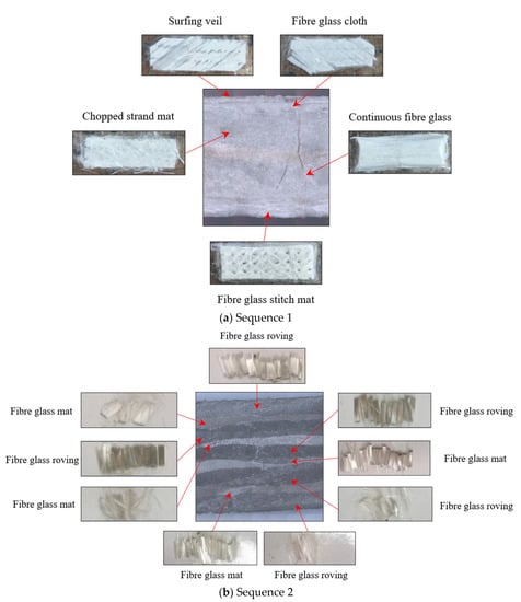
Figure 2.
Breakdown of fibres plies in pGFRP cross-section: (a) Sequence 1; (b) Sequence 2.

Table 1.
Material properties of Sequence 1 and Sequence 2.
Sequence 1: (±45/90/0/±45) with a thickness of 6 mm.
Sequence 2: (±45/0/90/0/90/0) with a thickness of 7 mm.
A total of six replicate coupon samples for each stacking sequence were cut from pGFRP hollow tubes with the same dimensions of 38 mm × 380 mm. Three samples were tested in static failure four-point bending tests, and the remaining three were used in flexural creep tests at three different load levels, with one specimen at each load level.
2.2. Fibre Volume Fraction
The stacking sequence parameter becomes one that contributes to the quantity of resin to fibre ratio while producing the pGFRP composite cross arm. As a result, the ASTM D2584 [34] was utilised as a guideline to analyse the variations in fibre volume fraction, which impacts the amount of resin that may be absorbed by fibres. One of the elements influencing the general mechanical characteristics of composite structures is the fibre percentage of fibre reinforcement in stacking sequence composite structures [27,35]. The pultrusion technique’s customised design of the stacking sequence at various interlaminar of glass fibre incorporation has impacted diversity, strength, and behaviour.
The pGFRP tubes were cut into 20 mm × 20 mm pieces and subjected to burn-off tests in accordance with the ASTM D2584 standard to measure the fibre volume fraction. Using an electric oven (furnace), the specimens were heated to 600 °C for 1 h for total burning of the resin or other substances. Then, the residual glass fibres were sorted and precisely weighed, resulting in the left-over of fibre fractions, which are shown in Table 1, while the burn-off test specimens are shown in Figure 3.
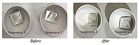
Figure 3.
Burn-off test of pGFRP specimen.
2.3. Static 4-Point Bending Tests
Quasi-static four-point flexural failure tests were performed following the guidelines of the ASTM D6272 standard to evaluate the flexural characteristics of the pGFRP laminates [36]. The test configuration, as shown in Figure 4, had a support span of 305 mm to ensure that failures only occurred in the outer fibres of the specimens, while the load span was 71 mm. The quasi-static load speed was set at 3.5 mm/min to ensure that the specimen would fail without exhibiting catastrophic behaviour (Figure 5). Then, using elastic beam theory [37], stresses and strains were estimated, as illustrated in Equations (1) and (2).
where is stress in the outer fibre in (Mpa), P is the load in (N), L is the support span in (mm), is the loading span in (mm), b is the specimen width in (mm), d is the specimen thickness in (mm), is the midspan deflection in (mm), and a is the distance from the support to the nearest loading point in (mm).
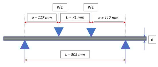
Figure 4.
Schematic diagram of the four-point bending experimental setup.
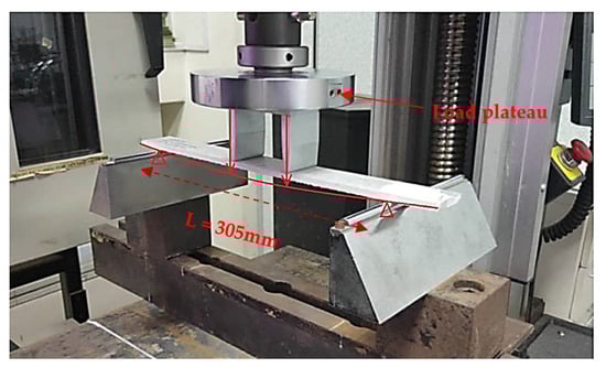
Figure 5.
The static four-point bending test.
2.4. Flexural Creep Test
The creep test arrangement was comparable to the ultimate flexural test system shown in Figure 4, with equivalent dimensions for loading and support spans. These tests followed the guidelines set by the ASTM D2990-17 standard [38]. Three load levels were set, namely 12%, 24%, and 37% of the ultimate flexural load. The experiments were conducted at room temperature for 720 h to allow creep to progress to the second stage. During the test, mid-span deflection was recorded immediately after loading, i.e., at time 0, and then every 15 min for the first 6 h. It was then taken every 24 h until the test was completed. The strain was determined using elastic beam theory after measuring the mid-span deflection with a dial gauge [37]. Figure 6 depicts a coupon specimen undergoing a creep test.
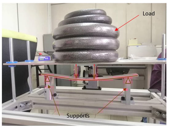
Figure 6.
A coupon sample under four-point bending creep test.
Later, Findley’s method was used to determine the time-dependent reduction factor, which in turn was used to estimate the drop in modulus of elasticity using the parameters n and m for each sequence. According to the original form of Findley’s power law, total strain consists of an elastic time-independent component and a viscous time-dependent component, as indicated in Equation (3).
where is the instantaneous elastic strain, t is the time under sustained load (hours), n and m are material-specific parameters.
3. Results and Discussions
3.1. Static Four-Point Bending Test Results
As previously discussed, short-term properties are important to determine the loads for the creep tests as they are taken as a percentage of the ultimate flexural strength. Three samples of each sequence were evaluated, with load versus deflection data displayed in Figure 7 and Figure 8, with horizontal lines denoting creep load levels. Meanwhile, Figure 7 and Figure 8 reveal that both stacking sequence specimens had a similar reaction, which, from the graph, exhibited linear elastic behaviour before failing due to brittleness. Table 2 summarises the stress and strain calculations. This behaviour is expected as GFRP laminates are not considered ductile materials, which is mainly attributed to the glass fibres in composites. For Sequence 1, the specimens had an average ultimate load of 1082 N with an average deflection at rupture of 66.6 mm, corresponding to an ultimate stress of 242.6 MPa and an ultimate strain of 0.02289 mm/mm. On the other hand, Sequence 2 exhibited a significantly higher strength where it recorded an average ultimate load of 2192 N with an average deflection at rupture of 57.7 mm, corresponding to an ultimate stress of 399.05 MPa and a strain at rupture of 0.02197 mm/mm.
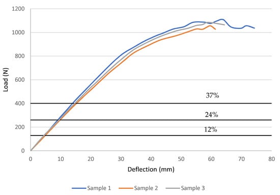
Figure 7.
Flexural load vs. deflection curves from the failure tests for Sequence 1.
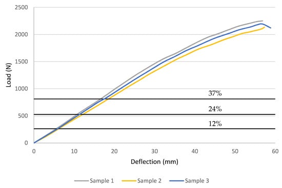
Figure 8.
Flexural load vs. deflection curves from the failure tests for Sequence 2.
Table 2.
Summary of the short-term material properties.
GFRP laminates show a clear dependency on fibre orientation and stacking sequences in their mechanical properties. In addition, damage and failure modes are influenced by the stacking sequence. However, symmetric and asymmetric stacking sequences displayed negligible differences [39,40,41].
3.2. Flexural Creep Results
The findings of the four-point flexural creep testing will be presented and discussed in this section. Table 3 shows the load levels and associated applied loads for each stacking sequence, which were calculated using the average ultimate flexural load obtained from static failure tests. Figure 9 and Figure 10 illustrate the midspan deflection as it rises over time for each load level for both stacking sequences. According to Figure 9, the primary stage of creep lasts longer with increasing load values, as described by Harries et al. [42]. Sequence 2, on the other hand, has higher flexural strength and flexural modulus than Sequence 1, which has a less pronounced trend, as seen in Figure 10.
Table 3.
Summary of the ultimate flexural load and creep load levels.
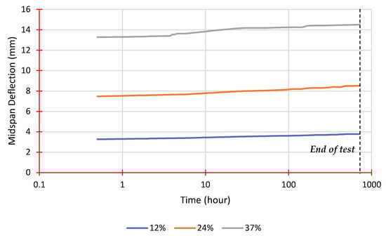
Figure 9.
Midspan deflection vs. time from creep tests for Sequence 1.
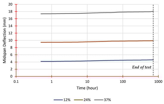
Figure 10.
Midspan deflection vs. time from creep tests for Sequence 2.
As previously discussed, other researchers have already shown the effects stacking sequences can have upon the mechanical properties of GFRP laminates [43,44]. As such, we expected creep performance to be affected. What these results illustrate are the significant differences between the two stacking sequences.
The difference in the primary stage of creep between both stacking sequences suggests that the higher fibre volume fraction of 69.04% in Sequence 2 may have contributed towards lowering its duration since it has less resin, which is considered the main contributor for creep in GFRP, especially in the primary stage [43]. This emphasises the importance of a greater fibre volume percentage in increasing the member’s strength, stiffness, and resistance to creep.
Findley’s power law, as illustrated in Equation (3), is used to examine creep behaviour in the primary and secondary stages. Findley’s model correctly describes the creep behaviour of FRP materials subjected to steady stress over an extended time range, while also being simple and straightforward to execute. The curve fits for both sequences at a 12% load level are shown in Figure 11, while Table 4 summarises all parameters derived from experimental data fittings.
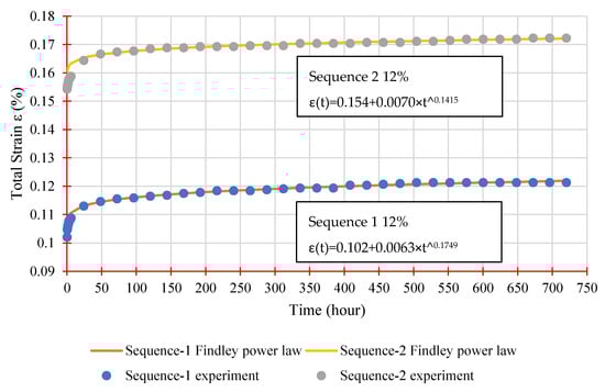
Figure 11.
Findley’s power law parameters evaluation.
Table 4.
Findley’s power law parameters, as obtained from experimental data fitting.
As shown in Table 4, parameter n remains nearly constant for each sequence regardless of stress level, averaging 0.1724 and 0.1353 for Sequence 1 and Sequence 2, respectively. This is to be expected, given that previous studies have demonstrated that n is stress independent. The m parameter, on the other hand, is stress-dependent and rises with increasing stress levels, with an average of 0.0114% for Sequence 1 and 0.0084% for Sequence 2. Furthermore, both metrics, 0.12–0.35 for n and 0.0061–0.0184% for m, are within the ranges reported by other studies using similar stress levels. A generic Findley’s equation may be expressed below by taking the average value of n and m for each series.
Equations (4) and (5) are plotted in Figure 12 and Figure 13 with the instantaneous elastic strain taken from the experimental tests. These equations are very closely matched with the measured data confirming the efficaciousness of Findley’s power law to simulate the creep behaviour of GFRP laminates.
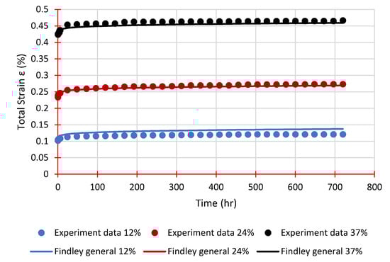
Figure 12.
Experimental strains and Findley’s general equation for Sequence 1.
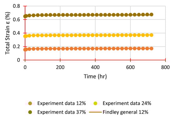
Figure 13.
Experimental strains and Findley’s general equation for Sequence 2.
For the verification of the serviceability limit state, specifically long-term deformation, it is useful to obtain a reduced modulus of elasticity to be used in manual calculations or in an analysis program. Noting that and , Equation (3) can be rewritten in the following form:
From Equation (6), the time-dependent flexural modulus can be obtained as follows:
Following a similar approach to Scott and Zureick [44], Equation (7) can be rearranged to have a time-dependent reduction factor χ(t).
Equation (7) calculates the projected reduction in flexural modulus. Table 5 shows the flexural modulus for each sequence, determined using Equations (8) and (9) to calculate the expected reduction factors over numerous years. A significant variation between the two sequences is apparent, with Sequence 1 losing 23% of its rigidity and Sequence 2 losing only 10%. This highlights the importance of testing samples from a specific manufacturer to get tangible results, enabling more accurate modelling for GFRP laminates in the analysis and design stages. Moreover, one month of creep testing seems to be sufficient in providing creep material parameters via Findley’s power law as long as the stress level is not too high, to stay within the secondary stage of creep. Figure 14 shows the reduction factor over time in a graphical plot.
Table 5.
Predicted reduction factor and flexural modulus for each sequence.
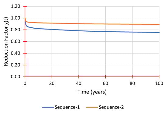
Figure 14.
Reduction factor χ(t) prediction over time.
The results in Table 5 and Figure 14 show large discrepancies between different fibre stacking sequences that can be found in pGFRP cross arms and how sensitive the material characteristics and parameters are. On the other hand, it is clear that 90% of the initial flexural stiffness can be maintained over 50 years which is evidently influenced by the stacking sequence of pGFRP laminate.
4. Conclusions
An experimental investigation of the flexural creep behaviour of glass fibre reinforced polymer laminates made by pultrusion is discussed in this study. Two different sequences were used to highlight the differences in the material properties’ creep behaviour. The short-term and long-term tests had the same four-point bending configuration and dimensions.
In addition, analytical modelling using Findley’s power law was also conducted and presented. The reduction factor χ(t) and, ultimately, the time-dependent modulus E(t), were calculated using Findley’s parameters. This work came to the following conclusions:
The differences in short-term properties between the sequences were significant, especially with regards to the ultimate strength of 242.6 MPa for Sequence 1 and 399.05 MPa for Sequence 2, which reflects the fibre arrangement and manufacturing quality despite both using the same manufacturing technique.
Sequence 1 showed a clear increase in the duration of the primary creep stage with higher loads, unlike Sequence 2 which did not exhibit a clear trend. This emphasizes the importance of choosing an appropriate length for creep tests, including to use of an additional second stage.
The creep behaviour was modelled successfully using Findley’s power law, proving the reliability of this approach to simulate the viscoelastic response of pGFRP laminates. As expected, the n parameter was almost constant across different stress levels for each sequence, while the m parameter increased with the higher loads. Moreover, a general Findley equation was successfully developed for each sequence which provided accurate predictions for strains when compared to the experimental data.
The time-dependent reduction factor χ(t) was calculated at different time intervals for both sequences to predict the reduced flexural modulus. Sequence 1 showed a 23% reduction after 50 years, noticeably different compared to Sequence 2, which was expected to lose about 10%. These results proved that the stacking implemented sequences have an effect on pGFRP material properties and creep performance.
Author Contributions
Conceptualization, A.A. and A.S.; methodology, A.A. and A.S.; software, A.A.; validation, M.R.M.A., M.A.A. and F.U.; formal analysis, A.A. and A.S.; investigation, A.B.M.S. and M.R.M.A.; resources, A.S., F.U. and A.A.; writing—original draft preparation, A.A. and A.B.M.S.; writing—review and editing, A.A., A.B.M.S. and M.R.M.A.; visualization, A.B.M.S., M.R.M.A. and F.U.; supervision, A.S., F.U. and A.B.M.S.; project administration, A.S., F.U. and M.A.A.; funding acquisition, A.S. All authors have read and agreed to the published version of the manuscript.
Funding
This research was funded by IRMC UNITEN grant number J510050002-IC-6 BOLDREFRESH2025-CENTRE OF EXCELLENCE. The APC was funded by IRMC UNITEN.
Institutional Review Board Statement
Not applicable.
Informed Consent Statement
Not applicable.
Data Availability Statement
Not applicable.
Acknowledgments
The authors are grateful to acknowledge the IRMC UNITEN and the Institute of Energy Infrastructure (IEI) for the lab facilities and financial support provided through Bold 2021 research grant.
Conflicts of Interest
The authors declare no conflict of interest.
References
- Amir, A.L.; Ishak, M.R.; Yidris, N.; Zuhri, M.Y.M.; Asyraf, M.R.M. Advances of composite cross arms with incorporation of material core structures: Manufacturability, recent progress and views. J. Mater. Res. Technol. 2021, 13, 1115–1131. [Google Scholar] [CrossRef]
- Bakar, M.S.A.; Mohamad, D.; Ishak, Z.A.M.; Yusof, Z.M.; Salwi, N. Durability control of moisture degradation in GFRP cross arm transmission line towers. AIP Conf. Proc. 2018, 2031, 020027. [Google Scholar] [CrossRef]
- Sharaf, H.K.; Ishak, M.R.; Sapuan, S.M.; Yidris, N. Conceptual design of the cross-arm for the application in the transmission towers by using TRIZ–morphological chart–ANP methods. J. Mater. Res. Technol. 2020, 9, 9182–9188. [Google Scholar] [CrossRef]
- Selvaraj, M.; Kulkarni, S.; Babu, R.R. Analysis and experimental testing of a built-up composite cross arm in a transmission line tower for mechanical performance. Compos. Struct. 2013, 96, 1–7. [Google Scholar] [CrossRef]
- Alipour, H.J.; Aminnejad, S.; Jazaeri, M. Decreasing the right of way of transmission lines by using towers with polymer insulation arms. In Proceedings of the International Conference on Power Engineering, Energy and Electrical Drives, POWERENG, Setubal, Portugal, 12–14 April 2007; pp. 571–576. [Google Scholar] [CrossRef]
- Aboudi, J.; Al Azzawi, W.; Alampalli, S.; Aniskevich, A.; Barbero, E.J.; Beyle, A.; Bhuiyan, F.H.; Epaarachchi, J.; Fertig, R.S.; Glaskova-Kuzmina, T.; et al. Creep and Fatigue in Polymer Matrix Composites, 2nd ed.; Elsevier: Amsterdam, The Netherlands, 2019. [Google Scholar] [CrossRef]
- Findley, W.N. 26-Year creep and recovery of poly(vinyl chloride) and polyethylene. Polym. Eng. Sci. 1987, 27, 582–585. [Google Scholar] [CrossRef]
- Sá, M.F.; Gomes, A.M.; Correia, J.R.; Silvestre, N. Creep behavior of pultruded GFRP elements—Part 2: Analytical study. Compos. Struct. 2011, 93, 2409–2418. [Google Scholar] [CrossRef]
- Jayaprakash, K.; Desai, Y.M.; Naik, N.K. Fatigue behavior of [0n/90n]s composite cantilever beam under tip impulse loading. Compos. Struct. 2013, 99, 255–263. [Google Scholar] [CrossRef]
- Ascione, L.; Berardi, V.P.; D’Aponte, A. Creep phenomena in FRP materials. Mech. Res. Commun. 2012, 43, 15–21. [Google Scholar] [CrossRef]
- Sá, M.F.; Gomes, A.M.; Correia, J.R.; Silvestre, N. Creep behavior of pultruded GFRP elements—Part 1: Literature review and experimental study. Compos. Struct. 2011, 93, 2450–2459. [Google Scholar] [CrossRef]
- Muliana, A.H.; Haj-Ali, R.M. Analysis for creep behavior and collapse of thick-section composite structures. Compos. Struct. 2006, 73, 331–341. [Google Scholar] [CrossRef]
- Johari, A.N.; Ishak, M.R.; Leman, Z.; Yusoff, M.Z.M.; Asyraf, M.R.M. Influence of CaCO3 in pultruded glass fiber/unsaturated polyester resin composite on flexural creep behavior using conventional and time-temperature superposition principle methods. Polimery 2020, 65, 792–800. [Google Scholar] [CrossRef]
- Mallick, P.K. Fibre-Reinforced Composites Materials, Manufacturing and Design; CRC Press: Boca Raton, FL, USA, 2007; Volume 20. [Google Scholar] [CrossRef]
- Sá, M.F.; Gomes, A.M.; Correia, J.R.; Silvestre, N. Flexural creep response of pultruded GFRP deck panels: Proposal for obtaining full-section viscoelastic moduli and creep coefficients. Compos. Part B Eng. 2016, 98, 213–224. [Google Scholar] [CrossRef]
- Li, X.; Liu, W.; Fang, H.; Huo, R.; Wu, P. Flexural creep behavior and life prediction of GFRP-balsa sandwich beams. Compos. Struct. 2019, 224, 111009. [Google Scholar] [CrossRef]
- Bottoni, M.; Mazzotti, C.; Savoia, M. Creep tests on GFRP pultruded specimens subjected to traction or shear. Compos. Struct. 2014, 108, 514–523. [Google Scholar] [CrossRef]
- US Department of Defense. Composite Materials Handbook Volume 1: Polymer Matrix Composites-Guidelines for Characterisation of Structural Materials. Compos. Mater. Handb. Ser. 2002, 1, 1–586. [Google Scholar]
- Patel, P.; Chokshi, S. A Review of Fabrication Methods and Stacking Sequence Arrangements of Fiber for Composite. Int. J. Curr. Eng. Sci. Res. 2018, 5, 13–20. [Google Scholar]
- Beloshenko, V.; Voznyak, Y.; Voznyak, A.; Savchenko, B. New approach to production of fiber reinforced polymer hybrid composites. Compos. Part B Eng. 2017, 112, 22–30. [Google Scholar] [CrossRef]
- Mohamad, D.; Syamsir, A.; Beddu, S.; Kamal NL, M.; Zainoodin, M.M.; Razali, M.F. Effect of Laminate Properties on the Failure of Cross Arm Structure under Multi-Axial Load. IOP Conf. Ser. Mater. Sci. Eng. 2019, 530, 12029. [Google Scholar] [CrossRef]
- Asyraf, M.R.M.; Ishak, M.R.; Sapuan, S.M.; Yidris, N.; Ilyas, R.A. Woods and composites cantilever beam: A comprehensive review of experimental and numerical creep methodologies. J. Mater. Res. Technol. 2020, 9, 6759–6776. [Google Scholar] [CrossRef]
- Lu, T.; Solis-Ramos, E.; Yi, Y.; Kumosa, M. UV degradation model for polymers and polymer matrix composites. Polym. Degrad. Stab. 2018, 154, 203–210. [Google Scholar] [CrossRef]
- Kobelev, V. Some basic solutions for nonlinear creep. Int. J. Solids. Struct. 2014, 51, 3372–3381. [Google Scholar] [CrossRef] [Green Version]
- Beddu, S.; Syamsir, A.; Ishak, Z.A.M.; Yusof, Z.M.; Hudi, N.S.; Nabihah, S. Creep behavior of glass fibre reinforced polymer structures in crossarms transmission line towers. AIP Conf. Proc. 2018, 2031, 020039. [Google Scholar] [CrossRef]
- Othman, A.; Abdullah, S.; Ariffin, A.K.; Mohamed, N.A.N. Investigating the quasi-static axial crushing behavior of polymeric foam-filled composite pultrusion square tubes. J. Mater. 2014, 63, 446–459. [Google Scholar] [CrossRef]
- Abu Bakar, M.S.; Salit, M.S.; Mohamad Yusoff, M.Z.; Zainudin, E.S.; Ya, H.H. The crashworthiness performance of stacking sequence on filament wound hybrid composite energy absorption tube subjected to quasi-static compression load. J. Mater. Res. Technol. 2020, 9, 654–666. [Google Scholar] [CrossRef]
- Mohamad, D.; Syamsir, A.; Sa’Don, S.N.; Zahari, N.M.; Seman, S.A.H.A.; Razali, M.F.; Ng, F.C.; Abas, A. Stacking Sequence Effects on Performance of Composite Laminate Structure Subjected to Multi-Axial Quasi-Static Loading. IOP Conf. Ser. Mater. Sci. Eng. 2019, 530, 012030. [Google Scholar] [CrossRef]
- Supian, A.B.M.; Sapuan, S.M.; Zuhri, M.Y.M.; Zainudin, E.S.; Ya, H.H.; Hisham, H.N. Effect of winding orientation on energy absorption and failure modes of filament wound kenaf/glass fibre reinforced epoxy hybrid composite tubes under intermediate-velocity impact (IVI) load. J. Mater. Res. Technol. 2021, 10, 1–14. [Google Scholar] [CrossRef]
- Guades, E.; Aravinthan, T. Residual properties of square FRP composite tubes subjected to repeated axial impact. Compos. Struct. 2013, 95, 354–365. [Google Scholar] [CrossRef]
- Hao, A.; Chen, Y.; Chen, J.Y. Creep and recovery behavior of kenaf/polypropylene nonwoven composites. J. Appl. Polym. Sci. 2014, 131, 8864–8874. [Google Scholar] [CrossRef]
- Choi, Y.; Yuan, R.L. Time-Dependent Deformation of Pultruded Fiber Reinforced Polymer Composite Columns. J. Compos. Constr. 2003, 7, 356–362. [Google Scholar] [CrossRef]
- Mottram, J.T. Short- and long-term structural properties of pultruded beam assemblies fabricated using adhesive bonding. Compos. Struct. 1993, 25, 387–395. [Google Scholar] [CrossRef]
- ASTM Standard D2584; Standard Test Method for Ignition Loss of Cured Reinforced Resin. ASTM: West Conshohocken, PA, USA, 2011; pp. 1–3. [CrossRef]
- Saba, N.; Paridah, M.T.; Jawaid, M. Mechanical properties of kenaf fibre reinforced polymer composite: A review. Constr. Build. Mater. 2015, 76, 87–96. [Google Scholar] [CrossRef]
- ASTM Standard D6272-17; Standard Test Method for Flexural Properties of Unreinforced and Reinforced Plastics and Electrical Insulating Materials by Four-Point Bending. ASTM: West Conshohocken, PA, USA, 2017; pp. 1–9. [CrossRef]
- Hibbeler, R. Structural Analysis, 9th ed.; Pearson: London, UK, 2015. [Google Scholar]
- ASTM Standard D2990-17; Standard Test Methods for Tensile, Compressive, and Flexural Creep and Creep- Rupture of Plastics. ASTM: West Conshohocken, PA, USA, 2017; pp. 1–21. [CrossRef]
- Asyraf, M.R.M.; Ishak, M.R.; Sapuan, S.M.; Yidris, N. Utilization of bracing arms as additional reinforcement in pultruded glass fiber-reinforced polymer composite cross-arms: Creep experimental and numerical analyses. Polymers 2021, 13, 620. [Google Scholar] [CrossRef] [PubMed]
- Shrivastava, R.; Singh, K.K.; Modi, V. Effect of Stacking Sequence on Interlaminar Shear Strength of Multidirectional GFRP Laminates. Mater. Today Proc. 2020, 22, 2207–2214. [Google Scholar] [CrossRef]
- Podolak, P.; Droździel, M.; Czapski, P.; Kubiak, T.; Bieniaś, J. The failure mode variation in post-buckled GFRP columns with different stacking sequences-Experimental damage analysis and numerical prediction. Int. J. Mech. Sci. 2021, 210, 106747. [Google Scholar] [CrossRef]
- Harries, K.A.; Guo, Q.; Cardoso, D. Creep and creep buckling of pultruded glass-reinforced polymer members. Compos. Struct. 2017, 181, 315–324. [Google Scholar] [CrossRef]
- Berardi, V.P.; Perrella, M.; Feo, L.; Cricrì, G. Creep behavior of GFRP laminates and their phases: Experimental investigation and analytical modeling. Compos. Part B Eng. 2017, 122, 136–144. [Google Scholar] [CrossRef]
- Scott, D.W.; Zureick, A.-H. Compression creep of a pultruded E-glass/vinylester composite. Compos. Sci. Technol. 1998, 58, 1361–1369. [Google Scholar] [CrossRef]


Publisher’s Note: MDPI stays neutral with regard to jurisdictional claims in published maps and institutional affiliations. |
© 2022 by the authors. Licensee MDPI, Basel, Switzerland. This article is an open access article distributed under the terms and conditions of the Creative Commons Attribution (CC BY) license (https://creativecommons.org/licenses/by/4.0/).