
Effect of High-Entropy Spinel Ferrite (Mn0.2Zr0.2Cu0.2Ca0.2Ni0.2)Fe2O4 Doping Concentration on the Ferroelectric Properties of PVDF-Based Polymers
Abstract
:1. Introduction
2. Materials and Methods
2.1. Materials
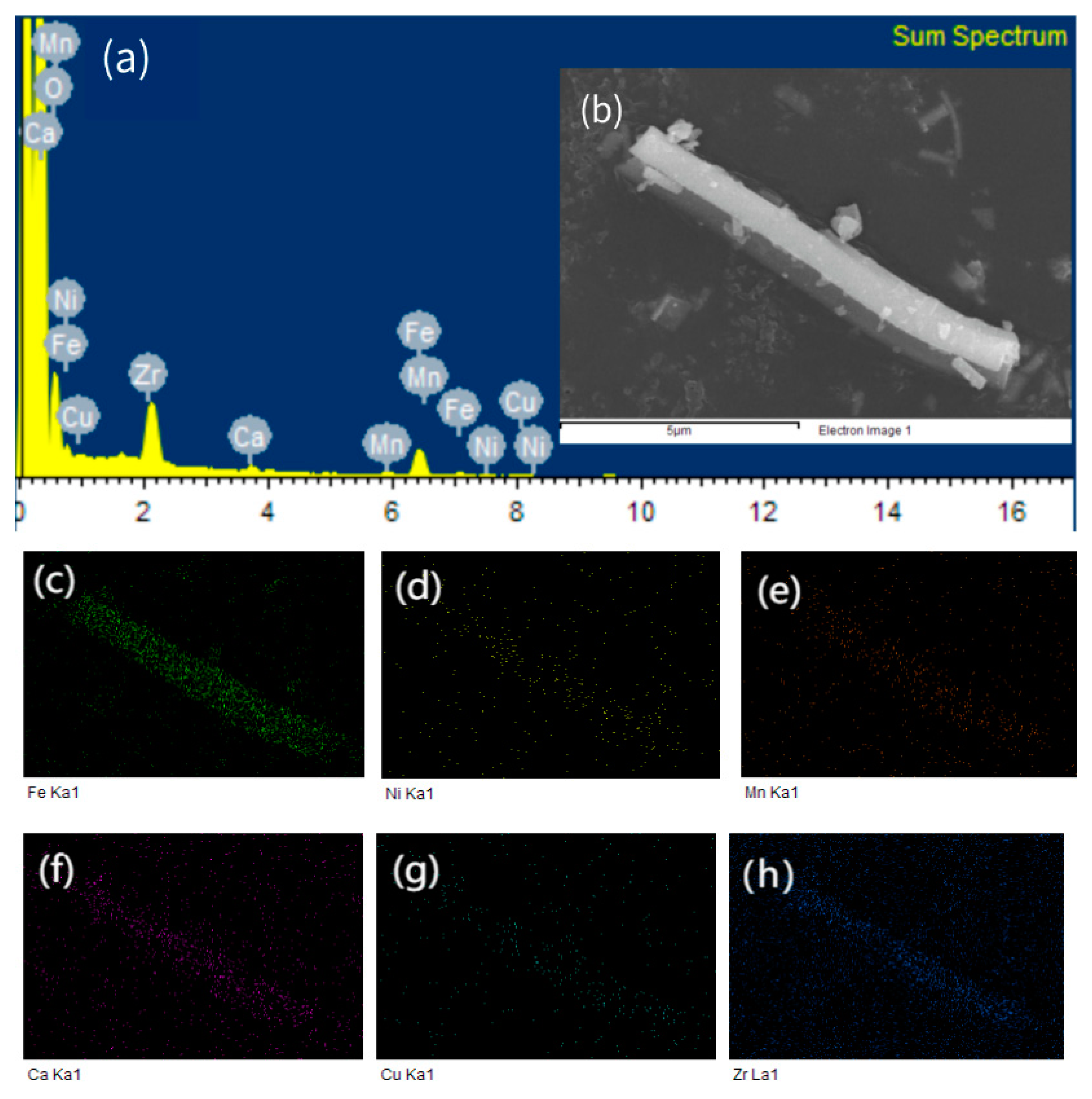
2.2. Synthesis of High-Entropy Spinel Ferrite (Mn0.2Zr0.2Cu0.2Ca0.2Ni0.2)Fe2O4 NFs
2.3. Fabrication of (Mn0.2Zr0.2Cu0.2Ca0.2Ni0.2)Fe2O4/PVDF Nanocomposite Film
2.4. Characterization
3. Results and Discussion
4. Conclusions
Author Contributions
Funding
Institutional Review Board Statement
Data Availability Statement
Conflicts of Interest
References
- Wang, J.-J.; Su, Y.-J.; Wang, B.; Ouyang, J.; Ren, Y.-H.; Chen, L.-Q. Strain engineering of dischargeable energy density of ferroelectric thin-film capacitors. Nano Energy 2020, 72, 104665. [Google Scholar] [CrossRef]
- Shen, Z.-H.; Bao, Z.-W.; Cheng, X.-X.; Li, B.-W.; Liu, H.-X.; Shen, Y.; Chen, L.-Q.; Li, X.-G.; Nan, C.-W. Designing polymer nanocomposites with high energy density using machine learning. NPJ Comput. Mater. 2021, 7, 110. [Google Scholar] [CrossRef]
- Li, Q.; Chen, L.; Gadinski, M.R.; Zhang, S.; Zhang, G.; Li, H.U.; Iagodkine, E.; Haque, A.; Chen, L.-Q.; Jackson, T.N.; et al. Flexible high-temperature dielectric materials from polymer nanocomposites. Nature 2015, 523, 576–579. [Google Scholar] [CrossRef]
- Ren, X.; Meng, N.; Zhang, H.; Wu, J.; Abrahams, I.; Yan, H.; Bilotti, E.; Reece, M.J. Giant energy storage density in PVDF with internal stress engineered polar nanostructures. Nano Energy 2020, 72, 104662. [Google Scholar] [CrossRef]
- Diao, C.; Wang, H.; Wang, B.; He, Y.; Hou, Y.; Zheng, H. Overviews of dielectric energy storage materials and methods to improve energy storage density. J. Mater. Sci. Mater. Electron. 2022, 33, 21199–21222. [Google Scholar] [CrossRef]
- Evangeline, T.G.; Annamalai, A.R.; Ctibor, P. Effect of Europium Addition on the Microstructure and Dielectric Properties of CCTO Ceramic Prepared Using Conventional and Microwave Sintering. Molecules 2023, 28, 1649. [Google Scholar] [CrossRef]
- Djafar, R.; Boumchedda, K.; Fasquelle, D.; Chaouchi, A.; Sedda, K.; Bououdina, M.; Bellucci, S.; Bánhegyi, G. Dielectric properties of nanocrystalline CaCu3Ti4O12 (CCTO) ceramics fabricated from Algerian limestone raw material. Mater. Chem. Phys. 2023, 301, 127558. [Google Scholar] [CrossRef]
- Shirsath, S.E.; Assadi, M.H.N.; Zhang, J.; Kumar, N.; Gaikwad, A.S.; Yang, J.; Maynard-Casely, H.E.; Tay, Y.Y.; Du, J.; Wang, H.; et al. Interface-Driven Multiferroicity in Cubic BaTiO3-SrTiO3 Nanocomposites. ACS Nano 2022, 16, 15413–15424. [Google Scholar] [CrossRef]
- Habib, M.; Zhou, X.; Tang, L.; Xue, G.; Akram, F.; Alzaid, M.; Zhang, D. Phase and domain engineering strategy for enhancement of piezoelectricity in the lead-free BiFeO3-BaTiO3 ceramics. J. Materiomics 2023. [Google Scholar] [CrossRef]
- Alkathy, M.; Rahaman, A.; Mastelaro, V.R.; Zabotto, F.; Milton, F.P.; Eiras, J. Achieving high energy storage density simultaneously with large efficiency and excellent thermal stability by defect dipole, and microstructural engineering in modified-BaTiO3 ceramics. J. Alloys Compd. 2023, 934, 167887. [Google Scholar] [CrossRef]
- Zhou, L.; Jiang, M.; Sun, Y.; Yang, D.; Xu, J.; Peng, Z.; Wu, D.; Wei, L.; Liang, P.; Chao, X.; et al. Good temperature stability and colossal permittivity in TiO2 ceramics doped with Cu2+ and W6+ ions. Ceram. Int. 2023, 49, 11705–11710. [Google Scholar] [CrossRef]
- Hsu, T.H.; Huang, C.L. Microwave dielectric properties of ultra-low-temperature-sintered TiO2 as a τ f compensator. Appl. Phys. A 2023, 129, 20. [Google Scholar] [CrossRef]
- Liu, Y.; Liu, W.; Zhou, Y.; Chen, J.; Wang, Z.; Du, W.; Wen, J.; Cao, J.; Zhang, D. Enhanced di-electric constant and breakdown strength in dielectric composites using TiO2@HfO2 nanowires with gradient dielectric constant. Ceram. Int. 2022, 48, 12483–12489. [Google Scholar] [CrossRef]
- Liu, L.; Liu, Y.; Hao, J.; Chen, J.; Li, P.; Chen, S.; Fu, P.; Li, W.; Zhai, J. Multi-scale collaborative optimization of SrTiO3-based energy storage ceramics with high performance and excellent stability. Nano Energy 2023, 109, 108275. [Google Scholar] [CrossRef]
- Yan, Y.; Zeng, X.; Deng, T.; Chen, F.; Yang, L.; He, Z.; Jin, L.; Liu, G. Rheological, mechanical, and electrical properties of Sr0.7Bi0.2TiO3 modified BaTiO3 ceramic and its composites. J. Am. Ceram. Soc. 2023, 106, 3052–3065. [Google Scholar] [CrossRef]
- Yan, F.; Bai, H.; Ge, G.; Lin, J.; Shi, C.; Zhu, K.; Shen, B.; Zhai, J.; Zhang, S. Composition and Structure Optimized BiFeO3-SrTiO3 Lead-Free Ceramics with Ultrahigh Energy Storage Performance. Small 2022, 18, e2106515. [Google Scholar] [CrossRef] [PubMed]
- Rahman, S.; Hussain, A.; Noreen, S.; Bibi, N.; Arshad, S.; Rehman, J.U.; Tahir, M.B. Structural, electronic, optical and mechanical properties of oxide-based perovskite ABO3 (A=Cu, Nd and B=Sn, Sc): A DFT study. J. Solid State Chem. 2023, 317, 123650. [Google Scholar] [CrossRef]
- Karlinskii, B.Y.; Ananikov, V.P. Recent advances in the development of green furan ring-containing polymeric materials based on renewable plant biomass. Chem. Soc. Rev. 2023, 52, 836–862. [Google Scholar] [CrossRef] [PubMed]
- Wang, D.; Li, T. Toward MOF@Polymer Core–Shell Particles: Design Principles and Potential Applications. Acc. Chem. Res. 2023, 56, 462–474. [Google Scholar] [CrossRef] [PubMed]
- Veved, A.; Ejuh, G.W.; Djongyang, N. Review of emerging materials for PVDF-based energy harvesting. Energy Rep. 2022, 8, 12853–12870. [Google Scholar] [CrossRef]
- Xu, H.; He, G.; Chen, S.; Chen, S.; Qiao, R.; Luo, H.; Zhang, D. All-organic polymer dielectrics containing sulfonyl dipolar groups and π– π stacking interaction in side-chain architectures. Macromolecules 2021, 54, 8195–8206. [Google Scholar] [CrossRef]
- Luo, H.; Zhou, X.; Ellingford, C.; Zhang, Y.; Chen, S.; Zhou, K.; Zhang, D.; Bowen, C.R.; Wan, C. Interface design for high energy density polymer nanocomposites. Chem. Soc. Rev. 2019, 48, 4424–4465. [Google Scholar] [CrossRef] [PubMed] [Green Version]
- Rabuffi, M.; Picci, G. Status quo and future prospects for metallized polypropylene energy storage capacitors. IEEE Trans. Plasma Sci. 2002, 30, 1939–1942. [Google Scholar] [CrossRef]
- Yi, Z.; Wang, Z.; Li, Y.; Wu, D.; Xue, Y. Improving the Energy Storage Performance of All-Polymer Composites by Blending PVDF and P(VDF−CTFE). Macromol. Rapid Commun. 2023, 44. [Google Scholar] [CrossRef] [PubMed]
- Dohany, J.E. Fluorine-containing polymers, poly (vinylidene fluoride). In Kirk-Othmer Encyclopedia of Chemical Technology; Wiley: Hoboken, NJ, USA, 2000. [Google Scholar] [CrossRef]
- Liu, F.; Hashim, N.A.; Liu, Y.; Moghareh Abed, M.R.; Li, K. Progress in the production and modification of PVDF membranes. J. Membr. Sci. 2011, 375, 1–27. [Google Scholar] [CrossRef]
- Prest, W.M.; Luca, D.J. The formation of the γ phase from the α and β polymorphs of polyvinylidene fluoride. J. Appl. Phys. 1978, 49, 5042–5047. [Google Scholar] [CrossRef]
- Ramos, M.M.; Correia, H.M.; Lanceros-Méndez, S. Atomistic modelling of processes involved in poling of PVDF. Comput. Mater. Sci. 2005, 33, 230–236. [Google Scholar] [CrossRef] [Green Version]
- Lovinger, A.J. Developments in Crystalline Polymers—L; Springer Nature: Berlin/Heidelberg, Germany, 1982; Volume 33. [Google Scholar] [CrossRef]
- Zhang, B.; Chen, X.-M.; Wu, W.-W.; Khesro, A.; Liu, P.; Mao, M.; Song, K.; Sun, R.; Wang, D. Outstanding discharge energy density and efficiency of the bilayer nanocomposite films with BaTiO3-dispersed PVDF polymer and polyetherimide layer. Chem. Eng. J. 2022, 446, 136926. [Google Scholar] [CrossRef]
- Garg, T.; Dabra, N.; Hundal, J.S. Dielectric Switching and Ferroelectric Studies of α, γ PVDF Phases for Energy Storage Properties. Integr. Ferroelectr. 2023, 231, 142–152. [Google Scholar] [CrossRef]
- Wang, T.; Peng, R.-C.; Dong, G.; Du, Y.; Zhao, S.; Zhao, Y.; Zhou, C.; Yang, S.; Shi, K.; Zhou, Z.; et al. Enhanced Energy Density at a Low Electric Field in PVDF-Based Heterojunctions Sandwiched with High Ion-Polarized BTO Films. ACS Appl. Mater. Interfaces 2022, 14, 17849–17857. [Google Scholar] [CrossRef]
- Kaur, S.; Singh, D.P. Significantly improved dielectric and energy storage behavior of the surface functionalized CaCu3Ti4O12 nanoparticles in PVDF-CaCu3Ti4O12 nanocomposites. J. Alloys Compd. 2022, 918, 165500. [Google Scholar] [CrossRef]
- Tang, T.; Yang, W.; Shen, Z.; Wang, J.; Guo, M.; Xiao, Y.; Ren, W.; Ma, J.; Yu, R.; Nan, C.; et al. Compressible Polymer Composites with Enhanced Dielectric Temperature Stability. Adv. Mater. 2023, 35, e2209958. [Google Scholar] [CrossRef]
- Hou, D.; Zhou, J.; Chen, W.; Zhang, P.; Shen, J.; Jian, Z. Core@double-shell structured fillers for increasing dielectric constant and suppressing dielectric loss of PVDF-based composite films. Ceram. Int. 2022, 48, 22691–22698. [Google Scholar] [CrossRef]
- Wang, H.-Q.; Wang, J.-W.; Wang, X.-Z.; Gao, X.-H.; Zhuang, G.-C.; Yang, J.-B.; Ren, H. Dielectric properties and energy storage performance of PVDF-based composites with MoS2@MXene nanofiller. Chem. Eng. J. 2022, 437, 135431. [Google Scholar] [CrossRef]
- Guo, Y.; Liu, S.; Wu, S.; Xu, J.; Pawlikowska, E.; Bulejak, W.; Szafran, M.; Rydosz, A.; Gao, F. Enhanced tunable dielectric properties of Ba0.6Sr0.4TiO3/PVDF composites through dual-gradient structural engineering. J. Alloys Compd. 2022, 920, 166034. [Google Scholar] [CrossRef]
- Luo, H.-B.; Pan, X.-R.; Yang, J.-H.; Qi, X.-D.; Wang, Y. Simultaneously Improved Dielectric Constant and Breakdown Strength of PVDF-based Composites with Polypyrrole Nanowire Encapsuled Molybdenum Disulfide Nanosheets. Chin. J. Polym. Sci. 2022, 40, 515–525. [Google Scholar] [CrossRef]
- Zhou, J.; Zhou, W.; Cao, D.; Zhang, C.; Peng, W.; Yao, T.; Zuo, J.; Cai, J.; Li, Y. PVDF reinforced with core–shell structured Mo@MoO3 fillers: Effects of semi-conductor MoO3 interlayer on dielectric properties of composites. J. Polym. Res. 2022, 29, 72. [Google Scholar] [CrossRef]
- Sang, X.; Li, X.; Zhang, D.; Zhang, X.; Wang, H.; Li, S. Improved dielectric properties and energy-storage densities of BaTiO3-doped PVDF composites by heat treatment and surface modification of BaTiO3. J. Phys. D Appl. Phys. 2022, 55, 215501. [Google Scholar] [CrossRef]
- Tan, Y.; Hou, Y.; Lin, Q.; Zhen, Y.; Du, P.; Luo, L.; Li, W. Remarkably Enhanced Energy Storage Performances in Well-Designed Core–Shell Ag@TiO2–Poly (vinylidene fluoride) Nanocomposites. ACS Appl. Polym. Mater. 2022, 4, 7417–7425. [Google Scholar] [CrossRef]
- Rao, Z.; Tung, P.-Y.; Xie, R.; Wei, Y.; Zhang, H.; Ferrari, A.; Klaver, T.; Körmann, F.; Sukumar, P.T.; da Silva, A.K.; et al. Machine learning–enabled high-entropy alloy discovery. Science 2022, 378, 78–85. [Google Scholar] [CrossRef]
- Jiang, B.; Yu, Y.; Cui, J.; Liu, X.; Xie, L.; Liao, J.; Zhang, Q.; Huang, Y.; Ning, S.; Jia, B.; et al. High-entropy-stabilized chalcogenides with high thermoelectric performance. Science 2021, 371, 830–834. [Google Scholar] [CrossRef]
- Wang, K.; Chen, L.; Xu, C.; Zhang, W.; Liu, Z.; Wang, Y.; Ouyang, J.; Zhang, X.; Fu, Y.; Zhou, Y. Microstructure and mechanical properties of (TiZrNbTaMo)C high-entropy ceramic. J. Mater. Sci. Technol. 2020, 39, 99–105. [Google Scholar] [CrossRef]
- Pu, Y.; Zhang, Q.; Li, R.; Chen, M.; Du, X.; Zhou, S. Dielectric Properties and Electrocaloric Effect of High-Entropy (Na0.2bi0.2ba0.2sr0.2ca0.2)TiO3 Ceramic. Appl. Phys. Lett. 2019, 115, 223901. [Google Scholar] [CrossRef]
- Liu, J.; Ren, K.; Ma, C.; Du, H.; Wang, Y. Dielectric and energy storage properties of flash- sintered high-entropy (Bi0.2Na0.2K0.2Ba0.2Ca0.2)TiO3 ceramic. Ceram. Int. 2020, 46, 20576–20581. [Google Scholar] [CrossRef]
- Chen, L.; Deng, S.; Liu, H.; Wu, J.; Qi, H.; Chen, J. Giant energy-storage density with ultrahigh efficiency in lead-free relaxors via high-entropy design. Nat. Commun. 2022, 13, 3089. [Google Scholar] [CrossRef] [PubMed]
- Yang, B.; Zhang, Y.; Pan, H.; Si, W.; Zhang, Q.; Shen, Z.; Yu, Y.; Lan, S.; Meng, F.; Liu, Y.; et al. High-entropy enhanced capacitive energy storage. Nat. Mater. 2022, 21, 1074–1080. [Google Scholar] [CrossRef] [PubMed]
- Wang, R.; Gou, B.; Fu, J.; Xu, H.; Cheng, S.; Zhou, J.; Zhu, Y.; He, J.; Xie, C.; Li, Q. High-energy-density ferroelectric polymer nanocomposites utilizing the Coulomb-blockade effect. Mater. Today Nano 2022, 20. [Google Scholar] [CrossRef]
- Prateek, V.K.T.; Gupta, R.K. Recent progress on ferroelectric polymer-based nanocomposites for high energy density capacitors: Synthesis, dielectric properties, and future aspects. Chem. Rev. 2016, 116, 4260–4317. [Google Scholar] [CrossRef]
- Heiba, Z.K.; Mohamed, M.B.; Ghannam, M.M.; Ahmed, S.I. Influence of iron substitution on structural and dielectric properties of nano ZnMn2O4. Appl. Phys. A 2021, 127, 436. [Google Scholar] [CrossRef]
- Behera, C.; Choudhary, R.N.P.; Das, P.R. Development of Ni-Ferrite-Based PVDF Nanomultiferroics. J. Electron. Mater. 2017, 46, 6009–6022. [Google Scholar] [CrossRef]
- Jurczuk, K.; Galeski, A.; Mackey, M.; Hiltner, A.; Baer, E. Orientation of PVDF α and γ crystals in nanolayered films. Colloid Polym. Sci. 2015, 293, 1289–1297. [Google Scholar] [CrossRef] [PubMed] [Green Version]
- Yuan, M.; Wang, H.; Wang, T.; Yang, H.; Yuan, C. Synergistic Improvement in γ-Phase Content and Dielectric Properties of PVDF/Deep Eutectic Solvent/Montmorillonite Composite Films. ACS Appl. Polym. Mater. 2023, 5, 2664–2673. [Google Scholar] [CrossRef]


| Components | Mass % |
|---|---|
| Fe2O3 | 65.0138 |
| MnO | 5.9912 |
| CaO | 4.8054 |
| NiO | 5.7665 |
| CuO | 6.5011 |
| ZrO2 | 11.3498 |
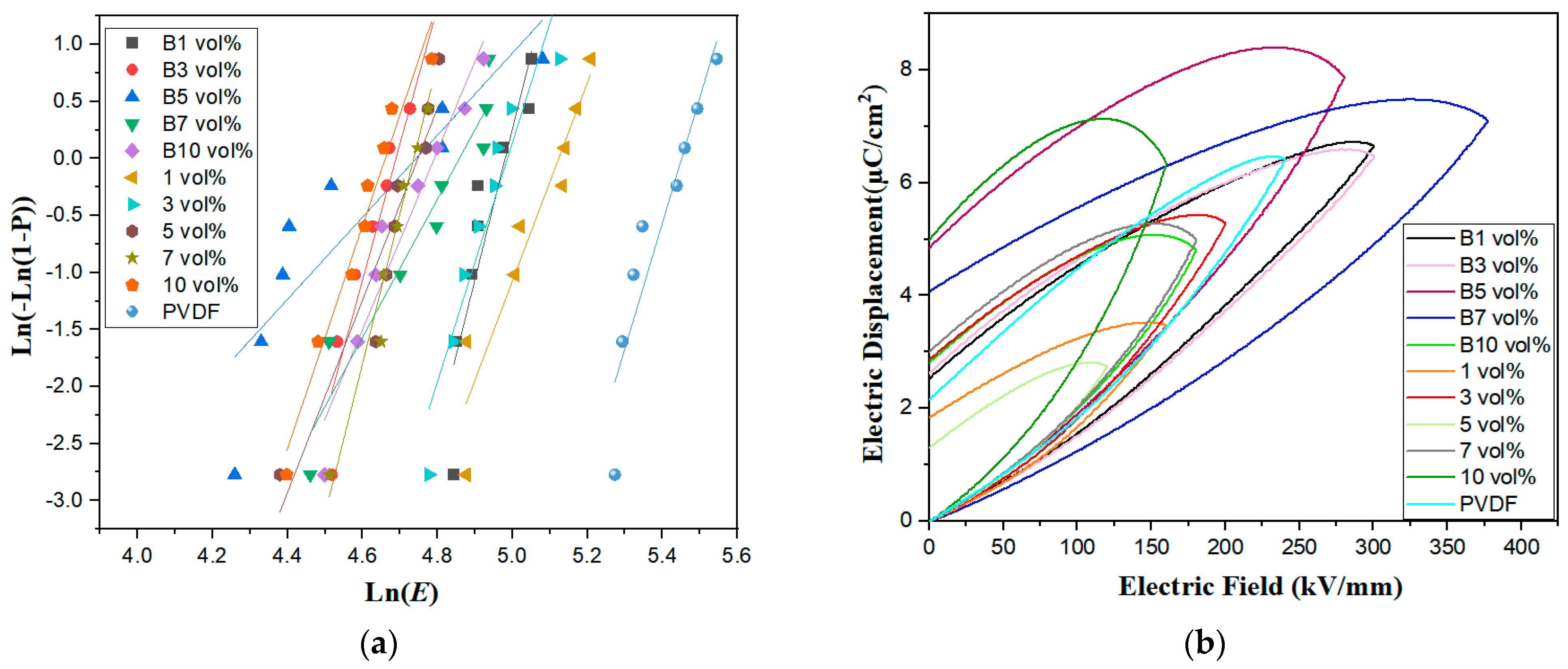
| Sample | Eb (kV/mm) | β |
|---|---|---|
| 0 vol% | 226 | 12.49 |
| 1 vol%/B1 vol% | 166/144 | 10.26/13.47 |
| 3 vol%/B3 vol% | 145/108 | 9.58/11.87 |
| 5 vol%/B5 vol% | 113/112 | 12.27/3.57 |
| 7 vol%/B7 vol% | 113/126 | 16.54/7.67 |
| 10 vol%/B10 vol% | 104/119 | 9.90/8.04 |
| Sample | Electric Fields (kV/mm) | Potential Shifts (µC/cm2) | Residual Polarization (µC/cm2) |
|---|---|---|---|
| 0 vol% | 260 | 6.38 | 2.15 |
| 1 vol%/B1 vol% | 160/300 | 3.46/6.65 | 1.83/2.52 |
| 3 vol%/B3 vol% | 200/300 | 5.30/6.47 | 2.86/2.62 |
| 5 vol%/B5 vol% | 120/280 | 2.75/7.9 | 1.30/4.85 |
| 7 vol%/B7 vol% | 180/180 | 5.04/7.11 | 3.01/4.07 |
| 10 vol%/B10 vol% | 160/160 | 6.32/4.7 | 4.99/2.80 |
Disclaimer/Publisher’s Note: The statements, opinions and data contained in all publications are solely those of the individual author(s) and contributor(s) and not of MDPI and/or the editor(s). MDPI and/or the editor(s) disclaim responsibility for any injury to people or property resulting from any ideas, methods, instructions or products referred to in the content. |
© 2023 by the authors. Licensee MDPI, Basel, Switzerland. This article is an open access article distributed under the terms and conditions of the Creative Commons Attribution (CC BY) license (https://creativecommons.org/licenses/by/4.0/).
Share and Cite
Qiao, J.; Liu, Z.; Mu, H.; Liu, C. Effect of High-Entropy Spinel Ferrite (Mn0.2Zr0.2Cu0.2Ca0.2Ni0.2)Fe2O4 Doping Concentration on the Ferroelectric Properties of PVDF-Based Polymers. Polymers 2023, 15, 2688. https://doi.org/10.3390/polym15122688
Qiao J, Liu Z, Mu H, Liu C. Effect of High-Entropy Spinel Ferrite (Mn0.2Zr0.2Cu0.2Ca0.2Ni0.2)Fe2O4 Doping Concentration on the Ferroelectric Properties of PVDF-Based Polymers. Polymers. 2023; 15(12):2688. https://doi.org/10.3390/polym15122688
Chicago/Turabian StyleQiao, Jiale, Zhaoting Liu, Haiwei Mu, and Chao Liu. 2023. "Effect of High-Entropy Spinel Ferrite (Mn0.2Zr0.2Cu0.2Ca0.2Ni0.2)Fe2O4 Doping Concentration on the Ferroelectric Properties of PVDF-Based Polymers" Polymers 15, no. 12: 2688. https://doi.org/10.3390/polym15122688