
Analysis of the Self-Healing Capability of Thermoplastic Elastomer Capsules in a Polymeric Beam Structure Based on Strain Energy Release Behaviour during Crack Growth

 ,
,
Abstract
:1. Introduction
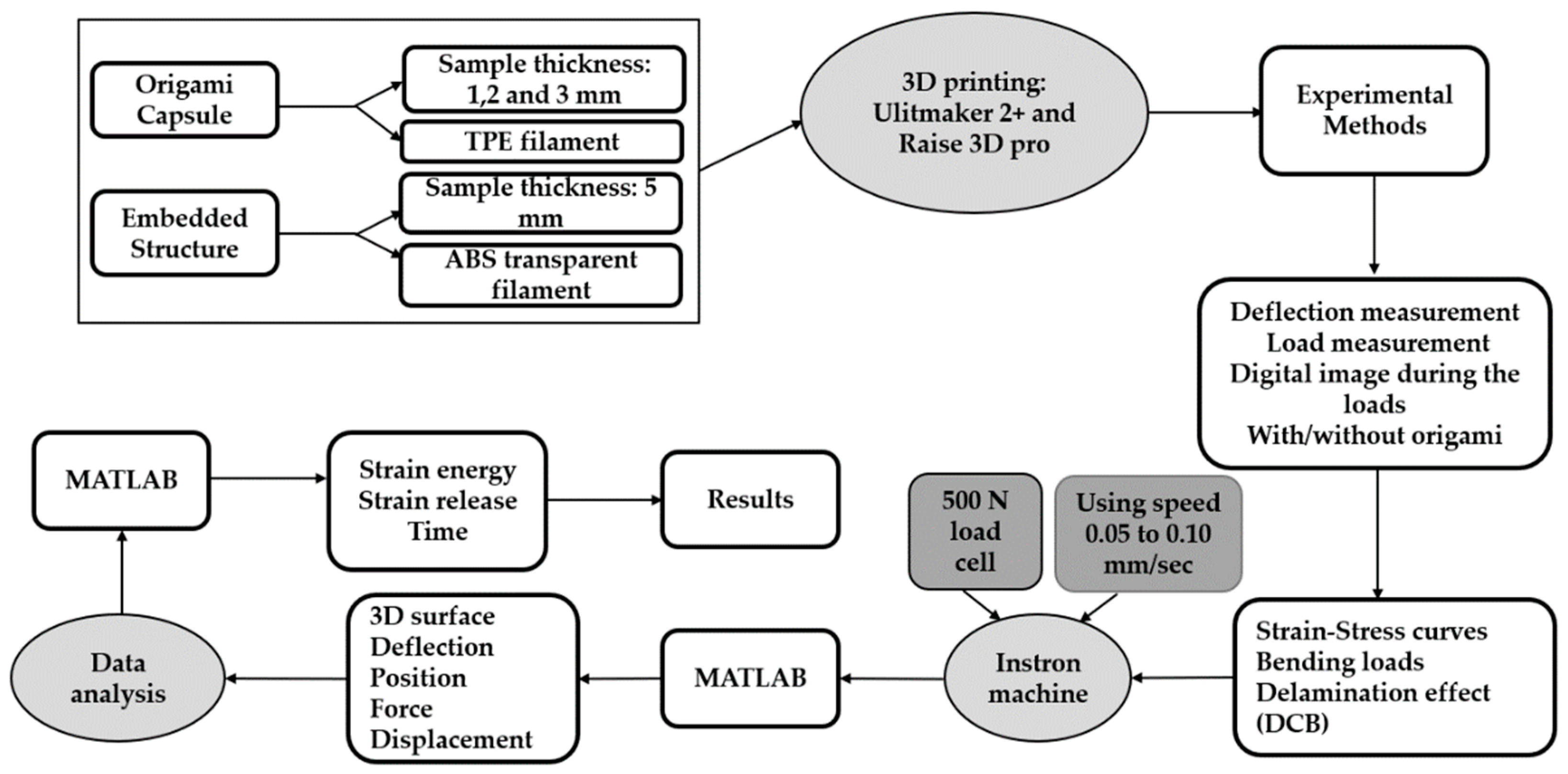
2. Methodology
2.1. Selection of Materials
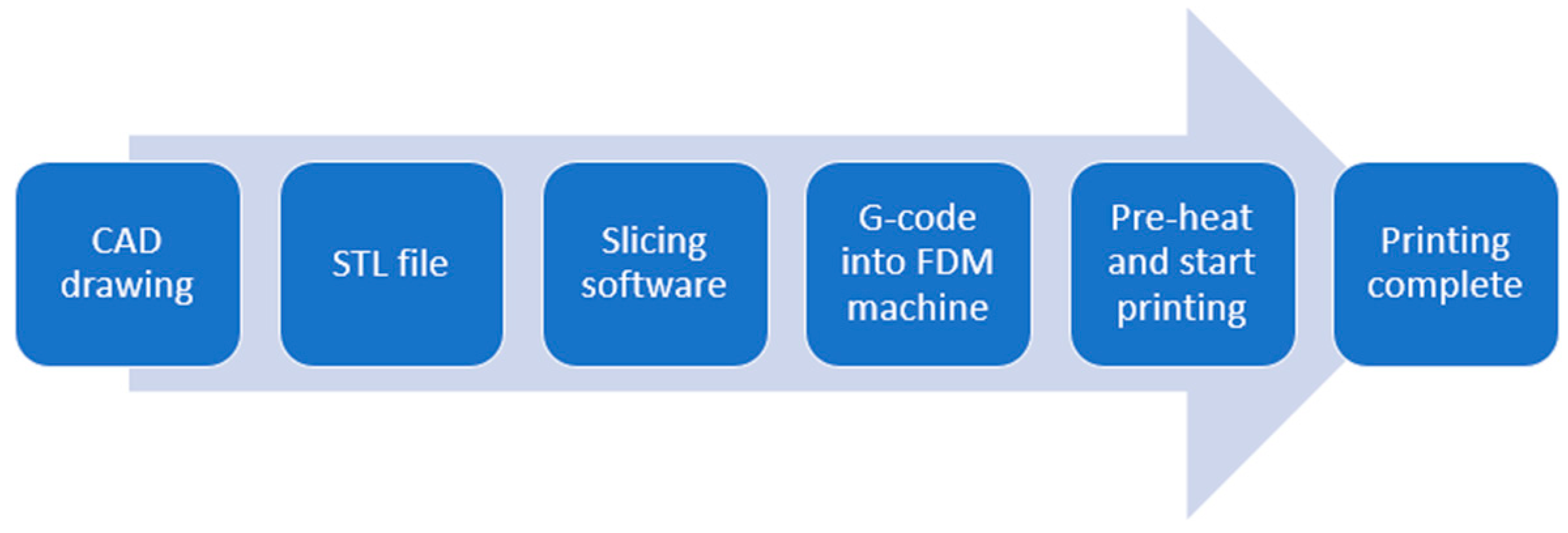
2.2. Specimen Preparation
2.3. Experimental Design
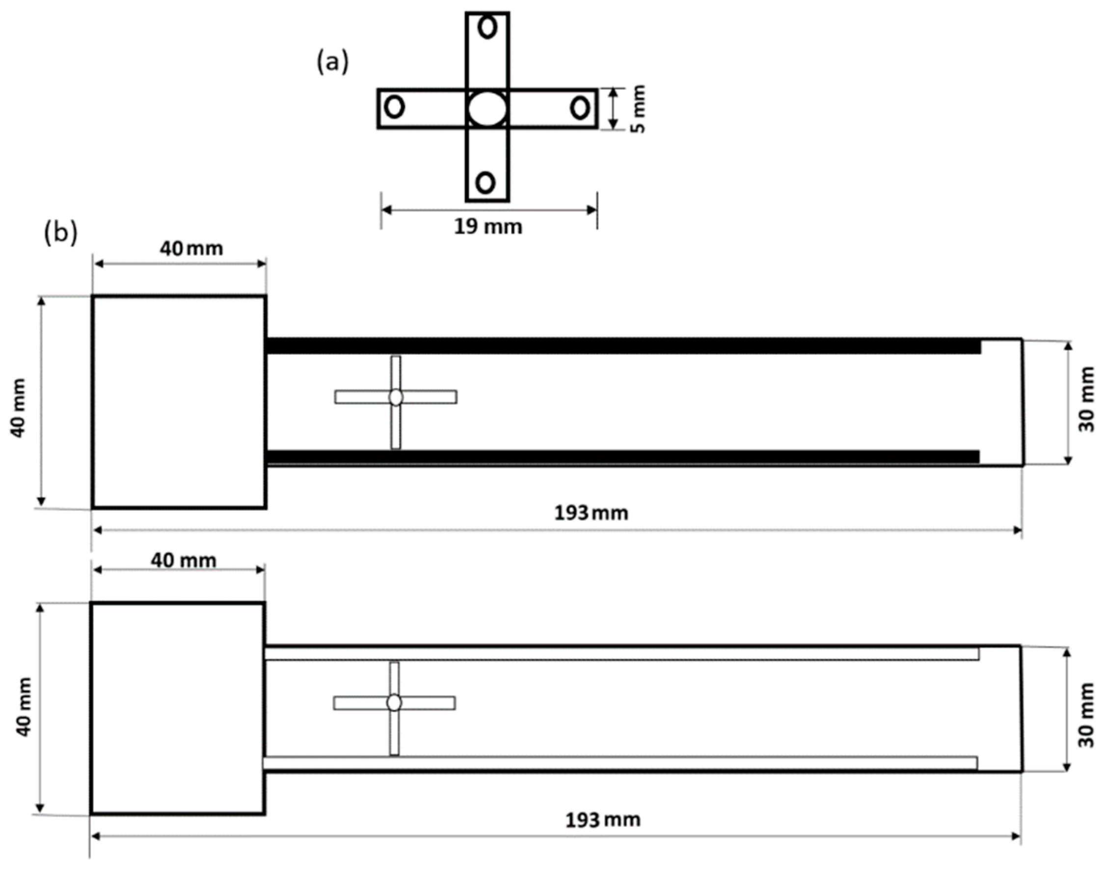
2.3.1. Origami Capsule
2.3.2. Origami Capsule Embedded Inside the Structure of the Beam
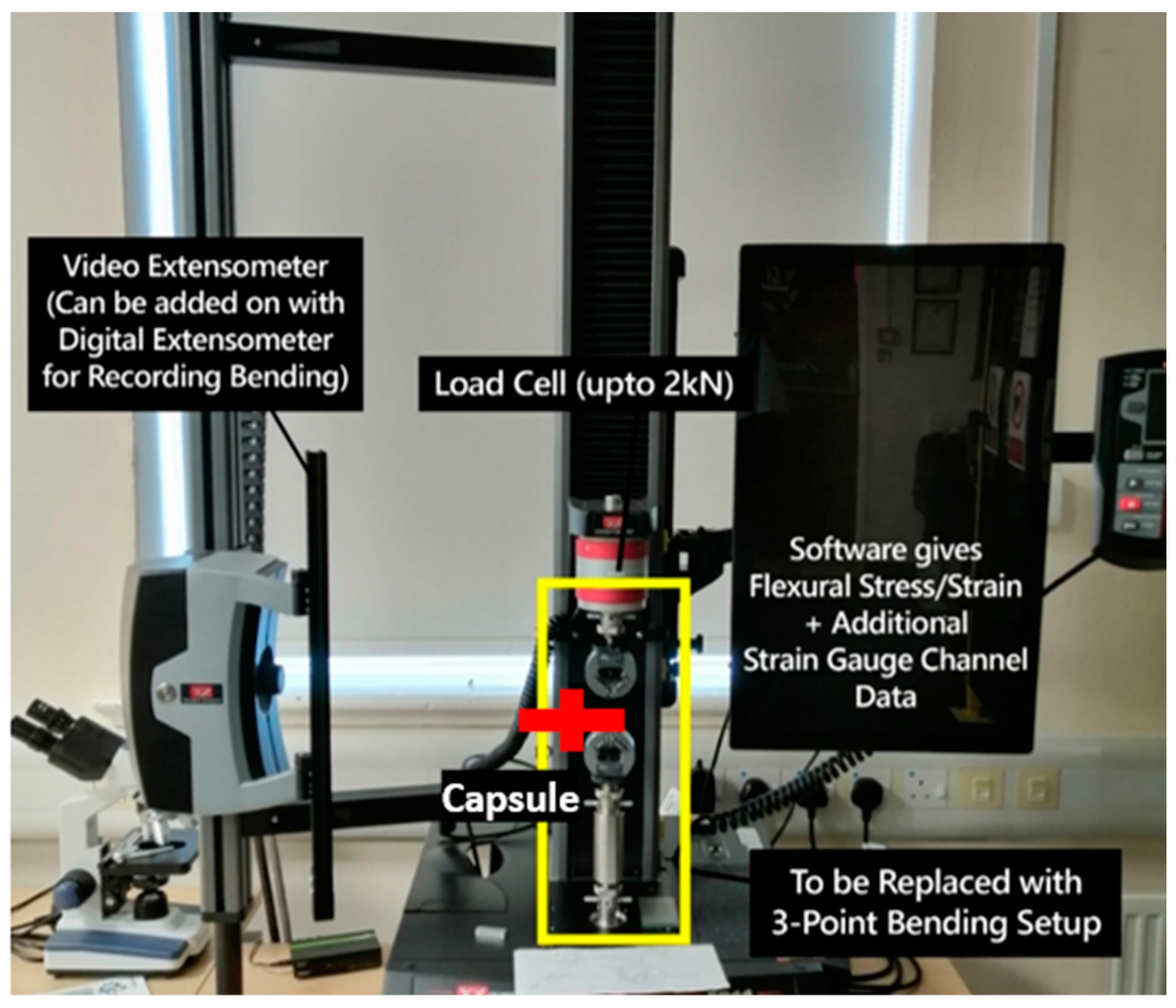
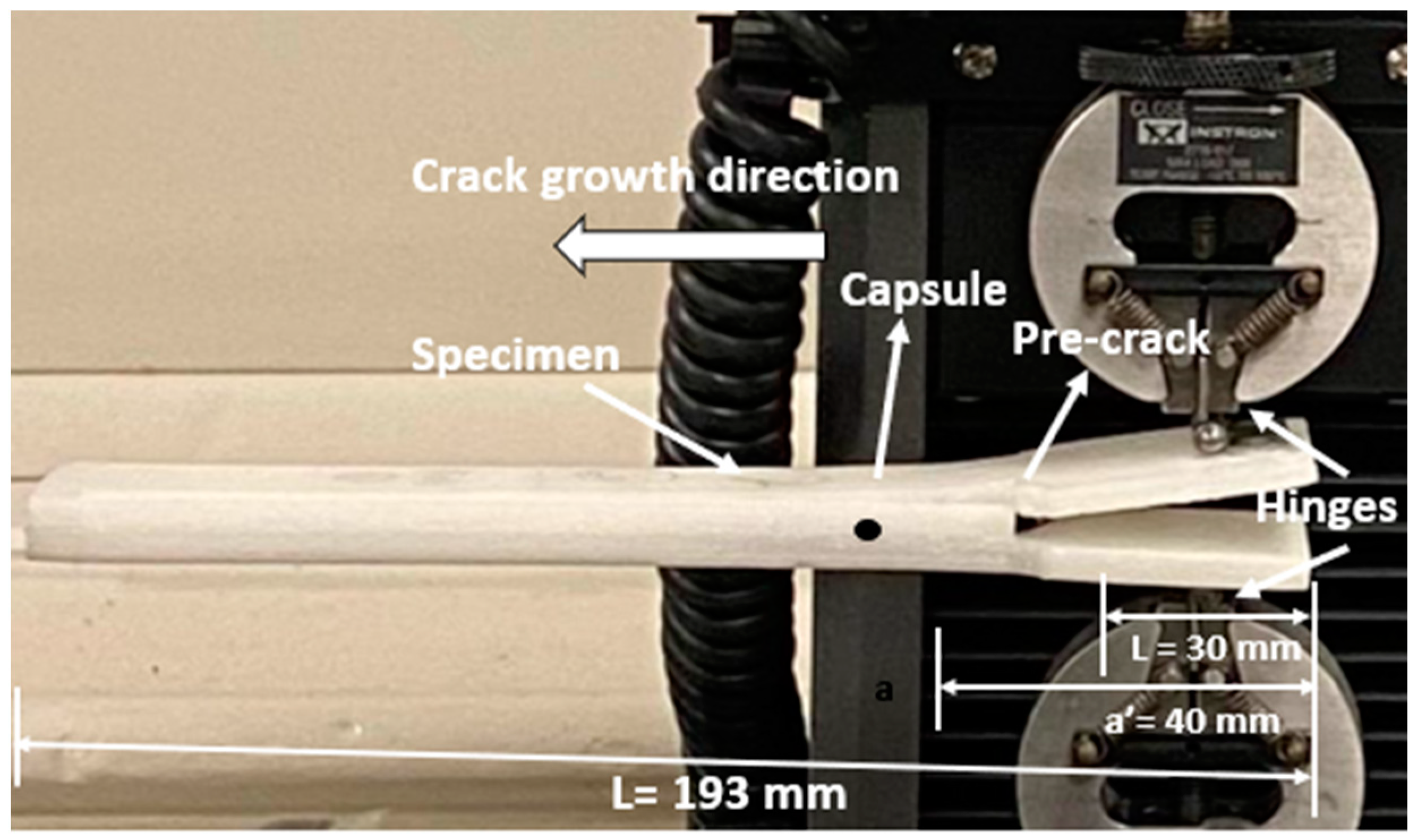
2.4. Experiment Procedure and Setup
2.4.1. Polymeric Origami Capsule Behaviour
2.4.2. Analysis of the Beam’s Behaviour when the Origami Capsule Is Present within it
3. Results and Discussion
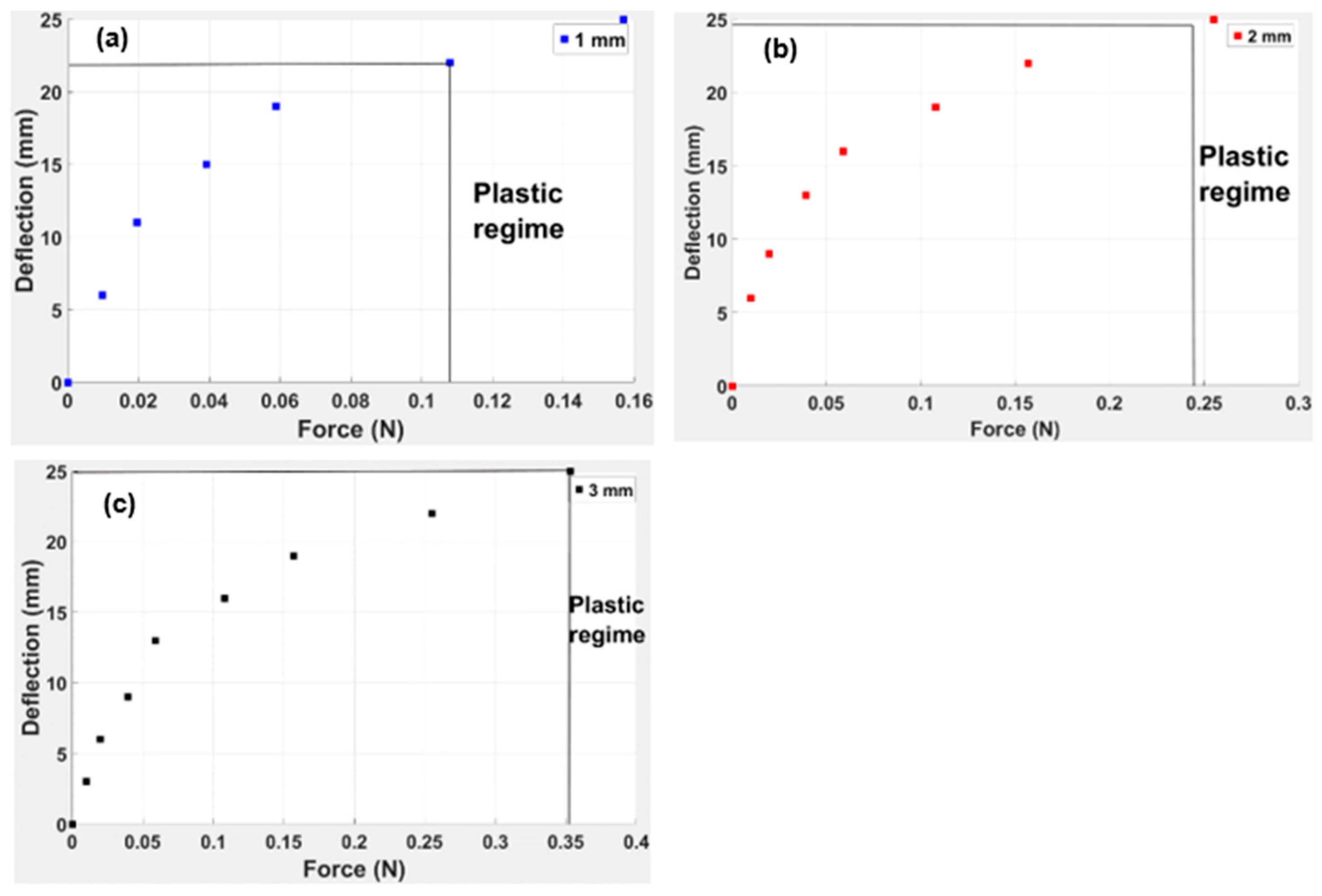
3.1. The Bending Moment of TPE “Cross” Origami Capsule Test Results
3.2. Discussion of the TPE “Cross” Origami Capsule Behaviour
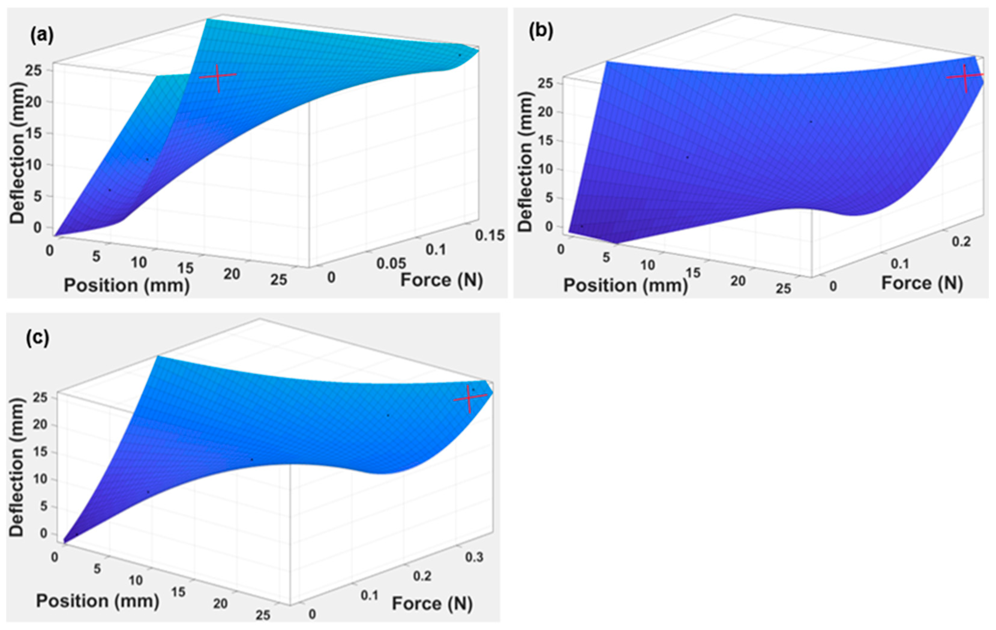
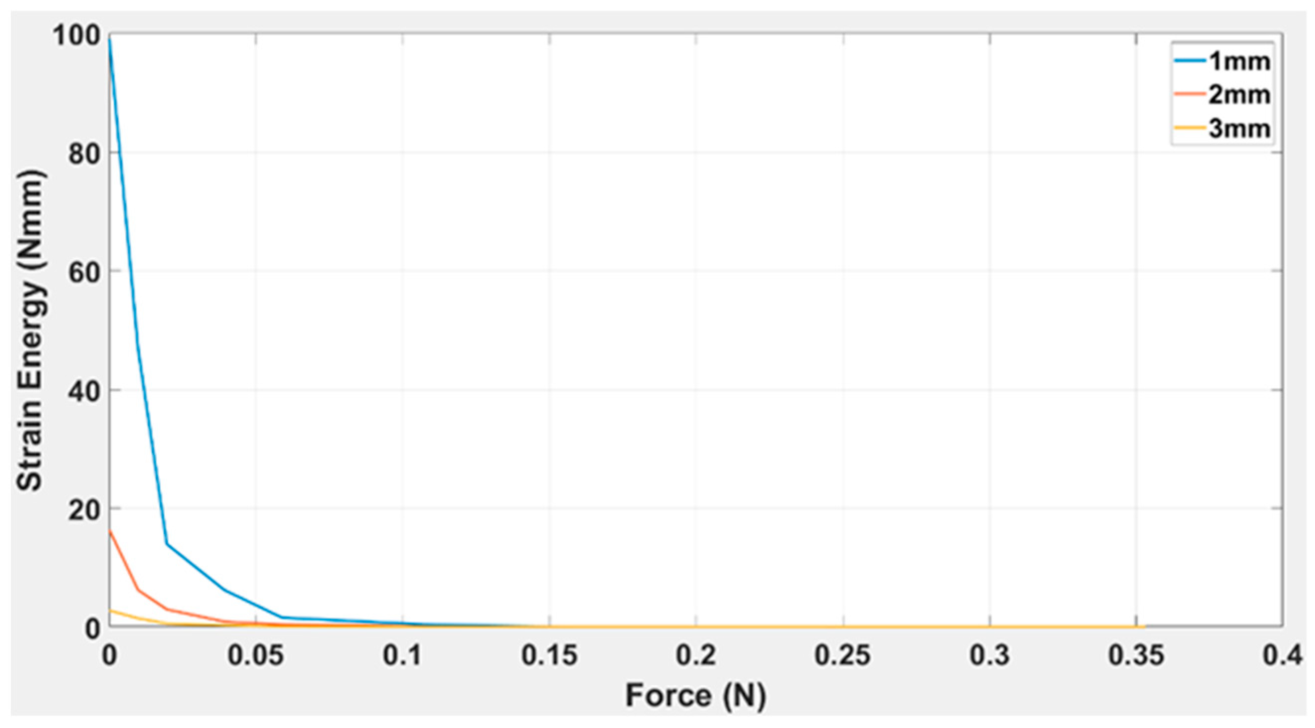
3.3. Embedded Structure of the TPE “Cross” Origami Capsule Inside DCB Results
Discussion
4. Conclusions
Author Contributions
Funding
Institutional Review Board Statement
Data Availability Statement
Conflicts of Interest
References
- Zhang, Z.; Demir, K.G.; Gu, G.X. Developments in 4D-Printing: A Review on Current Smart Materials, Technologies, and Applications. Int. J. Smart Nano Mater. 2019, 10, 205–224. [Google Scholar] [CrossRef] [Green Version]
- He, F.; Thakur, V.K.; Khan, M. Evolution and New Horizons in Modeling Crack Mechanics of 3D Printing Polymeric Structures. Mater. Today Chem. 2021, 20, 100393. [Google Scholar] [CrossRef]
- He, F.; Khan, M. Effects of Printing Parameters on the Fatigue Behaviour of 3d-Printed Abs under Dynamic Thermo-Mechanical Loads. Polymers 2021, 13, 2362. [Google Scholar] [CrossRef] [PubMed]
- Chu, H.; Yang, W.; Sun, L.; Cai, S.; Yang, R.; Liang, W.; Yu, H.; Liu, L. 4D Printing: A Review on Recent Progresses. Micromachines 2020, 11, 796. [Google Scholar] [CrossRef] [PubMed]
- Yang, P.; Zhu, F.; Zhang, Z.; Cheng, Y.; Wang, Z.; Li, Y. Stimuli-Responsive Polydopamine-Based Smart Materials. Chem. Soc. Rev. 2021, 50, 8319–8343. [Google Scholar] [CrossRef] [PubMed]
- Khan, N.I.; Halder, S.; Gunjan, S.B.; Prasad, T. A Review on Diels-Alder Based Self-Healing Polymer Composites. IOP Conf. Ser. Mater. Sci. Eng. 2018, 377, 012007. [Google Scholar] [CrossRef]
- Willocq, B.; Odent, J.; Dubois, P.; Raquez, J.M. Advances in Intrinsic Self-Healing Polyurethanes and Related Composites. RSC Adv. 2020, 10, 13766–13782. [Google Scholar] [CrossRef]
- Li, X.; Yu, R.; He, Y.; Zhang, Y.; Yang, X.; Zhao, X.; Huang, W. Self-Healing Polyurethane Elastomers Based on a Disulfide Bond by Digital Light Processing 3D Printing. ACS Macro Lett. 2019, 8, 1511–1516. [Google Scholar] [CrossRef]
- Zentner, C.A.; Anson, F.; Thayumanavan, S.; Swager, T.M. Dynamic Imine Chemistry at Complex Double Emulsion Interfaces. J. Am. Chem. Soc. 2019, 141, 18048–18055. [Google Scholar] [CrossRef]
- Zhang, Z.P.; Rong, M.Z.; Zhang, M.Q. Mechanically Robust, Self-Healable, and Highly Stretchable “Living” Crosslinked Polyurethane Based on a Reversible C–C Bond. Adv. Funct. Mater. 2018, 28, 1706050. [Google Scholar] [CrossRef]
- Almutairi, M.D.; Aria, A.I.; Thakur, V.K.; Khan, M.A. Self-Healing Mechanisms for 3D-Printed Polymeric Structures: From Lab to Reality. Polymers 2020, 12, 1534. [Google Scholar] [CrossRef] [PubMed]
- Anand, L.D.V.; Hepsiba, D.; Palaniappan, S.; Sumathy, B.; Vijayakumar, P.; Rani, S.S. Automatic Strain Sensing Measurement on Steel Beam Using Strain Gauge. Mater. Today Proc. 2021, 45, 2578–2580. [Google Scholar] [CrossRef]
- Alshammari, Y.L.A.; He, F.; Khan, M.A. Modelling and Investigation of Crack Growth for 3d-Printed Acrylonitrile Butadiene Styrene (Abs) with Various Printing Parameters and Ambient Temperatures. Polymers 2021, 13, 3737. [Google Scholar] [CrossRef]
- Meulman, E.; Renart, J.; Carreras, L.; Zurbitu, J. A Methodology for the Experimental Characterization of Energy Release Rate-Controlled Creep Crack Growth under Mode I Loading. Eng. Fract. Mech. 2023, 283, 109222. [Google Scholar] [CrossRef]
- Santos, P.; Silva, P. Effect of Carbon Nanofibers on the Strain Rate and Interlaminar Shear Strength of Carbon/Epoxy Composites. Materials 2023, 16, 4332. [Google Scholar] [CrossRef] [PubMed]
- Wen, N.; Song, T.; Ji, Z.; Jiang, D.; Wu, Z.; Wang, Y.; Guo, Z. Recent Advancements in Self-Healing Materials: Mechanicals, Performances and Features. React. Funct. Polym. 2021, 168, 105041. [Google Scholar] [CrossRef]
- Speck, O.; Speck, T. An Overview of Bioinspired and Biomimetic Self-Repairing Materials. Biomimetics 2019, 4, 26. [Google Scholar] [CrossRef] [Green Version]
- Xiong, C.; Wang, T.; Zhao, Z.; Ni, Y. Recent Progress in the Development of Smart Supercapacitors. SmartMat 2023, 4, e1158. [Google Scholar] [CrossRef]
- Irzhak, V.I.; Uflyand, I.E.; Dzhardimalieva, G.I. Self-Healing of Polymers and Polymer Composites. Polymers 2022, 14, 5404. [Google Scholar] [CrossRef] [PubMed]
- Grammatikopoulos, A.; Banks, J.; Temarel, P. Experimental Dynamic Properties of ABS Cellular Beams Produced Using Additive Manufacturing. In Proceedings of the 18th European Conference on Composite Materials, Athens, Greece, 24–28 June 2018. [Google Scholar]
- Mondal, S.; Ghuku, S.; Saha, K.N. Effect of Clamping Torque on Large Deflection Static and Dynamic Response of a Cantilever Beam: An Experimental Study. Int. J. Eng. Technol. 2018, 15, 1–16. [Google Scholar] [CrossRef]
- Brown, E.N.; Sottos, N.R.; White, S.R. Fracture Testing of a Self-Healing Polymer Composite. Exp. Mech. 2002, 42, 372–379. [Google Scholar] [CrossRef]
- Siddique, A.; Abid, S.; Shafiq, F.; Nawab, Y.; Wang, H.; Shi, B.; Saleemi, S.; Sun, B. Mode I Fracture Toughness of Fiber-Reinforced Polymer Composites: A Review. J. Ind. Text. 2021, 50, 1165–1192. [Google Scholar] [CrossRef]
- Pati, S.; Singh, B.P.; Dhakate, S.R. Self-Healing Polymer Composites Based on Graphene and Carbon Nanotubes; AG 2017; Ponnamma, D., Sadasivuni, K.K., Cabibihan, J.J., Al-Maadeed, M.A.-A., Eds.; Springer: New Delhi, India, 2017; ISBN 978-3-319-50423-0. [Google Scholar]
- Hu, Z.; Zhang, D.; Lu, F.; Yuan, W.; Xu, X.; Zhang, Q.; Liu, H.; Shao, Q.; Guo, Z.; Huang, Y. Multistimuli-Responsive Intrinsic Self-Healing Epoxy Resin Constructed by Host-Guest Interactions. Am. Chem. Soc. 2018, 51, 5294–5303. [Google Scholar] [CrossRef]
- Peraza Hernandez, E.A.; Hartl, D.J.; Lagoudas, D.C. Structural Mechanics and Design of Active Origami Structures. In Active Origami; Springer: Berlin/Heidelberg, Germany, 2019; pp. 331–409. [Google Scholar]
- He, F.; Ning, H.; Khan, M. Effect of 3D Printing Process Parameters on Damping Characteristic of Cantilever Beams Fabricated Using Material Extrusion. Polymers 2023, 15, 257. [Google Scholar] [CrossRef] [PubMed]
- Li, Y.; You, Z. Open-Section Origami Beams for Energy Absorption. Int. J. Mech. Sci. 2019, 157, 741–757. [Google Scholar] [CrossRef]
- Mashkoor, F.; Lee, S.J.; Yi, H.; Noh, S.M.; Jeong, C. Self-Healing Materials for Electronics Applications. Int. J. Mol. Sci. 2022, 23, 622. [Google Scholar] [CrossRef] [PubMed]
- Zhang, W.; Zheng, Q.; Ashour, A.; Han, B. Self-Healing Cement Concrete Composites for Resilient Infrastructures: A Review. Compos. B Eng. 2020, 189, 107892. [Google Scholar] [CrossRef]
- Nodehi, M.; Ozbakkaloglu, T.; Gholampour, A. A Systematic Review of Bacteria-Based Self-Healing Concrete: Biomineralization, Mechanical, and Durability Properties. J. Build. Eng. 2022, 49, 104038. [Google Scholar] [CrossRef]
- Maddalena, R.; Bonanno, L.; Balzano, B.; Tuinea-Bobe, C.; Sweeney, J.; Mihai, I. A Crack Closure System for Cementitious Composite Materials Using Knotted Shape Memory Polymer (k-SMP) Fibres. Cem. Concr. Compos. 2020, 114, 103757. [Google Scholar] [CrossRef]
- Zai, B.A.; Khan, M.A.; Khan, S.Z.; Asif, M.; Khan, K.A.; Saquib, A.N.; Mansoor, A.; Shahzad, M.; Mujtaba, A. Prediction of Crack Depth and Fatigue Life of an Acrylonitrile Butadiene Styrene Cantilever Beam Using Dynamic Response. J. Test Eval. 2020, 48, 20180674. [Google Scholar] [CrossRef]
- Jagadeesh, P.; Puttegowda, M.; Rangappa, S.M.; Alexey, K.; Gorbatyuk, S.; Khan, A.; Doddamani, M.; Siengchin, S. A Comprehensive Review on 3D Printing Advancements in Polymer Composites: Technologies, Materials, and Applications; Springer: London, UK, 2022; Volume 121, ISBN 0123456789. [Google Scholar]
- Dhaliwal, G.S.; Dundar, M.A. Four Point Flexural Response of Acrylonitrile–Butadiene–Styrene. J. Compos. Sci. 2020, 4, 63. [Google Scholar] [CrossRef]
- Lee, T.U.; You, Z.; Gattas, J.M. Elastica Surface Generation of Curved-Crease Origami. Int. J. Solids Struct. 2018, 136–137, 13–27. [Google Scholar] [CrossRef]
- Damas, S.M.; Turner, C.J. The Material Testing of Nanoparticle Doped 3D Printed ABS Strain Gages for Resistance and Stiffness. In Proceedings of the International Design Engineering Technical Conferences and Computers and Information in Engineering Conference IDETC/CIE2020, Virtual, Online, 17–19 August 2020; pp. 1–9. [Google Scholar]
- Ritzen, L.; Montano, V.; Garcia, S.J. 3d Printing of a Self-Healing Thermoplastic Polyurethane through Fdm: From Polymer Slab to Mechanical Assessment. Polymers 2021, 13, 305. [Google Scholar] [CrossRef] [PubMed]
- UL Prospector Generic Families of Plastic. Available online: https://www.ulprospector.com/plastics/en/generics (accessed on 15 September 2021).
- Srivastava, V.K. A Review on Advances in Rapid Prototype 3D Printing of Multi-Functional Applications. Sci. Technol. 2017, 7, 4–24. [Google Scholar]
- Almutairi, M.D.; Khan, M.A. Experimental Investigation of Polymeric Beam Under Elastic and Plastic Loads. Int. J. Appl. Phys. Sci. 2022, 8, 15–21. [Google Scholar] [CrossRef]
- Almutairi, M.D.; Alnahdi, S.S.; Khan, M.A. Strain Release Behaviour during Crack Growth of a Polymeric Beam under Elastic Loads for Self-Healing. Polymers 2022, 14, 3102. [Google Scholar] [CrossRef] [PubMed]
- Blaiszik, B.J.; Kramer, S.L.B.; Olugebefola, S.C.; Moore, J.S.; Sottos, N.R.; White, S.R. Self-Healing Polymers and Polymer Composites. Annu. Rev. Ofmater. Res. 2010, 40, 179–211. [Google Scholar] [CrossRef]
- Drake, D.A.; Sullivan, R.W.; Lovejoy, A.E.; Clay, S.B.; Jegley, D.C. Influence of Stitching on the Out-of-Plane Behavior of Composite Materials—A Mechanistic Review. J. Compos. Mater. 2021, 55, 3307–3321. [Google Scholar] [CrossRef]
- Kessler, M.R.; Sottos, N.R.; White, S.R. Self-Healing Structural Composite Materials. Compos. Part A Appl. Sci. Manuf. 2003, 34, 743–753. [Google Scholar] [CrossRef]


| Parameters | Value |
|---|---|
| Nozzle size (mm) | 0.4 |
| Layer thickness (mm) | 0.1, 0.2 |
| Build orientation | 0°, ±45° |
| Infill density (%) | 100 |
| Origami Capsule Shape (TPE) | Thickness (mm) | Dimensions (mm) | Loads (g) |
|---|---|---|---|
| Cross | 1.0, 2.0, 3.0 | 19 L/5 W | 1, 2, 4, 6, 11, 16, 26, 36, 56, 86, 106 |
| Type of Specimen | Crack Length | Capsules | Mechanical Testing |
|---|---|---|---|
| With origami | 40 mm | 1 mm, 2 mm, 3 mm | Delamination test |
| Without origami | - | - |
| Specimen | Structure Thickness (mm) | Dimensions (mm) (Length/Width) | Structure Species |
|---|---|---|---|
| With origami capsule | 5 mm | 193 L/30 W | |
| Without origami capsule | 5 mm | 193 L/30 W | With holes and pillars, see Figure 4b |
| T00 | T10 | T01 | T20 | T11 | R-Square | |
|---|---|---|---|---|---|---|
| 1 | 0.2492 | −137 | 2.373 | 2086 | −16.41 | 0.9991 |
| 2 | 0.7806 | 389.9 | 0.3744 | 513.1 | −18.49 | 0.994 |
| 3 | 0.6838 | 86.07 | 1.134 | 329.1 | −8.55 | 0.9965 |
| The experimental value of strain energy release | ||
| Theoretical model value of strain energy release | ||
| Percent deviation in strain energy release | = 0.183 (18.31) | = 0.233 (23.3) |
Disclaimer/Publisher’s Note: The statements, opinions and data contained in all publications are solely those of the individual author(s) and contributor(s) and not of MDPI and/or the editor(s). MDPI and/or the editor(s) disclaim responsibility for any injury to people or property resulting from any ideas, methods, instructions or products referred to in the content. |
© 2023 by the authors. Licensee MDPI, Basel, Switzerland. This article is an open access article distributed under the terms and conditions of the Creative Commons Attribution (CC BY) license (https://creativecommons.org/licenses/by/4.0/).
Share and Cite
Almutairi, M.D.; He, F.; Alshammari, Y.L.; Alnahdi, S.S.; Khan, M.A. Analysis of the Self-Healing Capability of Thermoplastic Elastomer Capsules in a Polymeric Beam Structure Based on Strain Energy Release Behaviour during Crack Growth. Polymers 2023, 15, 3384. https://doi.org/10.3390/polym15163384
Almutairi MD, He F, Alshammari YL, Alnahdi SS, Khan MA. Analysis of the Self-Healing Capability of Thermoplastic Elastomer Capsules in a Polymeric Beam Structure Based on Strain Energy Release Behaviour during Crack Growth. Polymers. 2023; 15(16):3384. https://doi.org/10.3390/polym15163384
Chicago/Turabian StyleAlmutairi, Mohammed Dukhi, Feiyang He, Yousef Lafi Alshammari, Sultan Saleh Alnahdi, and Muhammad Ali Khan. 2023. "Analysis of the Self-Healing Capability of Thermoplastic Elastomer Capsules in a Polymeric Beam Structure Based on Strain Energy Release Behaviour during Crack Growth" Polymers 15, no. 16: 3384. https://doi.org/10.3390/polym15163384