
Cryogenic Mechanical Properties and Stability of Polymer Films for Liquid Oxygen Hoses
Abstract
:1. Introduction
2. Experimental Section
2.1. Materials
2.2. Sample Preparation and Treatment
2.3. Characterization
2.3.1. Liquid Oxygen Compatibility Test
2.3.2. Cryogenic Tensile Test
2.3.3. Structural and Surface Characterizations
3. Results and Discussions
3.1. The Liquid Oxygen Compatibility of These Polymers
3.2. Mechanical Properties
3.2.1. The Effect of LOX Immersion on the Cryogenic Mechanical Properties
3.2.2. The Mechanical Properties after Immersion in LN2
3.3. SEM Analysis
3.4. Chemical Structure Analysis
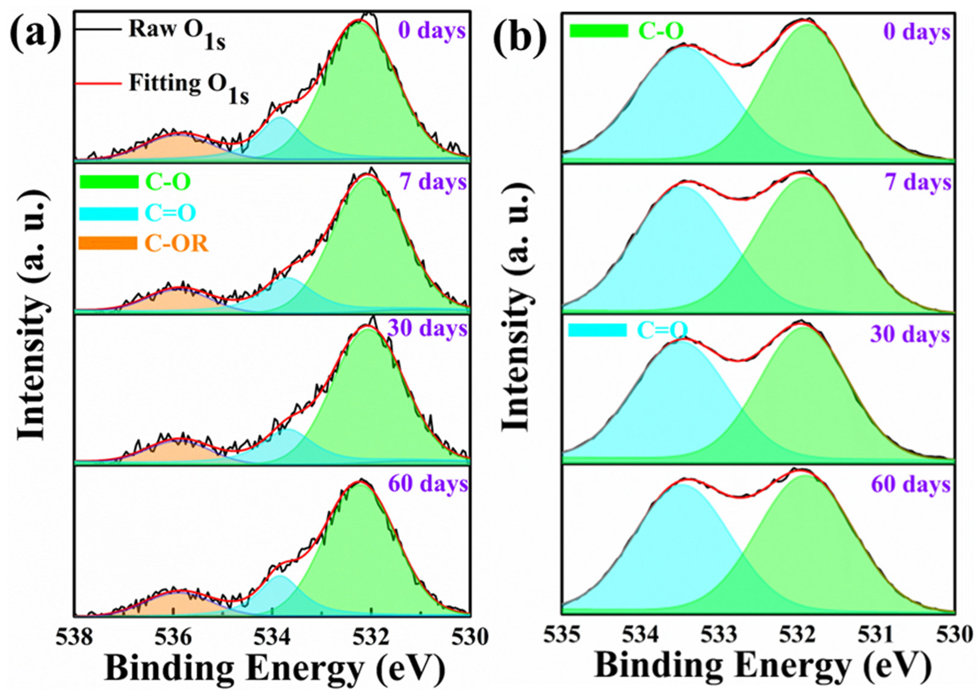
3.4.1. XPS Analysis
3.4.2. EDS Analysis
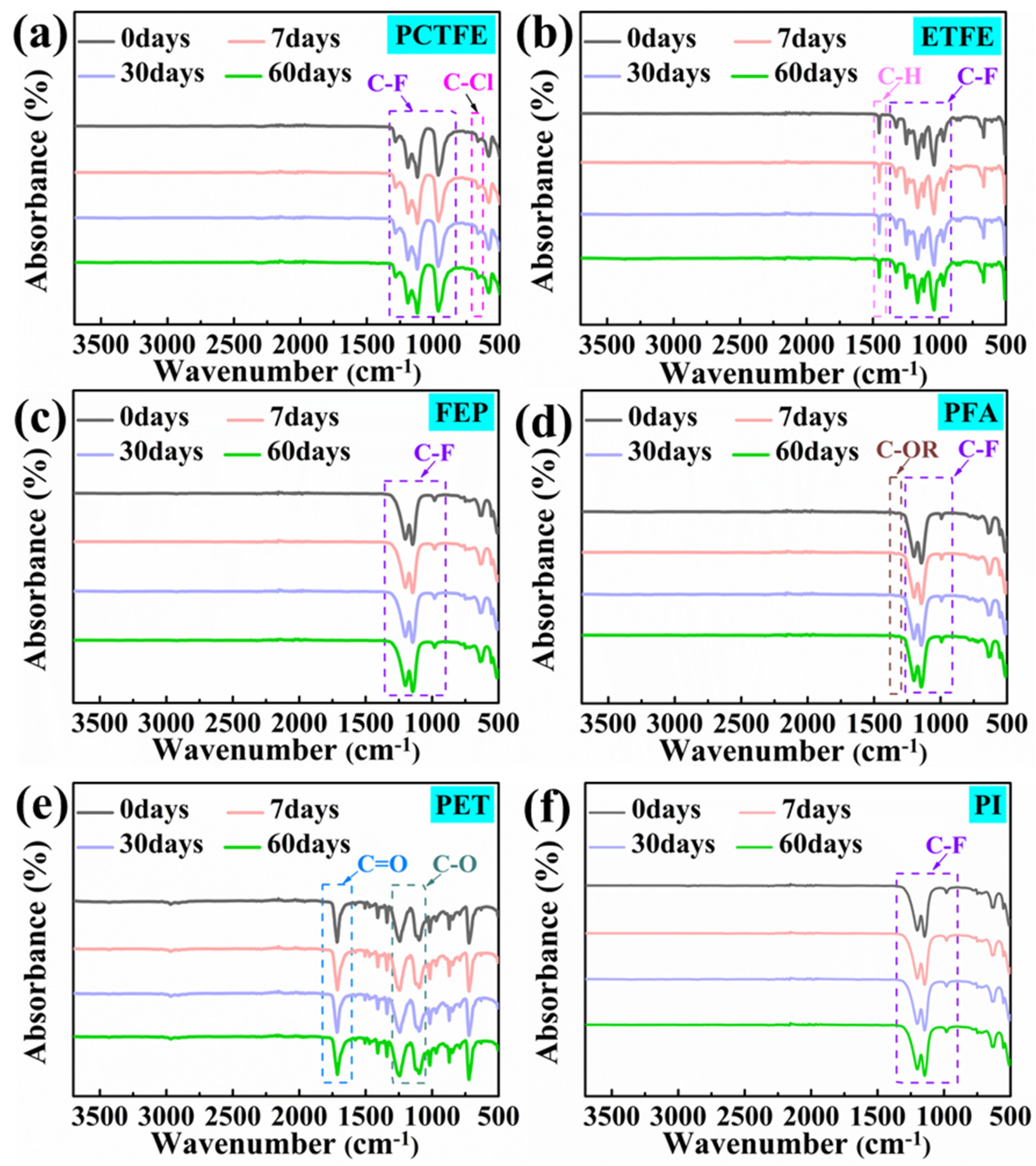
3.4.3. ATR Analysis
3.5. Crystal Phase Structure Analysis
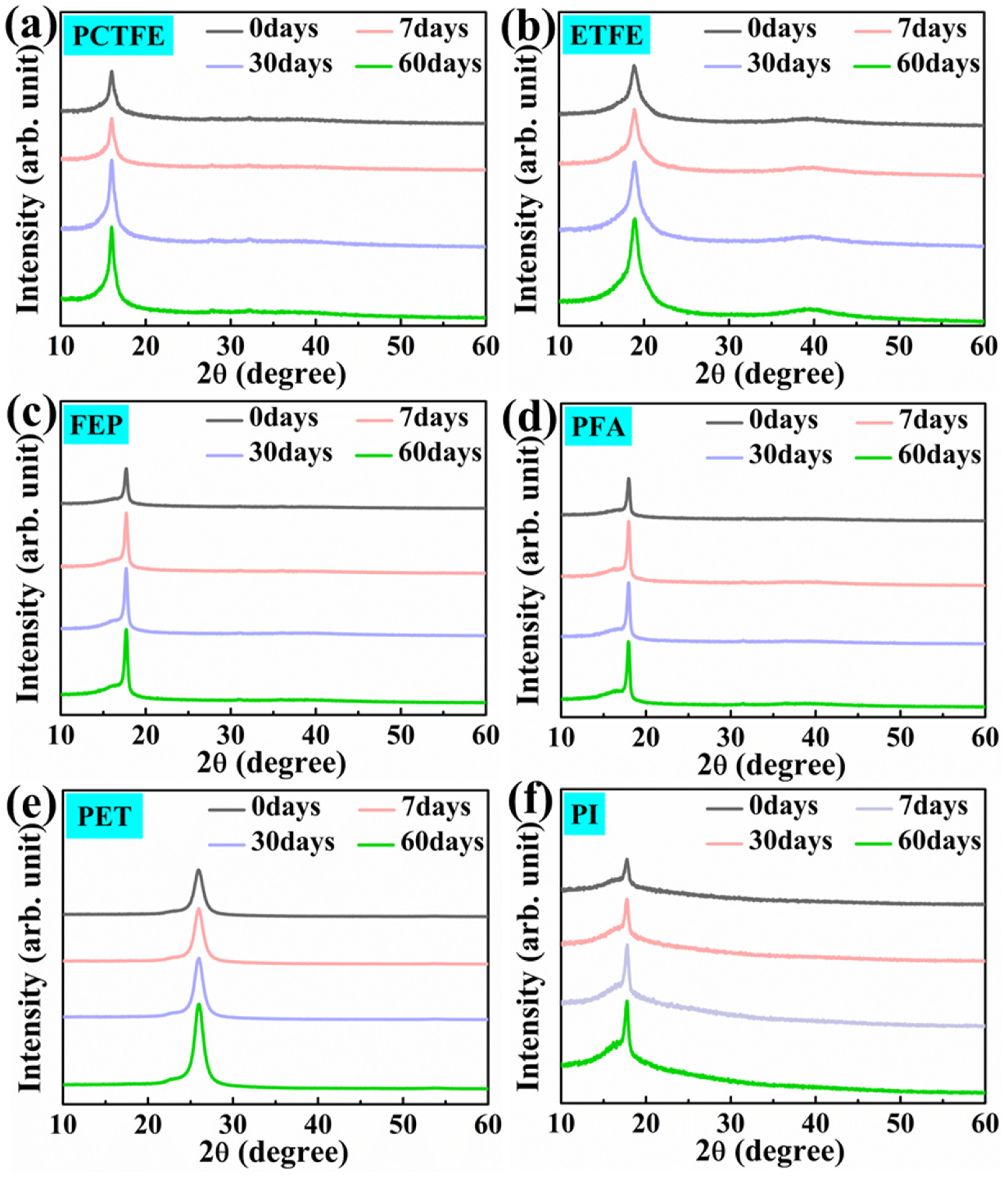
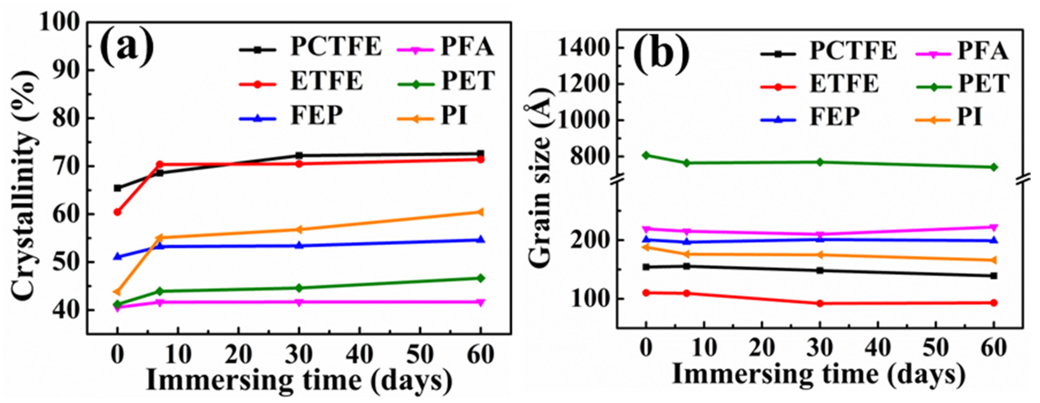
3.5.1. XRD Analysis after Immersion in Liquid Oxygen
3.5.2. XRD Analysis after Immersion in LN2
4. Conclusions
- (1)
- The four fluoropolymers were compatible with LOX and remained unchanged after immersion in LOX for 60 days. PET and PI exhibited incompatibility with LOX and could not be used in liquid oxygen directly. But their LOC could be improved by coating fluorine on the surface.
- (2)
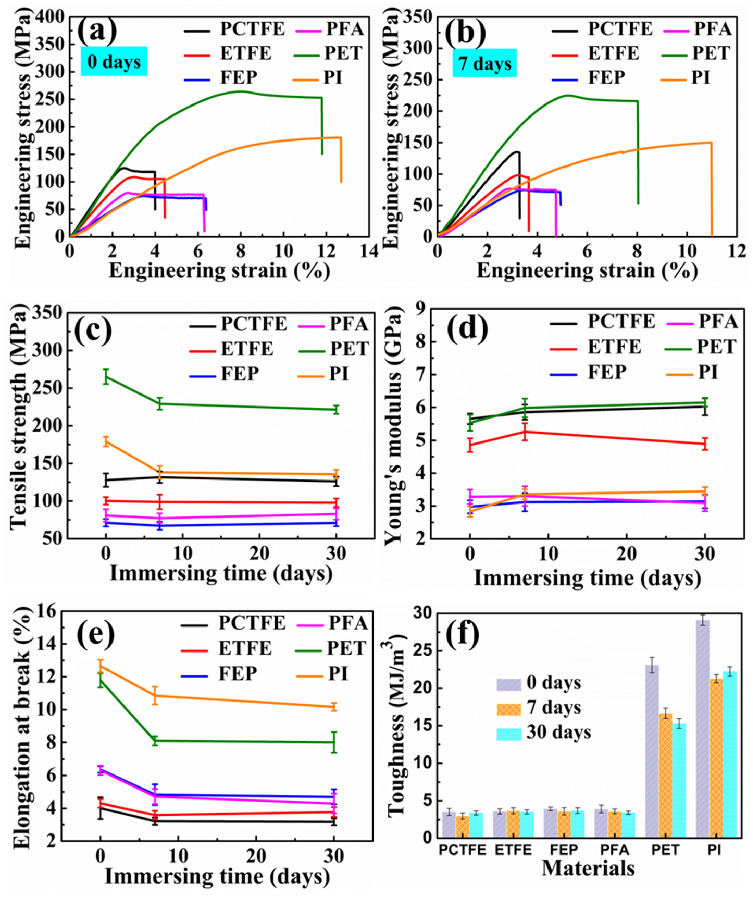
- Four fluoropolymer films and two non-fluoropolymer film materials still exhibited a certain strength and toughness at 77 K. Moreover, the cryogenic mechanical properties of PET and PI had always been superior to the four fluoropolymer film materials before and after immersion in LOX.
- (3)
- With the increase in immersion time in LOX, the cryogenic mechanical properties of PET and PI were more easily affected, while the four fluoropolymers were relatively stable. In addition, the changes in cryogenic mechanical properties of these polymer films were caused by the changes in crystallinity and grain size because of the ultra-low temperature of LOX and were not related to the strong oxidation of LOX.
- (4)
- Four fluoropolymers can be used as the inner layer materials of liquid oxygen composite hoses. PCTFE is the preferred material, followed by ETFE. In addition, due to the excellent cryogenic mechanical properties, PET and PI can be used as intermediate or outer layers after fluorine coating treatment. This work provides suggestions for the material selection process in the design and development of liquid oxygen composite hoses.
Author Contributions
Funding
Institutional Review Board Statement
Data Availability Statement
Conflicts of Interest
References
- Bardi, F.C.; Tang, H.; Kulkarni, M.; Yin, X. Structural analysis of cryogenic flexible hose. In Proceedings of the ASME 2011 30th International Conference on Ocean, Offshore and Arctic Engineering, Rotterdam, The Netherlands, 19–24 June 2011; pp. 593–606. [Google Scholar] [CrossRef]
- Buitrago, J.; Slocum, S.T.; Hudak, S.J.; Long, R. Cryogenic structural performance of corrugated pipe. In Proceedings of the ASME 2010 29th International Conference on Ocean, Offshore and Arctic Engineering, Shanghai, China, 7–11 June 2010; pp. 331–342. [Google Scholar] [CrossRef]
- Ston, J.B.; Ehrhardt, M.E.; Johnston, A.B.; Nusser, S. Offshore LNG Loading Problem Solved. Gas Tech. 2000. Available online: https://www.impac.de/fileadmin/content/Downloads/15_Offshore_LNG_gastech_2003.pdf (accessed on 26 June 2023).
- Mallon, N.; Weijde, G.V.D. Influence of hysteresis on the dynamics of cryogenic LNG composite hoses. In Proceedings of the ASME 2011 30th International Conference on Ocean, Offshore and arctic Engineering, Rotterdam, The Netherlands, 19–24 June 2011; pp. 199–208. [Google Scholar] [CrossRef]
- Bokhorst, E.V.; Twerda, A. Integrity and efficiency in LNG transfer operations with flexibles. In Proceedings of the International Petroleum Technology Conference, Doha, Qatar, 19–22 January 2014; p. IPTC-17662-MS. [Google Scholar] [CrossRef]
- Szekely, G.; Peixoto, E. Flexible hose technology benefits for ship-to-shore high pressure natural gas transfer. In Proceedings of the Offshore Technology Conference, Houston, TX, USA, 30 April–3 May 2018; p. OTC-28893-MS. [Google Scholar] [CrossRef]
- Smith, E.M. Liquid oxygen for aerospace applications. Int. J. Hydrogen Energy 1989, 14, 831–837. [Google Scholar] [CrossRef]
- Klem, M.D.; Smith, T.D.; Wadel, M.F.; Meyer, M.L.; Free, J.M.; Cikanek, H.A. Liquid oxygen or liquid methane propulsion and cryogenic advanced development. In Proceedings of the 62th International Aeronautical Congress, Cape Town, South Africa, 3–7 October 2011; p. 20110016509. Available online: http://ntrs.nasa.gov/api/citations/20110016509/downloads/20110016509.pdf (accessed on 26 June 2023).
- Liu, N.; Ma, B.; Liu, F.; Huang, W.; Xu, B.; Qu, L.; Yang, Y. Progress in research on composite cryogenic propellant tank for large aerospace vehicles. Compos. Part A Appl. Sci. Manuf. 2021, 143, 106297. [Google Scholar] [CrossRef]
- Sui, Y.; Li, J.; Qiu, Z.; Cui, Y.; Cong, C.; Meng, X.; Ye, H.; Zhou, Q. Effects of the sintering temperature on the superior cryogenic toughness of ultra-high molecular weight polyethylene (UHMWPE). Chem. Eng. J 2022, 444, 136366. [Google Scholar] [CrossRef]
- Key, C.F.; Riehl, W.A. Compatibility of Materials with Liquid Oxygen, NASA TM X-985, Washington, USA. 1964. Available online: https://ntrs.nasa.gov/api/citations/19750065862/downloads/19750065862.pdf (accessed on 27 June 2023).
- Wang, H.; Li, S.; Yuan, Y.; Liu, X.; Sun, T.; Wu, Z. Study of the epoxy/amine equivalent ratio on thermal properties, cryogenic mechanical properties, and liquid oxygen compatibility of the bisphenol a epoxy resin containing phosphorus. High Perform. Polym. 2019, 32, 429–443. [Google Scholar] [CrossRef]
- Liu, N.; Wang, H.; Wang, S.; Xu, B.; Qu, L. Liquid oxygen compatibility and ultra-low-temperature mechanical properties of modified epoxy resin containing phosphorus and nitrogen. Polymers 2022, 14, 4343. [Google Scholar] [CrossRef]
- Clark, A.F.; Hust, J.G. A review of the compatibility of structural materials with oxygen. AIAA J. 1974, 12, 441–454. [Google Scholar] [CrossRef]
- DeLong, D.; Greason, J. Thermoplastic fluoropolymer composite material for lightweight, long-life, nonflammable tanks and structures. In Proceedings of the 48th AIAA/ASME/ASCE/AHS/ASC Structures, Structural Dynamics, and Materials Conference, Honolulu, HI, USA, 23–26 April 2007; Available online: https://arc.aiaa.org/doi/pdf/10.2514/6.2007-2025 (accessed on 27 June 2023).
- Teng, H. Overview of the development of the fluoropolymer industry. Appl. Sci. 2012, 2, 496–512. [Google Scholar] [CrossRef]
- Zou, J.; Zhang, M.; Huang, M.; Zhao, D.; Dai, Y. Structure, properties, and modification of polytrifluorochloroethylene: A Review. Front. Mater. 2022, 9, 824155. [Google Scholar] [CrossRef]
- Snyder, C.E.; Gschwender, L.J. Fluoropolymers in fluid and lubricant applications. Ind. Eng. Chem. Prod. Res. 1983, 22, 383–386. [Google Scholar] [CrossRef]
- Bonning, B. Mechanical Analysis and Predictions of Properties for Polymer Materials at Cryogenic Temperatures. Ph.D. Thesis, Tennessee Technological University, Cookeville, TN, USA, 2020. [Google Scholar]
- Ross, M. Cryogenic Mechanical Properties of Polychlorotrifluoroethylene. Master’s Thesis, Rice University, Houston, TX, USA, 1974. Available online: https://hdl.handle.net/1911/104804 (accessed on 1 July 2023).
- Giannetti, E. Semi-crystalline fluorinated polymers. Polym. Int. 2001, 50, 10–26. [Google Scholar] [CrossRef]
- Balachandran, U.B.; Gubser, D.U.; Hartwig, K.T.; Barddos, V.A. Advances in Cryogenic Engineering Materials, 2nd ed.; Curran Associates, Inc.: New York, NY, USA, 2013. [Google Scholar]
- Kalia, S. Cryogenic Processing: A Study of materials at low temperatures. J. Low Temp. Phys. 2010, 158, 934–945. [Google Scholar] [CrossRef]
- Indumathi, J.; Bijwe, J.; Ghosh, A.K.; Fahim, M.; Krishnaraj, N. Wear of cryo-treated engineering polymers and composites. Wear 1999, 225–229, 343–353. [Google Scholar] [CrossRef]
- Wu, T.; Liu, Y.; Li, N.; Huang, G.; Qu, C.; Xiao, H. Cryogenic mechanical properties of epoxy resin toughened by hydroxyl-terminated polyurethane. Polym. Test 2019, 74, 45–56. [Google Scholar] [CrossRef]
- Yamaoka, H.; Miyata, K.; Yanot, O. Cryogenic properties of engineering plastic films. Cryogenics 1995, 35, 787–789. [Google Scholar] [CrossRef]
- Chen, D.; Li, J.; Yuan, Y.; Gao, C.; Cui, Y.; Li, S.; Liu, X.; Wang, H.; Peng, C.; Wu, Z. A review of the polymer for cryogenic application: Methods, mechanisms and perspectives. Polymers 2021, 13, 320. [Google Scholar] [CrossRef]
- Eckert, R.E.; Serafini, T.T. Effect of film processing on cryogenic properties of poly(ethylene terephthalate). J. Macromol. Sci. B 1967, 4, 695–708. [Google Scholar] [CrossRef]
- Yano, O.; Yamaoka, H. Cryogenic properties of polymers. Prog. Polym. Sci. 1995, 20, 585–613. [Google Scholar] [CrossRef]
- Zhou, H.; Lofgren, E.A.; Jabarin, S.A. Effects of microcrystallinity and morphology on physical aging and its associated effects on tensile mechanical and environmental stress cracking properties of poly(ethylene terephthalate). J. Appl. Polym. Sci. 2009, 112, 2906–2917. [Google Scholar] [CrossRef]
- Kalia, S.; Fu, S. Polymers at Cryogenic Temperatures, 2nd ed.; Springer: Berlin/Heidelberg, Germany, 2013. [Google Scholar]
- ASTM D638; Standard Test Method forTensile Properties of Plastics. ASTM: Philadelphia, PA, USA, 2013.
- Wu, Z.; Li, S.; Liu, M.; Wang, H.; Wang, Z.; Liu, X. Study on liquid oxygen compatibility of bromine-containing epoxy resins for the application in liquid oxygen tank. Polym. Adv. Technol. 2016, 27, 98–108. [Google Scholar] [CrossRef]
- Van Grieken, R.; Markowicz, A. Handbook of X-ray Spectrometry, 2nd ed.; CRC Press: Calabas, FL, USA, 2001. [Google Scholar]
- Gupta, A.K.; Bajpai, R.; Keller, J.M. PVDF: PI nano composite films: Mechanical, FT-IR, XRD, AFM and hydraulic study. J. Polym. Res. 2008, 15, 275–283. [Google Scholar] [CrossRef]
- Roylance, D. Stress-Strain Curves; Massachusetts Institute of Technology Study: Cambridge, MA, USA, 2001; Available online: http://resources.saylor.org/wwwresources/archived/site/wp-content/uploads/2012/09/ME1022.2.4.pdf (accessed on 2 July 2023).
- Wang, W.; Li, M.; Zhou, P.; Yan, Z.; Wang, D. Design and synthesis of mechanochromic poly(ether-ester-urethane) elastomer with high toughness and resilience mediated by crystalline domains. Polym. Chem. 2022, 13, 2155–2164. [Google Scholar] [CrossRef]
- Cao, Z.; Yuan, Z.; Wu, R.; Wu, H.; Jin, B.; Zheng, J.; Wu, J. Tough and resilient hydrogels enabled by a multifunctional initiating and cross-linking agent. Gels 2021, 7, 177. [Google Scholar] [CrossRef] [PubMed]
- Allayarov, S.R.; Dixon, D.A.; Allayarov, R.S. Influence of gamma irradiation on the chemical composition of polychlorotrifluoroethylene and polytetrafluoroethylene. High Energy Chem. 2020, 54, 285–290. [Google Scholar] [CrossRef]
- Lopez, L.C.; Dwight, D.W. Preferential enrichment of chemistry at polymer surfaces. J. Appl. Polym. Sci. 1988, 36, 1401–1415. [Google Scholar] [CrossRef]
- Nasef, M.M.; Saidia, H.; Yarmo, M.A. Surface investigations of radiation grafted FEP-g-polystyrene sulfonic acid membrances using XPS. J. New Mater. Electrochem. Syst. 2000, 3, 311–319. [Google Scholar]
- Dasilva, W.; Entenberg, A.; Kahn, B.; Debies, T.; Takacs, G.A. Surface modification of Teflon® PFA with vacuum UV photo-oxidation. J. Adhes. Sci. Technol. 2006, 20, 437–455. [Google Scholar] [CrossRef]
- Dasilva, W.; Entenberg, A.; Kahn, B.; Debies, T.; Takacs, G.A. Adhesion of Copper to Teflon® poly(tetrafluoroethylene-co-perfluoropropyl vinyl ether) (PFA) Surfaces Modified by Vacuum UV Photo-oxidation Downstream from Argon Microwave Plasma. In Proceedings of the Symposium on Materials for Space Applications Held at the 2004 MRS Fall Meeting, Boston, MA, USA, 29 November 2004; pp. 407–412. [Google Scholar] [CrossRef]
- Korolkov, I.V.; Yeszhanov, A.B.; Zdorovets, M.V.; Gorin, Y.G.; Guven, O.; Dosmagambetova, S.S.; Khlebnikov, N.A.; Serkov, K.V.; Krasnopyorova, M.V.; Milts, O.S.; et al. Modification of PET ion track membranes for membrane distillation of low-level liquid radioactive wastes and salt solutions. Sep. Purif. Technol. 2019, 227, 115694. [Google Scholar] [CrossRef]
- Nakayama, Y.; Takahagi, T.; Soeda, F.; Ishitani, A. A study of XPS O1s spectrum of poly (ethylene terephthalate). J. Polym. Sci. Pol. Chem. 1990, 28, 1813–1821. [Google Scholar] [CrossRef]
- Gorzalski, A.S.; Donley, C.; Coronell, O. Elemental composition of membrane foulant layers using EDS, XPS, and RBS. J. Membr. Sci. 2017, 522, 31–44. [Google Scholar] [CrossRef]
- Lin, J.; Tiong, S.L.; Chen, C. Surface characterization and platelet adhesion studies on fluorocarbons prepared by plasma-induced graft polymerization. J. Biomat. Sci. Polym. Ed. 2000, 11, 701–714. [Google Scholar] [CrossRef] [PubMed]
- Nasef, M.M.; Saidi, H.; Dahlan, K.Z.M. Electron beam irradiation effects on ethylene-tetrafluoroethylene copolymer films. Radiat. Phys. Chem. 2003, 68, 875–883. [Google Scholar] [CrossRef]
- Parada, M.A.; Almeida, A.D.; Muntele, C.; Muntele, I.; Ila, D. Effects of MeV proton bombardment in thin film PFA and FEP polymers. Surf. Coat. Tech. 2005, 196, 378–382. [Google Scholar] [CrossRef]
- Nasef, M.M.; Saidi, H.; Nor, H.M.; Dahlan, K.Z.M.; Hashim, K. Cation exchange membranes by radiation-induced graft copolymerization of styrene onto PFA copolymer films. I. preparation and characterization of the graft copolymer. J. Appl. Polym. Sci. 1999, 73, 2095–2102. [Google Scholar] [CrossRef]
- Ioakeimidis, C.; Fotopoulou, K.N.; Karapanagioti, H.K.; Geraga, M.; Zeri, C.; Papathanassiou, E.; Galgani, F.; Papatheodorou, G. The degradation potential of PET bottles in the marine environment: An ATR-FTIR based approach. Sci. Rep. 2016, 6, 23501. [Google Scholar] [CrossRef]
- Aljoumaa, K.; Abboudi, M. Physical ageing of polyethylene terephthalate under natural sunlight: Correlation study between crystallinity and mechanical properties. Appl. Phys. A 2016, 122, 6. [Google Scholar] [CrossRef]
- Lu, H.; Zhang, P.; Ren, S.; Guo, J.; Li, X.; Dong, G. The preparation of polytrifluorochloroethylene (PCTFE) micro-particles and application on treating bearing steel surfaces to improve the lubrication effect for copper-graphite (Cu/C). Appl. Surf. Sci. 2018, 427, 1242–1247. [Google Scholar] [CrossRef]
- Wang, H.; Liu, Z.; Wang, E.; Zhang, X.; Yuan, R.; Wu, S.; Zhu, Y. Facile preparation of superamphiphobic epoxy resin/modified poly(vinylidene fluoride)/fluorinated ethylene propylene composite coating with corrosion/wear-resistance. Appl. Surf. Sci. 2015, 357, 229–235. [Google Scholar] [CrossRef]
- Fujimori, A.; Hasegawa, M.; Masuko, T. Spherulitic structures of poly [tetrafluoroethylene-co-(perfluoroalkyl vinyl ether)]. Polym. Int. 2007, 56, 1281–1287. [Google Scholar] [CrossRef]
- Prasad, S.G.; De, A.; De, U. Structural and optical investigations of radiation damage in transparent PET polymer films. Int. J. Spectrosc. 2011, 2011, 810936. [Google Scholar] [CrossRef]
- Mao, X.; Guo, W.; Li, C.; Yang, J.; Du, L.; Tang, X. Preparation and characterization of PI/PVDF composite films with excellent dielectric property. J. Mater. Sci. Mater. Electron. 2017, 28, 4088–4094. [Google Scholar] [CrossRef]
- Tanigami, T.; Yamaura, K.; Matsuzawa, S.J.; Ishikawa, M.; Mizoguchi, K.; Miyasaka, K. Structural studies on ethylene-tetrafluoroethylene copolymer 1. Crystal structure. Polymer 1986, 27, 999. [Google Scholar] [CrossRef]
- Zen, H.A.; Ribeiro, G.; Geraldes, A.N.; Souza, C.P.; Parra, D.F.; Lugao, A.B. Effect of radiation induced crosslinking and degradation of ETFE films. Radiat. Phys. Chem. 2013, 84, 136–139. [Google Scholar] [CrossRef]
- Pande, K.N.; Peshwe, D.R.; Kumar, A. Optimization of cryo-treatment parameters for PTFE by quantum-chemical approach and its evaluation through mechanical, thermal and structural characterization. Trans. Indian Inst. Met. 2012, 65, 365–373. [Google Scholar] [CrossRef]
- Armeniades, C.D.; Baer, E. Structural origin of the cryogenic relaxations in poly (ethy1ene terephthalate). J. Polym. Sci. Part A-2 Polym. Phys. 1971, 9, 1345–1369. [Google Scholar] [CrossRef]


| Samples | Immersion Time (Days) | The Number of Impact Phenomena | The Total Number of Tests | IRS (%) | |||
|---|---|---|---|---|---|---|---|
| Combustion | Explosion | Flashing | Charring | ||||
| PCTFE/ETFE/FEP/PFA | 0/60 | 0 | 0 | 0 | 0 | 20 | 0 |
| PET | 0 | 0 | 0 | 1 | 2 | 20 | 7.0 |
| PI | 0 | 0 | 0 | 3 | 2 | 20 | 13.0 |
| PI sprayed with FEP | 0 | 0 | 0 | 0 | 2 | 20 | 4.0 |
| Immersion Time (Days) | PCTFE | ETFE | FEP | PFA | PET | PI | |
|---|---|---|---|---|---|---|---|
| Tensile strength (MPa) | 0 | 127.78 ± 8.91 | 100.16 ± 5.03 | 71.08 ± 4.87 | 80.79 ± 8.43 | 275.17 ± 9.76 | 178.98 ± 6.44 |
| 7 | 133.53 ± 7.72 | 99.76 ± 8.90 | 68.58 ± 6.64 | 76.90 ± 6.89 | 230.86 ± 8.63 | 130.05 ± 8.80 | |
| 30 | 128.67 ± 4.51 | 97.68 ± 7.83 | 70.47 ± 6.28 | 74.92 ± 4.54 | 238.24 ± 10.90 | 134.47 ± 4.73 | |
| 60 | 125.10 ± 6.33 | 102.68 ± 9.91 | 69.00 ± 5.37 | 81.59 ± 5.88 | 228.38 ± 6.54 | 131.87 ± 8.02 | |
| Elongation at break (%) | 0 | 4.01 ± 0.66 | 4.31 ± 0.26 | 6.37 ± 0.19 | 6.32 ± 0.29 | 11.79 ± 0.43 | 12.65 ± 0.39 |
| 7 | 3.38 ± 0.26 | 3.85 ± 0.36 | 5.92 ± 0.45 | 5.03 ± 0.26 | 7.90 ± 0.51 | 9.65 ± 0.52 | |
| 30 | 3.62 ± 0.27 | 3.83 ± 0.73 | 5.69 ± 0.55 | 4.82 ± 0.40 | 9.10 ± 0.42 | 9.60 ± 0.32 | |
| 60 | 3.14 ± 0.42 | 3.74 ± 0.30 | 4.8 ± 0.26 | 4.67 ± 0.16 | 8.58 ± 0.38 | 9.53 ± 0.43 | |
| Young’s modulus (GPa) | 0 | 5.65 ± 0.16 | 4.85 ± 0.21 | 2.98 ± 0.20 | 3.28 ± 0.27 | 5.53 ± 0.25 | 2.83 ± 0.16 |
| 7 | 5.76 ± 0.14 | 5.18 ± 0.24 | 3.02 ± 0.26 | 3.51 ± 0.42 | 6.05 ± 0.21 | 3.39 ± 0.10 | |
| 30 | 5.93 ± 0.18 | 5.04 ± 0.20 | 3.23 ± 0.15 | 3.40 ± 0.23 | 6.19 ± 0.32 | 3.43 ± 0.19 | |
| 60 | 5.97 ± 0.17 | 5.32 ± 0.22 | 3.13 ± 0.21 | 3.68 ± 0.24 | 6.24 ± 0.24 | 3.40 ± 0.07 |
| Immersion Time (Days) | PCTFE | ETFE | FEP | PFA | PET | PI | |
|---|---|---|---|---|---|---|---|
| Tensile strength (MPa) | 0 | 127.78 ± 8.91 | 100.16 ± 5.03 | 71.08 ± 4.87 | 80.79 ± 8.43 | 275.17 ± 9.76 | 178.98 ± 6.44 |
| 7 | 131.62 ± 7.74 | 98.83 ± 9.71 | 67.17 ± 5.33 | 77.23 ± 6.48 | 229.24 ± 7.91 | 138.1 ± 8.68 | |
| 30 | 126.10 ± 6.33 | 97.85 ± 5.49 | 70.91 ± 4.43 | 82.84 ± 7.42 | 221.38 ± 5.50 | 135.56 ± 6.03 | |
| Elongation at break (%) | 0 | 4.01 ± 0.66 | 4.31 ± 0.26 | 6.37 ± 0.19 | 6.32 ± 0.29 | 11.79 ± 0.43 | 12.65 ± 0.39 |
| 7 | 3.22 ± 0.25 | 3.59 ± 0.36 | 4.93 ± 0.64 | 4.72 ± 0.46 | 8.1 ± 0.27 | 10.86 ± 0.54 | |
| 30 | 3.19 ± 0.21 | 3.78 ± 0.33 | 4.70 ± 0.46 | 4.29 ± 0.60 | 8.0 ± 0.63 | 10.17 ± 0.23 | |
| Young’s modulus (GPa) | 0 | 5.65 ± 0.16 | 4.85 ± 0.21 | 2.98 ± 0.20 | 3.28 ± 0.27 | 5.53 ± 0.25 | 2.83 ± 0.16 |
| 7 | 5.86 ± 0.23 | 5.26 ± 0.26 | 3.12 ± 0.28 | 3.30 ± 0.28 | 5.98 ± 0.28 | 3.36 ± 0.15 | |
| 30 | 6.03 ± 0.26 | 4.89 ± 0.18 | 3.14 ± 0.21 | 3.09 ± 0.13 | 6.15 ± 0.12 | 3.45 ± 0.13 |
| Test Method | Sample | Oxygen Content (%) | |||
|---|---|---|---|---|---|
| 0 Days | 7 Days | 30 Days | 60 Days | ||
| XPS | PCTFE | 3.70 | 3.53 | 4.13 | 3.61 |
| ETFE | 1.27 | 1.96 | 1.47 | 0.61 | |
| FEP | 0.37 | 1.79 | 1.26 | 0.81 | |
| PFA | 1.65 | 2.17 | 1.63 | 0.50 | |
| PET | 21.62 | 18.11 | 25.48 | 24.14 | |
| PI | 4.83 | 5.66 | 4.96 | 5.71 | |
| Test Method | Samples | Oxygen Content (%) | |||
|---|---|---|---|---|---|
| 0 Days | 7 Days | 30 Days | 60 Days | ||
| EDS | PCTFE | 0.47 | 0.47 | 0.66 | 0.36 |
| ETFE | 0.37 | 0.34 | 0.35 | 0.34 | |
| FEP | 0.32 | 0.35 | 0.31 | 0.31 | |
| PFA | 0.54 | 0.40 | 0.37 | 0.68 | |
| PET | 32.03 | 31.65 | 31.38 | 31.57 | |
| PI | 0.43 | 0.42 | 0.31 | 0.36 | |
| Samples | Crystallinity (%) | Crystallite Size (Å) | ||||||
|---|---|---|---|---|---|---|---|---|
| 0 Days | 7 Days | 30 Days | 60 Days | 0 Days | 7 Days | 30 Days | 60 Days | |
| PCTFE | 65.44 | 68.59 | 72.20 | 72.61 | 154.23 | 155.47 | 148.23 | 139.16 |
| ETFE | 60.43 | 70.36 | 70.29 | 71.41 | 110.30 | 109.32 | 92.15 | 93.18 |
| FEP | 51.06 | 53.25 | 52.69 | 54.31 | 200.57 | 196.62 | 201.05 | 199.15 |
| PFA | 40.58 | 41.65 | 41.49 | 41.67 | 219.18 | 215.19 | 210.05 | 222.34 |
| PET | 41.21 | 43.92 | 44.61 | 46.66 | 801.17 | 783.99 | 788.79 | 780.82 |
| PI | 43.84 | 55.06 | 56.78 | 60.44 | 188.02 | 176.24 | 175.16 | 166.83 |
| Samples | Crystallinity (%) | Crystallite Size (Å) | ||||
|---|---|---|---|---|---|---|
| 0 Days | 7 Days | 30 Days | 0 Days | 7 Days | 30 Days | |
| PCTFE | 65.44 | 68.14 | 70.18 | 154.20 | 159.79 | 134.92 |
| ETFE | 60.43 | 72.36 | 69.49 | 110.33 | 105.34 | 99.19 |
| FEP | 51.06 | 54.61 | 55.33 | 200.57 | 199.22 | 201.05 |
| PFA | 40.58 | 41.70 | 41.96 | 219.18 | 217.79 | 216.63 |
| PET | 41.21 | 46.61 | 52.25 | 801.17 | 784.45 | 787.64 |
| PI | 43.84 | 56.78 | 57.88 | 188.02 | 191.24 | 180.46 |
Disclaimer/Publisher’s Note: The statements, opinions and data contained in all publications are solely those of the individual author(s) and contributor(s) and not of MDPI and/or the editor(s). MDPI and/or the editor(s) disclaim responsibility for any injury to people or property resulting from any ideas, methods, instructions or products referred to in the content. |
© 2023 by the authors. Licensee MDPI, Basel, Switzerland. This article is an open access article distributed under the terms and conditions of the Creative Commons Attribution (CC BY) license (https://creativecommons.org/licenses/by/4.0/).
Share and Cite
Cui, Y.; Yan, J.; Li, J.; Chen, D.; Wang, Z.; Yin, W.; Wu, Z. Cryogenic Mechanical Properties and Stability of Polymer Films for Liquid Oxygen Hoses. Polymers 2023, 15, 3423. https://doi.org/10.3390/polym15163423
Cui Y, Yan J, Li J, Chen D, Wang Z, Yin W, Wu Z. Cryogenic Mechanical Properties and Stability of Polymer Films for Liquid Oxygen Hoses. Polymers. 2023; 15(16):3423. https://doi.org/10.3390/polym15163423
Chicago/Turabian StyleCui, Yunguang, Jia Yan, Juanzi Li, Duo Chen, Zhenyu Wang, Wenxuan Yin, and Zhanjun Wu. 2023. "Cryogenic Mechanical Properties and Stability of Polymer Films for Liquid Oxygen Hoses" Polymers 15, no. 16: 3423. https://doi.org/10.3390/polym15163423