Article

Tuning the Ferroelectric Response of Sandwich-Structured Nanocomposites with the Coordination of Ba0.6Sr0.4TiO3 Nanoparticles and Boron Nitride Nanosheets to Achieve Excellent Discharge Energy Density and Efficiency

Shaanxi Key Laboratory of Green Preparation and Functionalization for Inorganic Materials, School of Materials Science and Engineering, Shaanxi University of Science & Technology, Xi’an 710021, China
*
Author to whom correspondence should be addressed.
Polymers 2023, 15(17), 3642; https://doi.org/10.3390/polym15173642
Submission received: 30 June 2023 / Revised: 22 August 2023 / Accepted: 24 August 2023 / Published: 4 September 2023

Abstract

:
With the rapid development of new electronic products and sustainable energy systems, there is an increasing demand for electrical energy storage devices such as electrostatic capacitors. In order to comprehensively improve the dielectric, insulating, and energy storage properties of PVDF-based composites, sandwich-structured composites were prepared by layer-by-layer solution casting. The outer layers of the sandwich structure composite are both PVDF/boron nitride nanosheet composites, and the middle layer is a PVDF/Ba0.6Sr0.4TiO3 nanoparticles composite. The structural and electrical properties of the sandwich-structured composites were characterized and analyzed. The results show that when the volume percentage of Ba0.6Sr0.4TiO3 nanoparticles in the middle layer of the sandwich structure composite is 1 vol.%, the dielectric properties are significantly improved. Its dielectric constant is 8.99 at 10 kHz, the dielectric loss factor is 0.025, and it has better insulating properties and resistance to electrical breakdown. Benefiting from the high breakdown electric field strength and the large maximum electrical displacement, the sandwich-structured composites with 1 vol.% and Ba0.6Sr0.4TiO3 nanoparticles in the middle layer show a superior discharge energy density of 8.9 J/cm3, and excellent charge and discharge energy efficiency of 76%. The sandwich structure composite achieves the goal of simultaneous improvement in breakdown electric field strength and dielectric constant.

1. Introduction

Driven by the rapidly depleted background of limited fossil fuels, a great deal of research has been focused on the exploration of renewable, green, and sustainable energy sources and advanced energy storage technologies [1,2]. Compared with batteries, fuel cells, and supercapacitors, dielectric capacitors stand out among various energy storage devices because of their ultra-fast charge-discharge speed, high power density, and longer cycle times [3]. These key properties have greatly facilitated the widespread application of dielectric capacitors in modern electronic and electrical industries, including but not limited to portable electronic devices, computing systems, high-power pulsed lasers, and smart grids.
The charge and discharge energy density of a dielectric capacitor are determined by the dielectric material. In order to improve the energy storage density of capacitors, the method of compounding organic/inorganic materials can be used to prepare polymer-based composite dielectric materials [4]. As a new type of dielectric material, polymer-based composite dielectric materials can combine the unique thermal, mechanical, and electrical properties of inorganic materials with the good processability and high breakdown strength of polymer materials [5]. According to the calculation Formula (1) of the energy storage density of dielectric material [6]:
U = 0 D m a x E d D = 0 P m a x E d P
The energy storage density value of dielectric material is determined by the electric field strength and electric displacement in the charge-discharge curve [7]. Therefore, in order to obtain materials with high energy storage density, on the one hand, it is necessary to increase the breakdown electric field strength of the dielectric material as much as possible [8]. In order to improve the dielectric constant of dielectric materials, high dielectric ceramic fillers are often introduced into polymers in large quantities [9,10,11]. Unfortunately, due to the huge difference between the dielectric constant of the high dielectric filler and the polymer matrix, the local electric field distribution of the composite material is uneven, and the breakdown strength of the composite material is greatly reduced [12,13].
In order to improve the high electric field resistance of composite materials, a large number of inorganic two-dimensional materials such as montmorillonite nanosheets, zirconia nanosheets, sodium bismuth titanate nanosheets, potassium sodium niobate nanosheets, and kaolin nanosheets are used as inorganic fillers in the polymer matrix [14,15,16]. The insulating two-dimensional inorganic material forms a curved channel when the electrical dendrites inside the composite material evolve in the polymer matrix, which increases the tortuosity of the breakdown path, thereby improving the breakdown field strength of the composite material [17,18]. The two-dimensional sheet-like inorganic materials can generate more traps, which can effectively scatter the charges injected into the composite material [19]. The two-dimensional sheet-like inorganic material reduces the leakage current value of the material, thereby reducing the conductivity loss, which is beneficial to the improvement in the energy storage density and the charge-discharge efficiency of the dielectric material [20]. Although the addition of these 2D inorganic materials improves the breakdown field strength of composite dielectrics, the dielectric constants of the resulting composites are usually not high, and some are even lower than pure ferroelectric fluoropolymers [21]. The low dielectric constant limits the improvement in the energy storage density of composite materials to a greater extent [22].
To solve the above problems, composite materials with a sandwich structure have been designed [23,24,25]. Compared with single-layer composite films, composite films with a sandwich structure are expected to solve the contradiction that composite materials composed of inorganic and organic materials cannot simultaneously achieve improved breakdown strength and improved high dielectric constant [26,27]. Layers of materials with high dielectric constants and high breakdown strength are stacked layer by layer to form sandwich-structured composites [28,29]. In sandwich-structured composites, different functional layers exhibit synergistic advantages in enhancing energy density [30,31].
In this paper, polyvinylidene fluoride (PVDF) was chosen as the polymer matrix of the sandwich-structured composites. At a frequency of 100 Hz, the dielectric constant of PVDF is close to 10, which is beneficial to the improvement in the dielectric constant and dielectric polarization strength of the composite material [32]. Ba0.6Sr0.4TiO3 nanoparticles (Ba0.6Sr0.4TiO3 NPs, BST NPs) with a high dielectric constant [33], and two-dimensional boron nitride nanosheets (BNNS) are used as inorganic fillers in the middle and outer layers, respectively. Compared with other inorganic particles, barium strontium titanate nanoparticles have a higher dielectric constant, which contributes more to the improvement in the dielectric constants of composite materials. BNNS has high forbidden bandwidth (6 eV), high insulation, high breakdown electric field strength (800 kV/mm), and high thermal conductivity [34,35,36]. The addition of BNNS is expected to improve the insulating properties of the materials and thus improve the dielectric energy storage properties of the composites.

2. Experimental Section

2.1. Raw Materials

Boron nitride nanosheets (BNNS), acetylacetone, glacial acetic acid, N, N-dimethylformamide (DMF), anhydrous ethanol, boron nitride nanosheets, dopamine hydrochloride (DA-HCl), oxalic acid dihydrate (HC2O4·2H2O), barium nitrate (Ba(NO3)2), strontium nitrate (Sr(NO3)2), and tetrabutyl titanate were purchased from Sinopharm Chemical Reagent Co., Ltd., Shanghai, China. Polyvinylidene fluoride (PVDF) was obtained from Sigma-Aldrich Co., LLC, St. Louis, MO, USA.

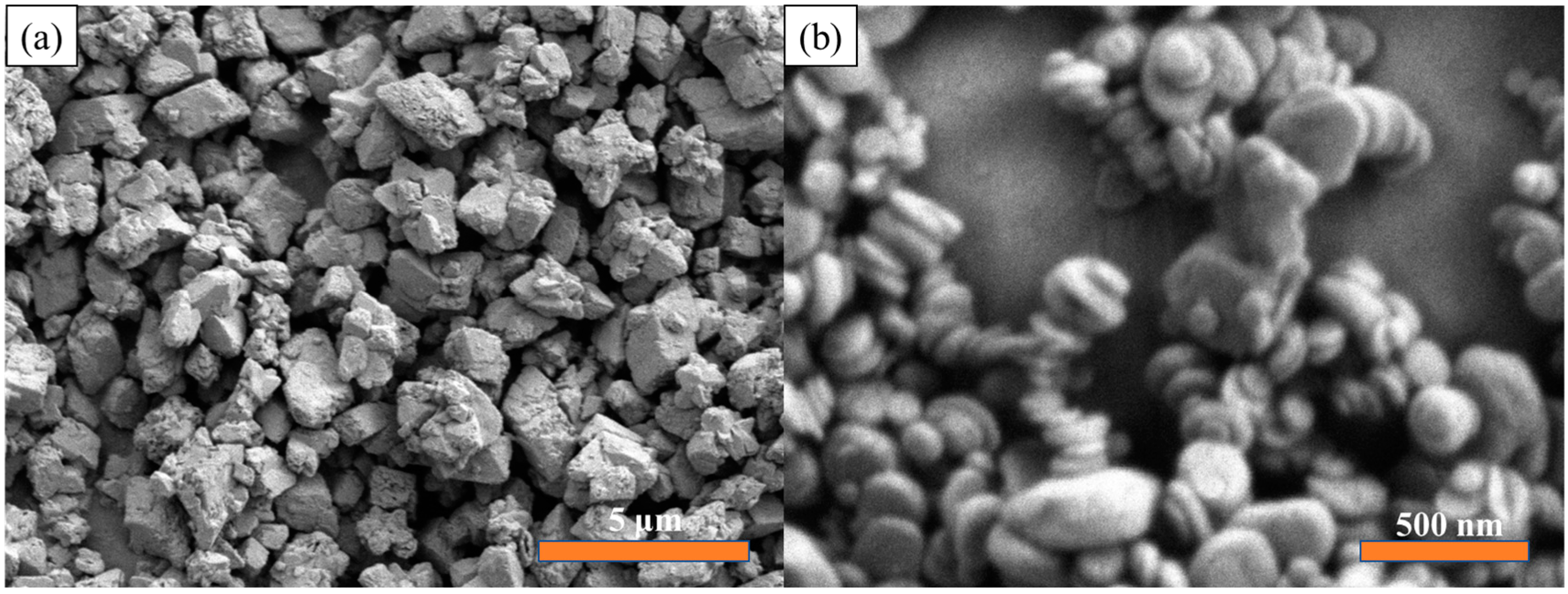
2.2. Fabrication of Ba0.6Sr0.4TiO3 Nanoparticles

To prepare Ba0.6Sr0.4TiO3 nanoparticles, Ba(NO3)2, tetrabutyl titanate, and Sr(NO3)2 were used as the main raw materials, oxalic acid dihydrate was used as precipitant, and a mixed solution (deionized water and ethanol) was used as solvent. The specific experimental steps were as follows: A beaker was poured with 0.1 mol of HC2O4·2H2O. Amounts of 150 mL of distilled water and 50 mL of absolute ethanol were measured as solvents. Under the condition of heating in a water bath, the liquid in the beaker was stirred, so that HC2O4·2H2O was completely dissolved, and the mixed solution was marked as Mixture A. An amount of 0.05 mol of tetrabutyl titanate was dissolved in 100 mL of absolute ethanol, heated and stirred to mix well, and this mixed solution was marked as Mixture B. Amounts of 0.02 mol Sr(NO3)2 and 0.03 mol Ba(NO3)2 were dissolved in 100 mL of distilled water, heated and stirred until Sr(NO3)2 and 0.03 mol Ba(NO3)2 were completely dissolved, and the mixed solution was marked as a Mixture C. Mixture B and Mixture A were mixed, and after being stirred evenly, ammonia water was added to adjust the pH to about 3.5 to obtain Mixture D. Under the condition of heating to 80 °C in a water bath, Mixture C was slowly added dropwise to Mixture D, and then stirred for 2 h to separate the compounds. After the complete reaction, the resulting mixed solution was aged for 24 h. After being aged for 24 h, the precursor of Ba0.6Sr0.4TiO3 powder was centrifuged and washed. Then, the precursor of Ba0.6Sr0.4TiO3 powder was dried in a drying oven at 100 °C for 6 h and calcined in a muffle furnace at 800 °C. After the Ba0.6Sr0.4TiO3 powder was ground by a ball mill for 12 h, the Ba0.6Sr0.4TiO3 nanopowders were successfully prepared. A schematic diagram of the fabrication of Ba0.6Sr0.4TiO3 nanoparticles is shown in Figure S1.

2.3. Preparation of Ba0.6Sr0.4TiO3@DA Nanoparticles

First, the surface of BST was treated with hydroxyl groups. The Ba0.6Sr0.4TiO3 nanopowders were dispersed in a mixed solution (ethanol and water) with a ratio of ethanol to water of 1:1, stirred and ultrasonically dispersed for 4 h, and dried for 12 h. Then, the treated Ba0.6Sr0.4TiO3 nanopowders were added to a dopamine buffer solution (dopamine hydrochloride), and Mixture E was obtained by ultrasonic stirring for 10 h. Finally, Mixture E was centrifuged and dried, and the Ba0.6Sr0.4TiO3@DA nanoparticles were successfully obtained. Chemical surface modification of inorganic nanoparticles can improve the uniformity of nanocomposites [37]. The distribution of the diameters of Ba0.6Sr0.4TiO3 nanoparticles is shown in Figure S2. The diameter of the filler is mainly distributed in the 800 nm attachment. The TEM images of Ba0.6Sr0.4TiO3@DA NPs are shown in Figure S3.

2.4. Preparation of Boron Nitride Nanosheets

Boron nitride nanosheets (BNNS) were obtained by exfoliating hexagonal boron nitride powder (h-BN) by the chemical solvent ultrasonic method. The preparation process is shown in Figure 1. An amount of 1 g of hexagonal boron nitride powder was accurately weighed into a centrifuge tube, and absolute ethanol was added to the centrifuge tube. The centrifuge tube was placed under the ultrasonic probe, the height of the ultrasonic probe was adjusted, and the probe made as deep as possible toward the bottom of the centrifuge tube, without touching the wall of the centrifuge tube. The centrifuge tube mouth was sealed with parafilm to prevent solvent volatilization during ultrasonication. The power of the sonicator was set to 200 W. The mixture in the centrifuge tube was centrifuged after 2 h of uninterrupted operation of the needle tip sonicator. After centrifugation, the supernatant was discarded and the bottom pellet collected. The obtained precipitate was placed in a vacuum drying oven at 60 °C for 24 h to obtain boron nitride nanosheets (BNNS).

2.5. Preparation of Sandwich-Structured Composite Films

The sandwich-structured composite film material was prepared by way of layer-by-layer solution casting. The fabrication process of the composite films is shown in Figure 1. In this paper, 5 wt.% PVDF/BNNS-0 vol.% PVDF/Ba0.6Sr0.4TiO3@DA-5 wt.% PVDF/BNNS can be abbreviated as B0B, 5 wt.% PVDF/BNNS-1 vol.% PVDF/Ba0.6Sr0.4TiO3@DA-5 wt.% PVDF/BNNS can be abbreviated as B1B, 5 wt.% PVDF/BNNS-2 vol.% PVDF/Ba0.6Sr0.4TiO3@DA-5 wt.% PVDF/BNNS can be abbreviated as B2B, and 5 wt.% PVDF/BNNS-3 vol.% PVDF/Ba0.6Sr0.4TiO3@DA-5 wt.% PVDF/BNNS can be abbreviated as B3B.

2.6. Characterization

In this study, the phase structures of inorganic nanoparticles and nanocomposites were analyzed using an X-ray diffractometer (XRD). The model of this X-ray diffractometer is Rigaku D/max-2200. The microstructure of the samples was analyzed by field emission scanning electron microscopy (FEI). The composition of the samples was analyzed using an energy dispersive spectrometer (EDS). The specific sample preparation method is as follows: For powder SEM sample preparation, the powder was dissolved in ethanol, and ultrasonic shock was performed for 30 min. The upper liquid was taken from the capillaries on the aluminum foil, dried and sprayed with gold, and observed. For sandwich-structured composite material SEM sample preparation, the composite material was placed in liquid nitrogen for quenching, the quenched sample was placed on the sample table, and the microstructure was observed after drying and spraying gold. Gold in a circle shape with a diameter of 1 cm was sputtered onto both sides of the composite films as the electrodes for the dielectric characterization. The dielectric constant and loss of the composite films were characterized using an Agilent E4980A. An Agilent precision impedance analyzer (E4980A, Agilent, Santa Clara, CA, USA) was also used for AC conductivity tests. The test frequency was 20 Hz-2 MHz, the temperature was room temperature, and the measurement circuit adopted a four-terminal double-lead mode. The AC conductivity of the sample was obtained by using the instrument to test the impedance of the sample. Gold in a circle shape with a diameter of 2 mm was sputtered onto both sides of the composite films as the electrodes for the characterization of ferroelectric parametron properties. The D-E hysteresis loops of the composite films were determined using a Radiant Premier II. A breakdown strength test was performed using a Precision Multiferroic ferroelectric tester from Radiant Technologies, USA. The test temperature range was room temperature, and the test frequency was 10 Hz.

3. Results and Discussion

It can be seen from Figure 2a that BNNS mainly has a strong diffraction peak at 27°, which corresponds to the diffraction position of the (002) crystal plane. The peak is strong and sharp, indicating that the crystals of boron nitride nanosheets obtained after exfoliation are still highly ordered. The positions of the XRD peaks of the BST nanoparticles in Figure 2a are in perfect agreement with the standard Ba0.6Sr0.4TiO3 card, which proves that the perovskite-structured barium strontium titanate was successfully synthesized. No other peaks were generated in the XRD spectrum, indicating that the prepared BST nanoparticles were of high purity.
In order to analyze the phase structure of the sandwich-structured nanocomposites, the sandwich-structured nanocomposites with contents of 0 vol.%, 1 vol.%, 2 vol.%, and 3 vol.% of BST nanoparticles in the interlayer were characterized by X-ray diffraction, as shown in Figure 2b. The nano-nanocomposite material also appeared with a new diffraction peak, that is, the characteristic diffraction peak of BNNS at 27°, indicating that the crystalline structure of PVDF and BNNS was not destroyed in the composite of PVDF and BNNS. As can be seen from Figure 2b, for the prepared three-layer composite material, in addition to the diffraction peaks of PVDF, the characteristic diffraction peaks belonging to BST and the characteristic diffraction peaks of BNNS appear at the same time. It was demonstrated that sandwich-structured nanocomposite films were successfully prepared without significant damage to the crystallinity of BNNS and BST. The crystalline phase of PVDF in sandwich composites is mainly composed of the non-polar α phase and γ phase [38], in which the γ phase mainly originates from the quenching process of the composite film instantaneously transferred from a high temperature of 200 °C to ice water. The existence of nonferroelectric α and γ phases is beneficial to the dipole rotation of the composite film during the removal of the electric field, which helps to reduce the remnant polarization.
The SEM results of Ba0.6Sr0.4TiO3 NPs are shown in Figure 3a. The average diameter of Ba0.6Sr0.4TiO3 NPs is 500 nm, which means that the Ba0.6Sr0.4TiO3 NPs used in this paper can provide larger interfacial polarization and a higher dielectric constant. At the same time, they can also meet the high dielectric constant filler requirements for constructing high dielectric constant layers in “sandwich” composite dielectrics. The microscopic morphology of BNNS can be seen from the SEM image in Figure 3b. BNNS exhibits a lamellar structure, and the size in the plane direction is about 100 nm. The good dispersibility of BNNS is attributed to the strong polarity caused by the B-N chemical bond on the molecular plane, which not only helps its uniform dispersion in DMF but also its uniform distribution in the polar polymer matrix.
A schematic diagram of the sandwich-structured PVDF-based nanocomposite dielectric material is shown in Figure 4. Figure 4a,d,g,j are a cross-sectional scan of the sandwich-structured nanocomposite. The contents of BST NPs in the middle layer are 0 vol.%, 1 vol.%, 2 vol.%, and 3 vol.%, respectively. It can be seen from the cross-sectional scan that the nanofillers have good dispersibility in the polymer matrix of each layer. There are no defects such as separation or voids at the interface between different layers, indicating that the preparation process is good. There is no introduction of defects such as air, which is beneficial to the improvement in the dielectric properties of the three-layer structure material. The layered structure could not be clearly observed from the quenched cross-section of the sandwich composite film, so we performed an EDS surface scanning test on the sandwich composite. The distribution of the main elements (N, Ti) in the material is clearly observed, and the results are shown in Figure 4b–f,h,i,k,l, showing a uniform layered distribution. The Ti element is concentrated in the middle part of the sandwich composite film. The N element (BNNS) is dispersed on both sides of the sandwich composite film. With the increasing volume percentage of Ba0.6Sr0.4TiO3 NPs in the interlayer, the Ti element is more and more enriched, which is completely consistent with the original design of the experiment.
The relationship between the dielectric constant and the dielectric loss as a function of frequency is characterized by the sandwich structure composite when the content of Ba0.6Sr0.4TiO3 NPs in the intermediate layer changes, as shown in Figure 5. As the content of Ba0.6Sr0.4TiO3 NPs in the interlayer gradually increased, the dielectric constant of the sandwich structure material also gradually increased. At 1000 Hz, the dielectric constant of Ba0.6Sr0.4TiO3 NPs with 3 vol.% volume fraction added is 10.71. The increase in the dielectric constant is mainly due to the high dielectric constant of Ba0.6Sr0.4TiO3 NPs. It can be seen from Figure 5b that although the content of Ba0.6Sr0.4TiO3 NPs in the interlayer is added to 3 vol.%, the dielectric loss of the sandwich composites is always maintained at a low level (tan δ < 0.04).
Figure 6 shows the AC conductivity of sandwich-structured composite films. It can be seen from Figure 6a that the AC conductivities of the sandwich-structured composites are very low because BNNS can hinder the injection of charges at the electrodes and hinder the transport of charges in the polymer matrix. Low AC conductivity can reduce the leakage current of sandwich composites under a high field. On the other hand, the smaller conductivity loss of the sandwich composite will reduce the remanent polarization and increase the breakdown field strength of the composite. As shown in Figure 6b, the AC conductivity of the sandwich-structured composites exhibits a strong frequency dependence, which increases nonlinearly with increasing frequency. The conductivity of sandwich-structured composites increased with the increase in Ba0.6Sr0.4TiO3 NPs loading in the middle layer. However, the increase in conductivity of the sandwich-structured composites did not change by an order of magnitude. All sandwich-structured composites still have good insulating properties.
The electrical displacement and electric field intensity curves were tested for pure PVDF polymer and sandwich nanocomposites. Figure 7a shows the D-E curve measured at an electric field strength of 200 kV/mm. It can be seen from Figure 7a that the maximum electrical displacement value of B0B at 200 kV/mm is only 3.72027 μC/cm2, which is due to the low dipole polarizability caused by PVDF with a low dielectric constant. With the increase in the content of Ba0.6Sr0.4TiO3 NPs in the interlayer, the maximum electrical displacement value gradually increased. At the addition of 3 vol.% Ba0.6Sr0.4TiO3 NPs, the maximum electrical displacement is 5.86947 μC/cm2, which is due to the gradual increase in the dielectric constant of the sandwich composites with the increase in Ba0.6Sr0.4TiO3 NPs. The remanent polarization of the sandwich structure also increases with the content of Ba0.6Sr0.4TiO3 NPs. At 0 vol.% Ba0.6Sr0.4TiO3 NP content, the remnant polarization is 0.31132 μC/cm2. With the gradual increase in the Ba0.6Sr0.4TiO3 NP content in the interlayer, the remanent polarization also increases gradually. At 1 vol.% Ba0.6Sr0.4TiO3 NP content, the remnant polarization is 0.39749 μC/cm2. When the addition of Ba0.6Sr0.4TiO3 NPs was 3 vol.%, the remnant polarization also reached the maximum value of 0.80512 μC/cm2, and the overall low remnant polarization of the sandwich composites is mainly attributed to the hindering effect of the outer BNNS. The existence of the outer layer of BNNS can effectively hinder the injection of electrons, thereby reducing the leakage current value of the material, which is also reflected in the AC conductivity of the composite material.
The D-E curve of the composite under the maximum electric field is shown in Figure 7b. It can be seen from Figure 7b that the sandwich-structured composite exhibits a nonlinear (ferroelectric) response to the external electric field at high fields, which is mainly due to the inherent ferroelectricity of PVDF and Ba0.6Sr0.4TiO3 NPs. The breakdown field strength of the prepared sandwich-structured nanocomposites also was analyzed, and the two-parameter Weibull distribution method was used for fitting [39].
P E = 1 exp E E b β
In the above Formula (2), the value of P(E) is the cumulative failure probability of the electric field, and Eb and E, respectively, refer to the breakdown field strength and the test breakdown field strength when the cumulative failure probability is 63.2% [40]. β is a shape parameter related to the discreteness of the experimental data. A high β value indicates that the nanocomposites are of high quality. The Weibull distribution diagram of the breakdown field strength is shown in Figure 7c, and Figure 7d is the variation of the Weibull breakdown field strength value with the content of Ba0.6Sr0.4TiO3 NPs in the intermediate layer. It can be seen from the figure that with the increase in Ba0.6Sr0.4TiO3 NPs in the sandwich structure material, the breakdown field strength of the three-layer composite material increases first and then decreases. When the Ba0.6Sr0.4TiO3 NP content was increased to 1 vol.%, the breakdown field strength of the three-layer composite was the largest, at 310 kV/mm. As the content of Ba0.6Sr0.4TiO3 NPs continued to increase, the breakdown field strength of the composites gradually decreased. With the highest addition of Ba0.6Sr0.4TiO3 NPs (3 vol.%), the breakdown field strength of the composite dropped to 210 kV/mm. With the increase in the content of Ba0.6Sr0.4TiO3 NPs in the middle layer, the sandwich structure composites showed a trend of first increasing and then decreasing: One reason is that after the content of Ba0.6Sr0.4TiO3 NPs exceeds 1 vol.%, the volume fraction of nanofillers may exceed the ideal percentage content that the polymer matrix can accommodate when the inorganic fillers are uniformly distributed. Too much filler leads to uneven distribution of Ba0.6Sr0.4TiO3 NPs in the PVDF matrix, or even agglomeration, which affects the improvement in the breakdown field strength. Another reason is the voltage divider between the different layers, which has been similarly reported in the work of others. In sandwich-structured nanocomposites composed of different dielectric layers, the electric field strength of the low-k layers is higher than that of the high-k layers. For the sandwich-structured nanocomposites in this study, the outer layer PVDF/BNNS can withstand higher electric field strengths than the middle layer PVDF/Ba0.6Sr0.4TiO3 NPs with a high dielectric constant due to its lower dielectric constant. When the overall three-layer composite is under the same voltage, with the increase in the Ba0.6Sr0.4TiO3 NP content in the intermediate layer, the dielectric constant of the intermediate layer increases continuously, so the voltage shared by the intermediate layer gradually decreases. When the content of Ba0.6Sr0.4TiO3 NPs is less than 1 vol.%, the intermediate layer will be broken down first due to the existence of Ba0.6Sr0.4TiO3 NPs, and the withstand voltage characteristics will be reduced. When the content of Ba0.6Sr0.4TiO3 NPs was greater than 1 vol.%, the voltage obtained by the outer layer continued to increase. Although the outer two layers have improved withstand voltage characteristics due to the presence of BNNS, the pressure drop has exceeded the withstand voltage range, causing the outer two layers to be broken down. The breakdown field strength of the final sandwich nanocomposite reaches the maximum value when the Ba0.6Sr0.4TiO3 NP content is 1 vol.%.
In addition to the above-mentioned breakdown field strength and polarization properties, Dm-Dr also plays an important role in the performance of dielectric energy storage. Thus, the Dm, Dr, and Dm-Dr of the complex were also calculated from the D-E curve, as shown in Figure 7a. Compared to B0B, B2B, and B3B, the Dm of the sandwich-structured composites is significantly improved due to the significantly higher breakdown field strength of B1B. At the same time, the Dr of B1B is kept at a very low level. Lower Dr is beneficial for high discharge energy density because it means that the stored energy can be effectively released during the discharge process. With the increase in Ba0.6Sr0.4TiO3 NP content, the Dm-Dr of sandwich-structured composites first increased and then decreased. It should be noted that B1B exhibited the highest Dm-Dr (6.2 C/cm2). The greatly improved breakdown field strength and Dm-Dr in B1B composites may lead to simultaneous improvements in discharge energy density and energy efficiency.
In the above analysis, the Sawyer-Tower circuit was used to test the discharge energy density and charge-discharge efficiency of the sandwich structure composite at room temperature. The discharge energy density and energy efficiency of the sandwich-structured composites can be calculated from the D-E curves, and the results are shown in Figure 8b.
η = U d U
In Formula (3), Ud is the released energy density of the material, and U is the stored energy density of the material [41]. For a more intuitive comparison, Figure 8b presents detailed data on the discharge energy density, charge energy density, and charge-discharge energy efficiency under the breakdown electric field for the four sandwich-structured composites. Although the maximum electrical displacement of B3B is larger than that of B2B, the discharge energy density of B2B is higher due to the higher breakdown field strength of B2B. At the same time, the higher Dr of B2B also leads to a significant drop in its energy efficiency. B1B exhibited the highest discharge energy density of 8.9 J/cm3 at a breakdown field of 310 kV/mm, an improvement over the energy storage performance data of PVDF obtained under the same conditions, which is shown in Figure S4. Although the energy efficiency of the composite gradually decreased with the electric field due to the ferroelectricity of PVDF and Ba0.6Sr0.4TiO3 NPs, the energy efficiency of B1B remained at 76% at an electric field of 310 kV/mm. Taking the discharge energy density and energy efficiency into consideration, B1B exhibits the best energy storage performance among a series of sandwich-structured composite dielectrics.

4. Conclusions

In this study, PVDF-based sandwich structure nanocomposites were prepared by a layer-by-layer solution casting method using PVDF as the matrix. In the sandwich-structured nanocomposites, 5 wt.% PVDF/BNNS was used as the outer layer of the three-layer structure, and 0 vol.%, 1 vol.%, 2 vol.%, and 3 vol.% PVDF/Ba0.6Sr0.4TiO3 NPs were used as the middle layer, respectively. The dispersion of BNNS by ultrasound and the coating of Ba0.6Sr0.4TiO3 NPs by dopamine promote the uniform distribution of nanofillers in the polymer matrix. SEM analysis showed that the layers of the sandwich-structured nanocomposites are tightly bonded to the other layers. EDS showed that the distribution of layers is very clear and the BNNS and Ba0.6Sr0.4TiO3 NPs are well dispersed. XRD analysis showed that the composites were mainly composed of non-polar α-phase and γ-phase, which was conducive to the rotation of the electric dipoles of the composites during the discharge process. The breakdown field strength of the sandwich structure composite with 1 vol.% PVDF/Ba0.6Sr0.4TiO3 in the middle layer reaches 310 Kv/mm. D-E curve analysis shows that the maximum discharge energy density of the sandwich-structured composite is 8.9, and the maximum discharge energy efficiency is 76%.

Supplementary Materials

The following supporting information can be downloaded at: https://www.mdpi.com/article/10.3390/polym15173642/s1, Figure S1. Schematic diagram of fabrication of Ba0.6Sr0.4TiO3 nanoparticles; Figure S2. The distribution of diameter of Ba0.6Sr0.4TiO3 nanoparticles; Figure S3. TEM images of Ba0.6Sr0.4TiO3@DA NPs; Figure S4. The energy storage performance data of PVDF obtained under the same conditions.

Author Contributions

Conceptualization, Z.Y. and Z.W.; methodology, Z.Y. and Z.W.; software, Z.W.; validation, Z.Y. and Z.W.; formal analysis, Z.Y. and Z.W.; investigation, Z.Y.; resources, Z.W.; data curation, Z.Y., D.W. and Y.X.; writing—original draft preparation, Z.Y.; writing—review and editing, Z.Y., Z.W., D.W. and Y.X.; supervision, Z.W.; project administration, Z.Y., Z.W., D.W. and Y.X.; funding acquisition, Z.W. All authors have read and agreed to the published version of the manuscript.

Funding

The present work was supported by the National Natural Science Foundation of China (52102139), the National Key Research and Development Program of Shaanxi Province (2021GY-224), the Key Laboratory of Engineering Dielectrics and Its Application (Harbin University of Science and Technology), the Ministry of Education (KFM202106), and the Graduate Innovation Fund of Shaanxi University of Science and Technology.

Institutional Review Board Statement

Not applicable.

Informed Consent Statement

Not applicable.

Data Availability Statement

The data presented in this study are available on request from the corresponding author.

Conflicts of Interest

The authors declare that they have no conflict of interest.

References

  1. Chu, B.J.; Zhou, X.; Ren, K.L.; Neese, B.; Lin, M.R.; Wang, Q.; Bauer, F.; Zhang, Q.M. A dielectric polymer with high electric energy density and fast discharge speed. Science 2006, 313, 334–336. [Google Scholar] [CrossRef] [PubMed]
  2. Shen, X.; Zheng, Q.; Kim, J.-K. Rational design of two-dimensional nanofillers for polymer nanocomposites toward multifunctional applications. Prog. Mater. Sci. 2021, 115, 100708. [Google Scholar] [CrossRef]
  3. Chen, J.; Wang, Y.; Yuan, Q.; Xu, X.; Niu, Y.; Wang, Q.; Wang, H. Multilayered ferroelectric polymer films incorporating low-dielectric-constant components for concurrent enhancement of energy density and charge-discharge efficiency. Nano Energy 2018, 54, 288–296. [Google Scholar] [CrossRef]
  4. Chi, Q.; Zhou, Y.; Feng, Y.; Cui, Y.; Zhang, Y.; Zhang, T.; Chen, Q. Excellent energy storage performance of polyetherimide filled by oriented nano fibers with optimized diameters. Mater. Today Energy 2020, 18, 100516. [Google Scholar] [CrossRef]
  5. Martins, P.; Lopes, A.C.; Lanceros-Mendez, S. Electroactive phases of poly(vinylidene fluoride): Determination, processing and applications. Prog. Polym. Sci. 2014, 39, 683–706. [Google Scholar] [CrossRef]
  6. Feng, Q.-K.; Zhong, S.-L.; Pei, J.-Y.; Zhao, Y.; Zhang, D.-L.; Liu, D.-F.; Zhang, Y.-X.; Dang, Z.-M. Recent Progress and Future Prospects on All-Organic Polymer Dielectrics for Energy Storage Capacitors. Chem. Rev. 2022, 122, 3820–3878. [Google Scholar] [CrossRef]
  7. Yi, Z.; Wang, Z.; Nian, W.; Wang, T.; Chen, H.; Cheng, Z. High Energy Storage Density of Sandwich-Structured Na0.5Bi0.5TiO3/PVDF Nanocomposites Enhanced by Optimizing the Dimensions of Fillers. ACS Appl. Energy Mater. 2021, 4, 13528–13537. [Google Scholar] [CrossRef]
  8. Jiang, J.; Shen, Z.; Cai, X.; Qian, J.; Dan, Z.; Lin, Y.; Liu, B.; Nan, C.-W.; Chen, L.; Shen, Y. Polymer Nanocomposites with Interpenetrating Gradient Structure Exhibiting Ultrahigh Discharge Efficiency and Energy Density. Adv. Energy Mater. 2019, 9, 1803411. [Google Scholar] [CrossRef]
  9. Khanchaitit, P.; Han, K.; Gadinski, M.R.; Li, Q.; Wang, Q. Ferroelectric polymer networks with high energy density and improved discharged efficiency for dielectric energy storage. Nat. Commun. 2013, 4, 2845. [Google Scholar] [CrossRef]
  10. Sun, S.; Shi, Z.; Liang, L.; Li, T.; Zhang, S.; Xu, W.; Han, M.; Zhang, M. Simultaneous Realization of Significantly Enhanced Breakdown Strength and Moderately Enhanced Permittivity in Layered PMMA/P(VDF-HFP) Nanocomposites via Inserting an Al2O3/P(VDF-HFP) Layer. J. Phys. Chem. C 2021, 125, 22379–22387. [Google Scholar] [CrossRef]
  11. Diao, C.; Liu, H.; Zheng, H.; Yao, Z.; Iqbal, J.; Cao, M.; Hao, H. Enhanced energy storage properties of BaTiO3 thin films by Ba0.4Sr0.6TiO3 layers modulation. J. Alloys Compd. 2018, 765, 362–368. [Google Scholar] [CrossRef]
  12. Chen, Q.; Shen, Y.; Zhang, S.H.; Zhang, Q.M. Polymer-Based Dielectrics with High Energy Storage Density. Annu. Rev. Mater. Res. 2015, 45, 433–458. [Google Scholar] [CrossRef]
  13. Pan, Z.; Yao, L.; Zhai, J.; Yao, X.; Chen, H. Interfacial Coupling Effect in Organic/Inorganic Nanocomposites with High Energy Density. Adv. Mater. 2018, 30, 1705662. [Google Scholar] [CrossRef] [PubMed]
  14. Hu, J.; Zhang, S.; Tang, B. 2D filler-reinforced polymer nanocomposite dielectrics for high-k dielectric and energy storage applications. Energy Storage Mater. 2021, 34, 260–281. [Google Scholar] [CrossRef]
  15. Li, H.; Ren, L.; Zhou, Y.; Yao, B.; Wang, Q. Recent progress in polymer dielectrics containing boron nitride nanosheets for high energy density capacitors. High Volt. 2020, 5, 365–376. [Google Scholar] [CrossRef]
  16. Hu, H.; Zhang, F.; Luo, S.; Chang, W.; Yue, J.; Wang, C.-H. Recent advances in rational design of polymer nanocomposite dielectrics for energy storage. Nano Energy 2020, 74, 104844. [Google Scholar] [CrossRef]
  17. Cui, Y.; Zhang, T.; Feng, Y.; Zhang, C.; Chi, Q.; Zhang, Y.; Chen, Q.; Wang, X.; Lei, Q. Excellent energy storage density and efficiency in blend polymer-based composites by design of core-shell structured inorganic fibers and sandwich structured films. Compos. Part B Eng. 2019, 177, 107429. [Google Scholar] [CrossRef]
  18. Li, Q.; Zhang, G.Z.; Liu, F.H.; Han, K.; Gadinski, M.R.; Xiong, C.X.; Wang, Q. Solution-processed ferroelectric terpolymer nanocomposites with high breakdown strength and energy density utilizing boron nitride nanosheets. Energy Environ. Sci. 2015, 8, 922–931. [Google Scholar] [CrossRef]
  19. Pan, Z.; Zhai, J.; Shen, B. Multilayer hierarchical interfaces with high energy density in polymer nanocomposites composed of BaTiO3@TiO2@Al2O3 nanofibers. J. Mater. Chem. A 2017, 5, 15217–15226. [Google Scholar] [CrossRef]
  20. Li, Y.; Zhou, Y.; Zhu, Y.; Cheng, S.; Yuan, C.; Hu, J.; He, J.; Li, Q. Polymer nanocomposites with high energy density and improved charge-discharge efficiency utilizing hierarchically-structured nanofillers. J. Mater. Chem. A 2020, 8, 6576–6585. [Google Scholar] [CrossRef]
  21. Bai, H.; Zhu, K.; Wang, Z.; Shen, B.; Zhai, J. 2D Fillers Highly Boost the Discharge Energy Density of Polymer-Based Nanocomposites with Trilayered Architecture. Adv. Funct. Mater. 2021, 31, 2102646. [Google Scholar] [CrossRef]
  22. Pan, Z.; Ding, Q.; Yao, L.; Huang, S.; Xing, S.; Liu, J.; Chen, J.; Zhai, J. Simultaneously enhanced discharge energy density and efficiency in nanocomposite film capacitors utilizing two-dimensional NaNbO3@Al2O3 platelets. Nanoscale 2019, 11, 10546–10554. [Google Scholar] [CrossRef] [PubMed]
  23. Sun, L.; Shi, Z.; He, B.; Wang, H.; Liu, S.; Huang, M.; Shi, J.; Dastan, D.; Wang, H. Asymmetric Trilayer All-Polymer Dielectric Composites with Simultaneous High Efficiency and High Energy Density: A Novel Design Targeting for Advanced Energy Storage Capacitors. Adv. Funct. Mater. 2021, 31, 2100280. [Google Scholar] [CrossRef]
  24. Cheng, Y.; Pan, Z.; Bai, H.; Chen, H.; Yao, L.; Ding, X.; Shi, S.; Liu, J.; Xie, Z.; Xu, J.; et al. Two-Dimensional Fillers Induced Superior Electrostatic Energy Storage Performance in Trilayered Architecture Nanocomposites. ACS Appl. Mater. Interfaces 2022, 14, 8448–8457. [Google Scholar] [CrossRef] [PubMed]
  25. Chi, Q.; Ma, T.; Zhang, Y.; Chen, Q.; Zhang, C.; Cui, Y.; Zhang, T.; Lin, J.; Wang, X.; Lei, Q. Excellent Energy Storage of Sandwich-Structured PVDF-Based Composite at Low Electric Field by Introduction of the Hybrid CoFe2O4@BZT-BCT Nanofibers. ACS Sustain. Chem. Eng. 2018, 6, 403–412. [Google Scholar] [CrossRef]
  26. Sun, Q.; Wang, J.; Sun, H.; He, L.; Zhang, L.; Mao, P.; Zhang, X.; Kang, F.; Wang, Z.; Kang, R.; et al. Simultaneously enhanced energy density and discharge efficiency of layer-structured nanocomposites by reasonably designing dielectric differences between BaTiO3@SiO2/PVDF layers and BNNSs/PVDF-PMMA layers. Compos. Part A Appl. Sci. Manuf. 2021, 149, 106546. [Google Scholar] [CrossRef]
  27. Hu, P.H.; Shen, Y.; Guan, Y.H.; Zhang, X.H.; Lin, Y.H.; Zhang, Q.M.; Nan, C.W. Topological-Structure Modulated Polymer Nanocomposites Exhibiting Highly Enhanced Dielectric Strength and Energy Density. Adv. Funct. Mater. 2014, 24, 3172–3178. [Google Scholar] [CrossRef]
  28. Li, Z.; Shen, Z.; Yang, X.; Zhu, X.; Zhou, Y.; Dong, L.; Xiong, C.; Wang, Q. Ultrahigh charge-discharge efficiency and enhanced energy density of the sandwiched polymer nanocomposites with poly(methyl methacrylate) layer. Compos. Sci. Technol. 2021, 202, 108591. [Google Scholar] [CrossRef]
  29. Xu, W.; Liu, J.; Chen, T.; Jiang, X.; Qian, X.; Zhang, Y.; Jiang, Z.; Zhang, Y. Bioinspired Polymer Nanocomposites Exhibit Giant Energy Density and High Efficiency at High Temperature. Small 2019, 15, 1901582. [Google Scholar] [CrossRef]
  30. Li, Z.; Liu, F.; Li, H.; Ren, L.; Dong, L.; Xiong, C.; Wang, Q. Largely enhanced energy storage performance of sandwich-structured polymer nanocomposites with synergistic inorganic nanowires. Ceram. Int. 2019, 45, 8216–8221. [Google Scholar] [CrossRef]
  31. Zhu, D.; Zhao, J.; Yang, Z.; Guo, H.; Gao, L. Graphene Oxide/Polyimide Composites with High Energy Storage Density Based on Multilayer Structure. Chem. J. Chin. Univ. Chin. 2021, 42, 2694–2700. [Google Scholar] [CrossRef]
  32. Wang, Y.; Wang, L.; Yuan, Q.; Niu, Y.; Chen, J.; Wang, Q.; Wang, H. Ultrahigh electric displacement and energy density in gradient layer-structured BaTiO3/PVDF nanocomposites with an interfacial barrier effect. J. Mater. Chem. A 2017, 5, 10849–10855. [Google Scholar] [CrossRef]
  33. Huang, Y.H.; Wang, J.J.; Yang, T.N.; Wu, Y.J.; Chen, X.M.; Chen, L.Q. A thermodynamic potential, energy storage performances, and electrocaloric effects of Ba1-xSrxTiO3 single crystals. Appl. Phys. Lett. 2018, 112, 102901. [Google Scholar] [CrossRef]
  34. Chen, S.; Xu, R.; Liu, J.; Zou, X.; Qiu, L.; Kang, F.; Liu, B.; Cheng, H.-M. Simultaneous Production and Functionalization of Boron Nitride Nanosheets by Sugar-Assisted Mechanochemical Exfoliation. Adv. Mater. 2019, 31, 1804810. [Google Scholar] [CrossRef] [PubMed]
  35. Feng, M.; Feng, Y.; Zhang, T.; Li, J.; Chen, Q.; Chi, Q.; Lei, Q. Recent Advances in Multilayer-Structure Dielectrics for Energy Storage Application. Adv. Sci. 2021, 8, 2102221. [Google Scholar] [CrossRef]
  36. Chen, J.; Liu, J.; Cai, L.; Wang, C.; Liu, L.; Yang, Q.; Xiong, C. Incorporation of elaborately Synthesized BNNSs by a mild mechanical stirring process for the concurrent enhancement of thermal conductivity and dielectric breakdown strength of PVDF. Compos. Sci. Technol. 2020, 200, 108381. [Google Scholar] [CrossRef]
  37. Marwat, M.A.; Ma, W.; Fan, P.; Elahi, H.; Samart, C.; Nan, B.; Tan, H.; Salamon, D.; Ye, B.; Zhang, H. Ultrahigh energy density and thermal stability in sandwich-structured nanocomposites with dopamine@Ag@BaTiO3. Energy Storage Mater. 2020, 31, 492–504. [Google Scholar] [CrossRef]
  38. Nakafuku, C.; Yasuniwa, M. Melting and Crystallization of Poly(vinylidene fluoride) in the Blend with Poly(methyl methacrylate) under High Pressure. Polym. J. 1987, 19, 845–853. [Google Scholar] [CrossRef]
  39. Zhang, Y.; Zhang, C.; Feng, Y.; Zhang, T.; Chen, Q.; Chi, Q.; Liu, L.; Wang, X.; Lei, Q. Energy storage enhancement of P(VDF-TrFE-CFE)-based composites with double-shell structured BZCT nanofibers of parallel and orthogonal configurations. Nano Energy 2019, 66, 104195. [Google Scholar] [CrossRef]
  40. Zhu, L.; Zhang, Y.; Xu, W.; Zhu, X.; Niu, S.; Zhang, Y.; Jiang, Z. Crosslinked polyetherimide nanocomposites with superior energy storage achieved via trace Al2O3 nanoparticles. Compos. Sci. Technol. 2022, 223, 109421. [Google Scholar] [CrossRef]
  41. Wang, C.; He, G.; Chen, S.; Luo, H.; Yang, Y.; Zhang, D. Achieving high breakdown strength and energy density in all-organic sandwich-structured dielectrics by introducing polyacrylate elastomers. J. Mater. Chem. A 2022, 10, 9103–9113. [Google Scholar] [CrossRef]
Figure 1. Schematic diagram of the preparation process of nanocomposite films. (a) Preparation of nano-filler, (b) Preparation of boron nitride nanosheets, (c) Preparation of mixed solution for tape casting, (d) The steps of casting method.
Polymers 15 03642 g001
Figure 2. (a) XRD patterns of as-prepared Ba0.6Sr0.4TiO3 NPs and as-prepared BNNS. (b) XRD patterns of as-prepared different nanocomposites.
Polymers 15 03642 g002
Figure 3. The SEM of (a) Ba0.6Sr0.4TiO3 NPs and (b) BNNS.
Polymers 15 03642 g003
Figure 4. (a,d,g,j) Cross-sectional SEM image of the sandwich-structured nanocomposite with 0 vol.%, 1 vol.%, 2 vol.%, and 3 vol.% Ba0.6Sr0.4TiO3 NPs in the central layer, respectively. (b,e,h,k) EDS element (N) distribution of the sandwich-structured nanocomposite with 0 vol.%, 1 vol.%, 2 vol.%, and 3 vol.% Ba0.6Sr0.4TiO3 NPs in the central layer, respectively. (c,f,i,l) EDS element (Ti) of the sandwich-structured nanocomposite with 0 vol.%, 1 vol.%, 2 vol.%, and 3 vol.% Ba0.6Sr0.4TiO3 NPs in the central layer, respectively.
Polymers 15 03642 g004
Figure 5. Frequency dependence of (a) dielectric constant and (b) dielectric loss of composites at room temperature.
Polymers 15 03642 g005
Figure 6. (a) AC conductivity of sandwich-structured nanocomposites with 0 vol.%, 1 vol.%, 2 vol.%, and 3 vol.% Ba0.6Sr0.4TiO3 NPs in the central layer. (b) Comparison of the AC conductivities of sandwich-structured composites with different Ba0.6Sr0.4TiO3 NP contents in the middle layer at 100 Hz, 1 kHz, 10 kHz, 100 kHz, and 1000 kHz.
Polymers 15 03642 g006
Figure 7. (a) Comparison of D-E loops of a series of sandwich-structured nanocomposites as a function of Ba0.6Sr0.4TiO3 NP content at an electric field of 200 kV/mm. (b) Comparison of D-E loops of a series of sandwich-structured nanocomposites as a function of Ba0.6Sr0.4TiO3 NP content at breakdown field strength. (c) Weibull plots of the sandwich-structured nanocomposites at varied Ba0.6Sr0.4TiO3 NP contents in the middle layer, (d) Weibull breakdown strength of the sandwich-structured nanocomposites as a function of Ba0.6Sr0.4TiO3 NP content in the middle layer.
Polymers 15 03642 g007
Figure 8. (a) Maximum electric displacement (Dm), residual electrical displacement (Dr), and the difference between residual electrical displacement and maximum electric displacement (Dm-Dr) as a function of Ba0.6Sr0.4TiO3 NP content in the middle layer of the sandwich-structured nanocomposites. (b) Maximum discharged energy density (Ud), charged energy density (U), and charged-discharge energy efficiency (η) as a function of the different sandwich-structured nanocomposites with varied Ba0.6Sr0.4TiO3 NP contents in the middle layer.
Polymers 15 03642 g008
Disclaimer/Publisher’s Note: The statements, opinions and data contained in all publications are solely those of the individual author(s) and contributor(s) and not of MDPI and/or the editor(s). MDPI and/or the editor(s) disclaim responsibility for any injury to people or property resulting from any ideas, methods, instructions or products referred to in the content.

