
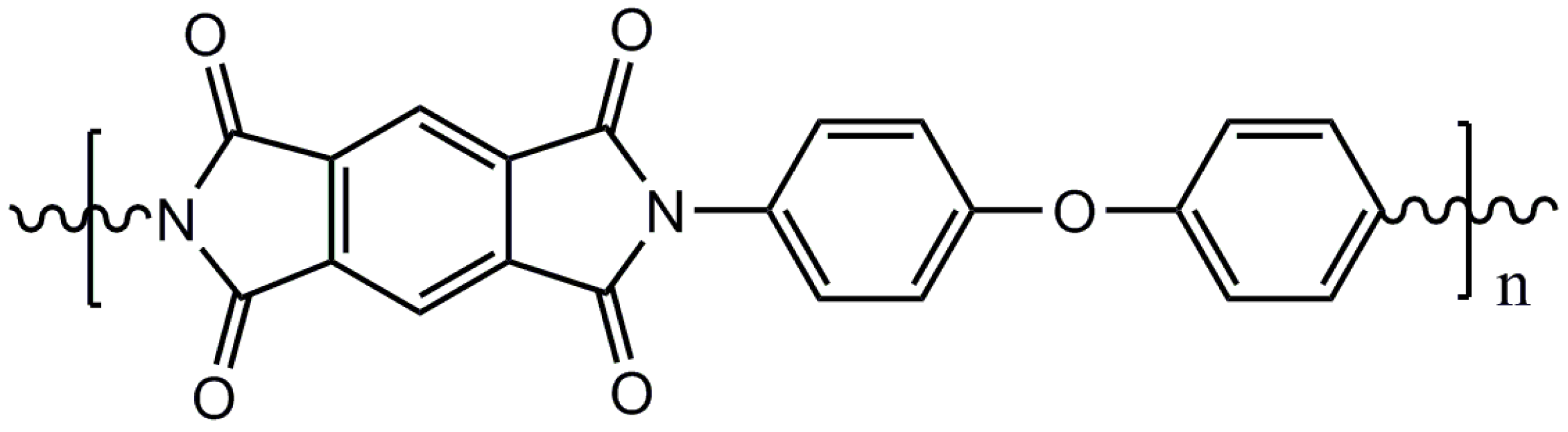
Design of Superlubricity System Using Si3N4/Polyimide as the Friction Pair and Nematic Liquid Crystals as the Lubricant
Abstract
:1. Introduction
2. Materials and Methods
2.1. Friction Test
2.1.1. Optimal Lubricant Screening
2.1.2. Friction Tests of the Optimal Lubricant
Point-Plane Contact
- (a)
- Different loads
- (b)
- Different rotation speeds
- (c)
- Long-time test
Plane–Plane Contact
2.2. Variation in Friction Part
2.2.1. Grinding of GCr15 Steel Plane or SiC Plane
GCr15 Steel Plane
SiC Plane
2.2.2. Plane-Plane Contact Friction Test of GCr15/PI or SiC/PI System
2.3. Surface Analysis of PI
2.3.1. Surface Topography Analysis
2.3.2. Surface-Enhanced Raman Scattering Spectra Analysis
3. Results and Discussion
3.1. Friction Test
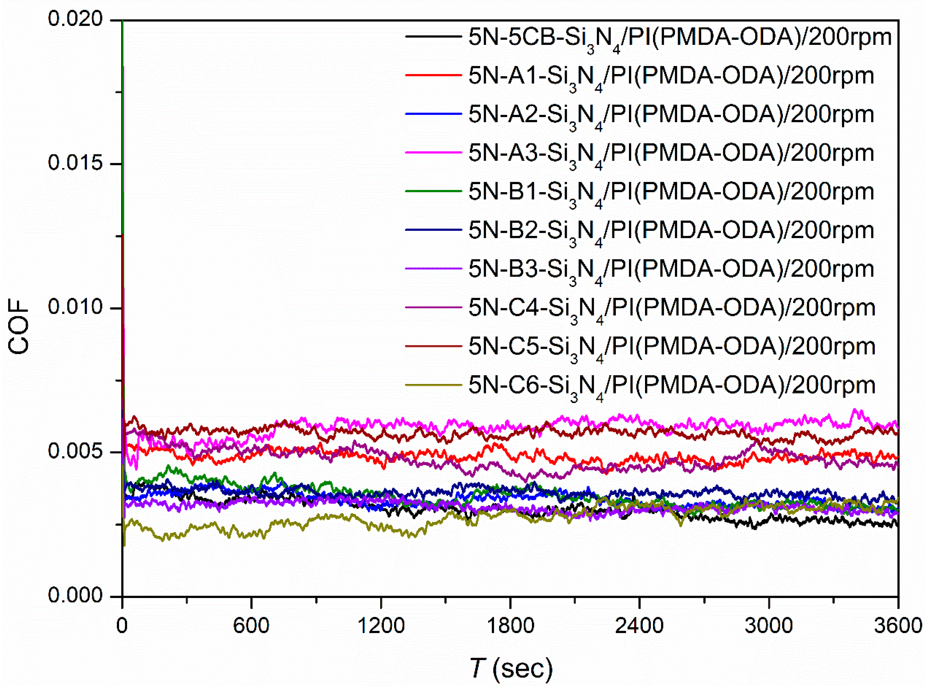
3.1.1. Optimal Lubricant Screening
3.1.2. Friction Tests with the Optimal Lubricant
Point–Plane Contact
- (a)
- Different loads
- (b)
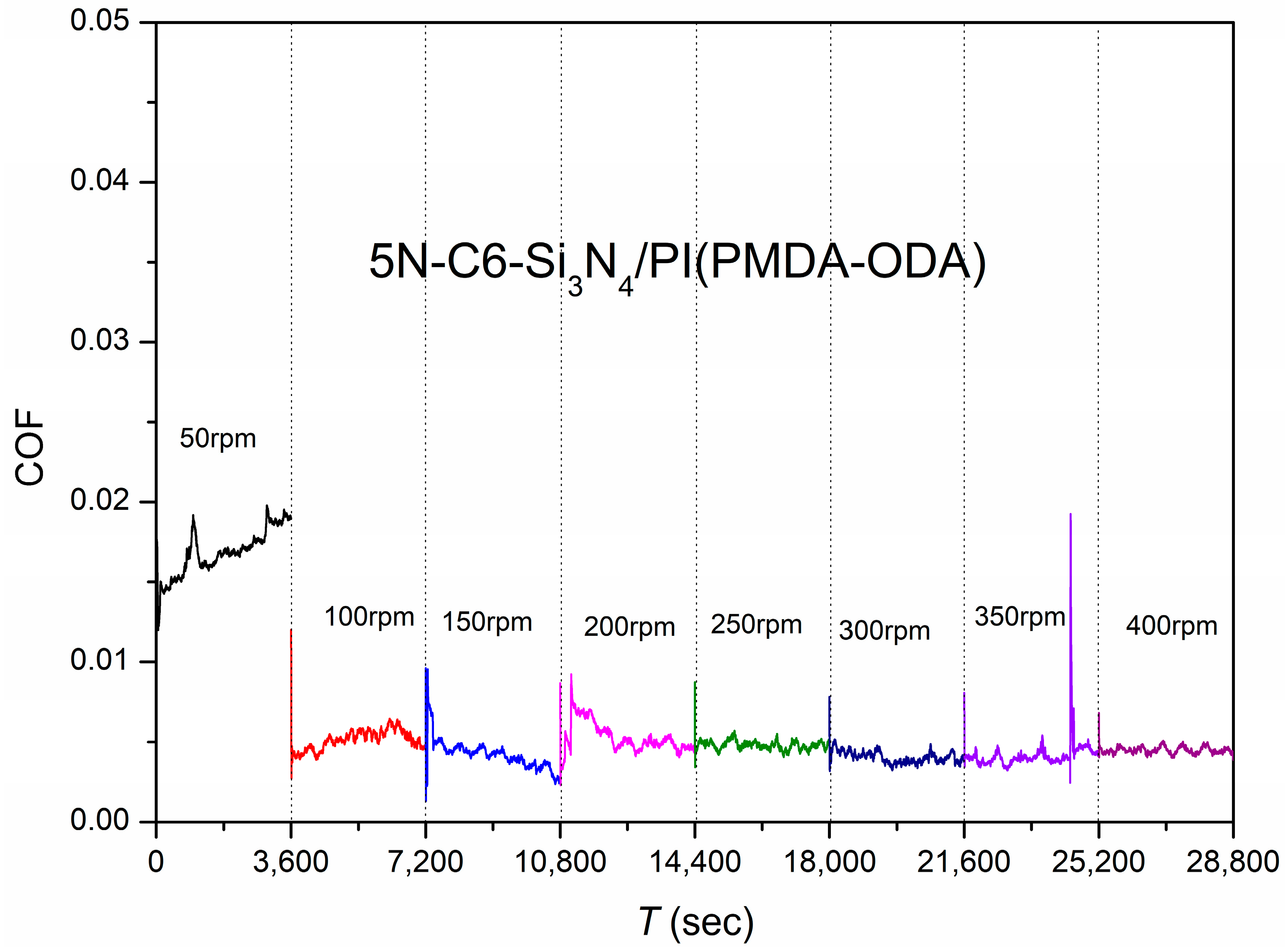
- Different speeds
- (c)
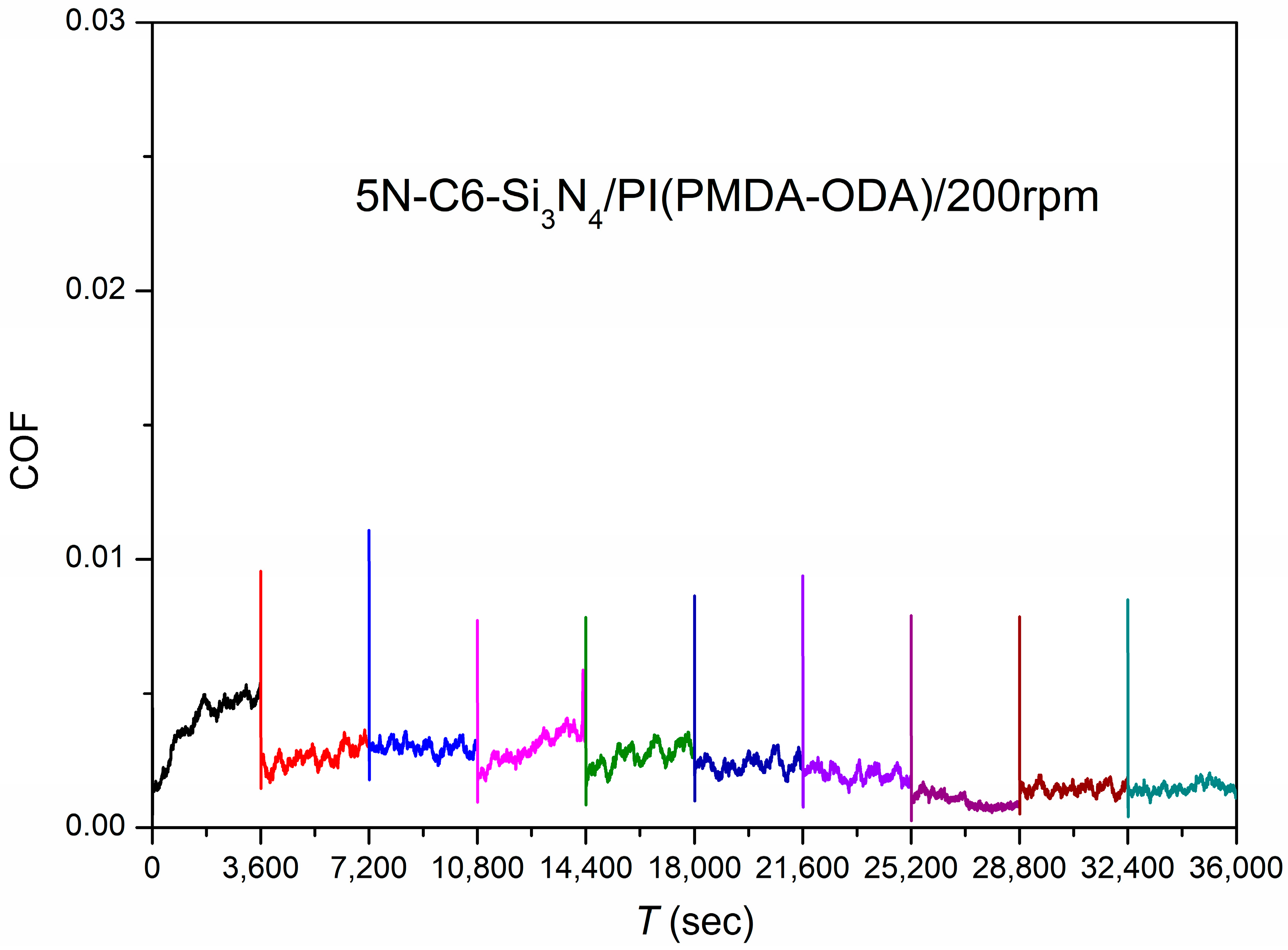
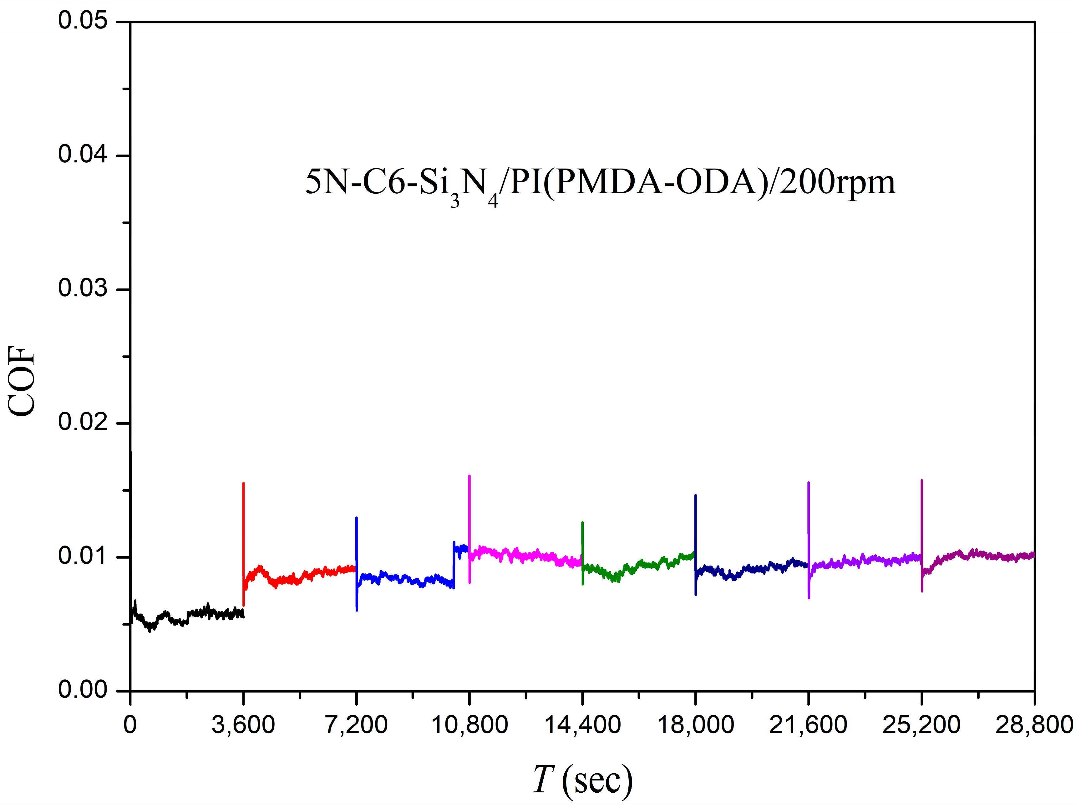
- Long-time test
Plane–Plane Contact
3.2. GCr15/PI or SiC/PI Friction System
3.2.1. GCr15/PI Friction System
3.2.2. SiC/PI Friction System
3.3. Surface Analysis of PI
3.3.1. Surface Topography Analysis
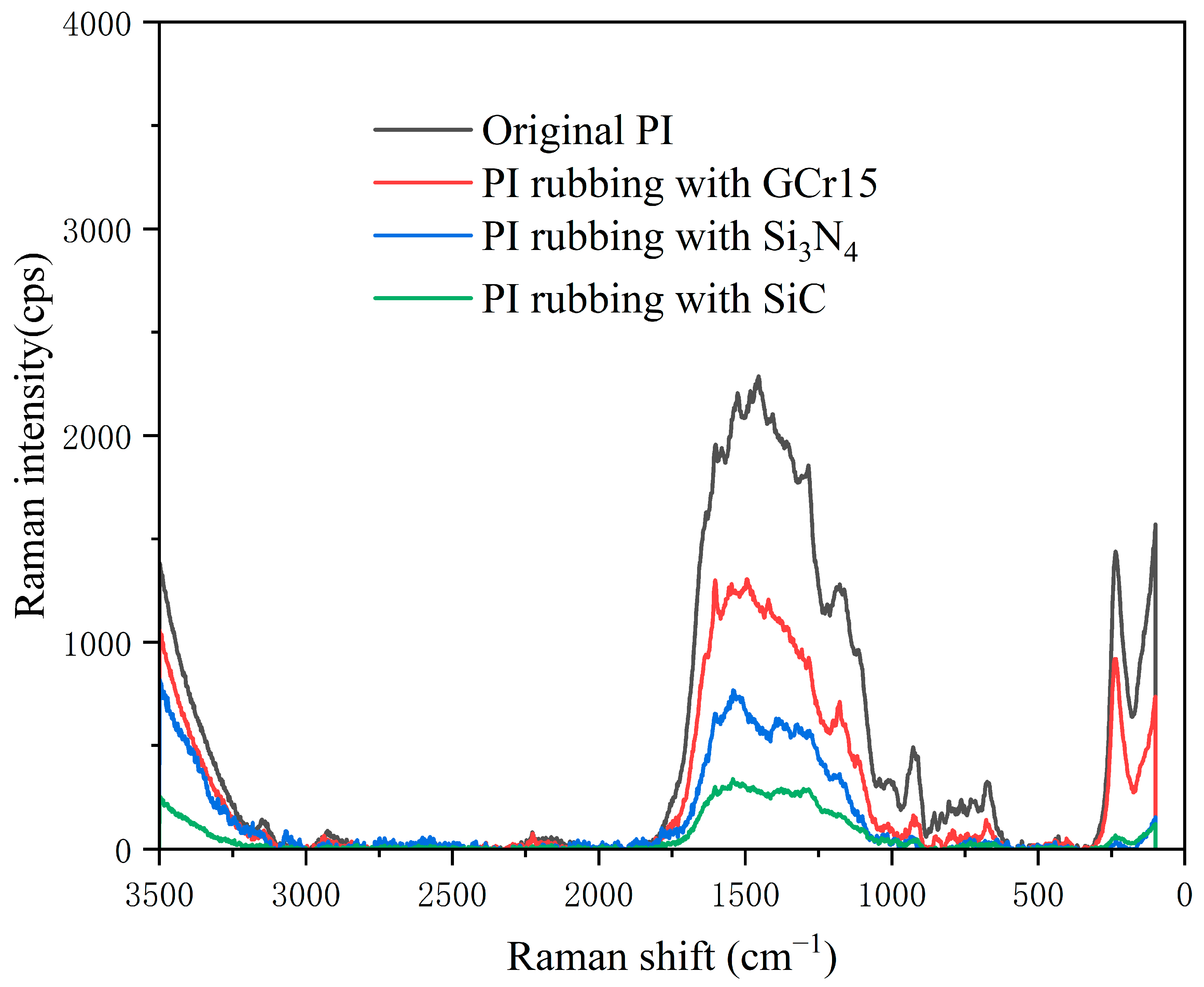
3.3.2. Surface Molecular Structure Analysis
4. Conclusions
Author Contributions
Funding
Institutional Review Board Statement
Data Availability Statement
Conflicts of Interest
References
- Kizilkaya, C.; Mülazim, Y.; Vezir Kahraman, M.; Kayaman Apohan, N.; Güngör, A. Synthesis and characterization of polyimide/hexagonal boron nitride composite. J. Appl. Polym. Sci. 2012, 124, 706–712. [Google Scholar] [CrossRef]
- Liu, Z.; Yang, J.; Grey, F.; Liu, J.Z.; Liu, Y.; Wang, Y.; Yang, Y.; Cheng, Y.; Zheng, Q. Observation of Microscale Superlubricity in Graphite. Phys. Rev. Lett. 2012, 108, 205503. [Google Scholar] [CrossRef] [PubMed]
- Yang, J.; Liu, Z.; Grey, F.; Xu, Z.; Li, X.; Liu, Y.; Urbakh, M.; Cheng, Y.; Zheng, Q. Observation of High-Speed Microscale Superlubricity in Graphite. Phys. Rev. Lett. 2013, 110, 255504. [Google Scholar] [CrossRef]
- Vu, C.C.; Zhang, S.; Urbakh, M.; Li, Q.; He, Q.C.; Zheng, Q. Observation of normal-force-independent superlubricity in mesoscopic graphite contacts. Phys. Rev. B 2016, 94, 081405. [Google Scholar] [CrossRef]
- Deng, H.; Ma, M.; Song, Y.; He, Q.; Zheng, Q. Structural superlubricity in graphite flakes assembled under ambient conditions. Nanoscale 2018, 10, 14314–14320. [Google Scholar] [CrossRef]
- Zhang, B.; Ji, L.; Lu, Z.; Li, H.; Zhang, J. Progress on Engineering Oriented Solid Superlubricity. Tribology 2023, 43, 3–17. [Google Scholar]
- Xiao, C.; Li, J.; Chen, L.; Zhang, C.; Zhou, N.; Qing, T.; Qian, L.; Zhang, J.; Luo, J. Water-based superlubricity in vacuum. Friction 2019, 7, 192–198. [Google Scholar] [CrossRef]
- Xu, J.; Kato, K. Formation of tribochemical layer of ceramics sliding in water and its role for low friction. Wear 2000, 245, 61–75. [Google Scholar] [CrossRef]
- Tomizawa, H.; Fischer, T.E. Friction and Wear of Silicon Nitride and Silicon Carbide in Water: Hydrodynamic Lubrication at Low Sliding Speed Obtained by Tribochemical Wear. ASLE Trans. 1987, 30, 41–46. [Google Scholar] [CrossRef]
- Gates, R.S.; Hsu, S.M. Tribochemistry Between Water and Si3N4 and SiC: Induction Time Analysis. Tribol. Lett. 2004, 17, 399–407. [Google Scholar] [CrossRef]
- Chen, Q.; Zhang, R.; He, Z.; Xiong, L. Effect of carbon-chain length and hydroxyl number on lubrication performance of alcohols. J. Hebei Univ. Sci. Technol. 2020, 42, 1–7. [Google Scholar]
- Wen, H.; Sun, J.; CHen, W. Review on Research Status and Development Trend on Silicon Nitride Ceramic Bearings. Mater Rev 2015, 29, 6–14. [Google Scholar]
- LI, J.; Luo, J. New technology for human getting rid of friction: Superlubricity. Chin. J. Nat. 2014, 36, 248–255. [Google Scholar]
- Liu, W.; Wang, H.; Liu, Y. Adjustable superlubricity system using polyalkylene glycol with various acid aqueous solutions. Friction 2023, 11, 1138–1149. [Google Scholar] [CrossRef]
- Ge, X.; Li, J.; Zhang, C.; Luo, J. Liquid Superlubricity of Polyethylene Glycol Aqueous Solution Achieved with Boric Acid Additive. Langmuir 2018, 34, 3578–3587. [Google Scholar] [CrossRef]
- Zhang, C.H.; Ma, Z.Z.; Luo, J.B.; Lu, X.C.; Wen, X.Z. Superlubricity of a Mixed Aqueous Solution. Chin. Phys. Lett. 2011, 28, 056201. [Google Scholar] [CrossRef]
- Li, J.; Zhang, C.; Luo, J. Superlubricity Behavior with Phosphoric Acid-Water Network Induced by Rubbing. Langmuir 2011, 27, 9413–9417. [Google Scholar] [CrossRef] [PubMed]
- Perez-Martinez, C.S.; Perkin, S. Interfacial Structure and Boundary Lubrication of a Dicationic Ionic Liquid. Langmuir 2019, 35, 15444–15450. [Google Scholar] [CrossRef]
- Smith, P.G. High-Temperature Molten-Salt Lubricated Hydrodynamic Journal Bearings. ASLE Trans. 1961, 4, 263–274. [Google Scholar] [CrossRef]
- Ge, X.; Li, J.; Zhang, C.; Wang, Z.; Luo, J. Superlubricity of 1-Ethyl-3-methylimidazolium trifluoromethanesulfonate Ionic Liquid Induced by Tribochemical Reactions. Langmuir 2018, 34, 5245–5252. [Google Scholar] [CrossRef]
- Zhang, Y.; Rutland, M.W.; Luo, J.; Atkin, R.; Li, H. Potential-Dependent Superlubricity of Ionic Liquids on a Graphite Surface. J. Phys. Chem. C 2021, 125, 3940–3947. [Google Scholar] [CrossRef]
- De Barros Bouchet, M.I.; Martin, J.M.; Avila, J.; Kano, M.; Yoshida, K.; Tsuruda, T.; Bai, S.; Higuchi, Y.; Ozawa, N.; Kubo, M.; et al. Diamond-like carbon coating under oleic acid lubrication: Evidence for graphene oxide formation in superlow friction. Sci. Rep. 2017, 7, 46394. [Google Scholar] [CrossRef] [PubMed]
- Li, J.; Zhang, C.; Deng, M.; Luo, J. Superlubricity of silicone oil achieved between two surfaces by running-in with acid solution. RSC Adv. 2015, 5, 30861–30868. [Google Scholar] [CrossRef]
- Li, K.; Zhang, S.; Liu, D.; Amann, T.; Zhang, C.; Yuan, C.; Luo, J. Superlubricity of 1,3-diketone based on autonomous viscosity control at various velocities. Tribol. Int. 2018, 126, 127–132. [Google Scholar] [CrossRef]
- Li, J.; Yuan, Y.; Amann, T.; Yuan, C.; Li, K. Macroscopic Oil-Based Superlubricity Achieved on Steel Surfaces with the Roughness of Engineering Level. Tribol. Lett. 2023, 71, 32. [Google Scholar] [CrossRef]
- Zeng, Q. Understanding the lubrication mechanism between the polyhydroxyl group lubricants and metal surfaces. J. Adhes Sci. Technol. 2018, 32, 1911–1924. [Google Scholar] [CrossRef]
- Zeng, Q.; Yu, F.; Dong, G. Superlubricity behaviors of Si3N4/DLC Films under PAO oil with nano boron nitride additive lubrication. Surf. Interface Anal. 2013, 45, 1283–1290. [Google Scholar] [CrossRef]
- Zeng, Q.; Dong, G.; Martin, J.M. Green superlubricity of Nitinol 60 alloy against steel in presence of castor oil. Sci. Rep. 2016, 6, 29992. [Google Scholar] [CrossRef]
- Ge, X.; Halmans, T.; Li, J.; Luo, J. Molecular behaviors in thin film lubrication—Part three: Superlubricity attained by polar and nonpolar molecules. Friction 2019, 7, 625–636. [Google Scholar] [CrossRef]
- Røn, T.; Javakhishvili, I.; Hvilsted, S.; Jankova, K.; Lee, S. Ultralow Friction with Hydrophilic Polymer Brushes in Water as Segregated from Silicone Matrix. Adv. Mater. Interfaces 2016, 3, 1500472. [Google Scholar] [CrossRef]
- Zhang, C.; Liu, Y.; Liu, Z.; Zhang, H.; Cheng, Q.; Yang, C. Regulation Mechanism of Salt Ions for Superlubricity of Hydrophilic Polymer Cross-Linked Networks on Ti6Al4V. Langmuir 2017, 33, 2133–2140. [Google Scholar] [CrossRef] [PubMed]
- Alghani, W.; Ab Karim, M.S.; Bagheri, S.; Amran, N.A.M.; Gulzar, M. Enhancing the Tribological Behavior of Lubricating Oil by Adding TiO2, Graphene, and TiO2/Graphene Nanoparticles. Tribol. Trans. 2019, 62, 452–463. [Google Scholar] [CrossRef]
- Ge, X.; Li, J.; Luo, R.; Zhang, C.; Luo, J. Macroscale Superlubricity Enabled by the Synergy Effect of Graphene-Oxide Nanoflakes and Ethanediol. ACS Appl. Mater. Interfaces 2018, 10, 40863–40870. [Google Scholar] [CrossRef] [PubMed]
- Yi, S.; Ge, X.; Li, J. Development and prospects of liquid superlubricity. J. Tsinghua Univ. Sci. Technol. 2020, 60, 617–629. [Google Scholar]
- Gao, X.; Chen, H.; Lv, S.; Zhang, Z.; Wang, T. Preliminary Study of the Superlubricity Behavior of Polyimide-Induced Liquid Crystal Alignment. J. Tribol. 2021, 144, 041901. [Google Scholar] [CrossRef]
- Gao, X.; Chen, H.; Yan, H.; Huang, C.; Wu, L.; Wang, T. Superlubricity by polyimide-induced alignment. Friction 2023, 11, 1690–1707. [Google Scholar] [CrossRef]
- Fang, Y.; Zhang, Q.; Wang, Y. Effects of Variety of Liquid Crystals and Process Conditions on Pretilt Angle. Polym. Eng. Sci. 2009, 25, 69–71. [Google Scholar]
- Cui, S. Research on the Start-Stop Wear and Thermal Slip Behavior of Heavy-Load and High-Speed Coated Hydrodynamic Journal Bearings; Harbin Institute of Technology: Harbin, China, 2022. [Google Scholar]
- Zhou, D.; Li, L.; Xue, G.; Ge, J.J.; Xue, C.; Cheng, S.Z.D. Molecular Orientation and Relaxation on a Surface of a Thin Film of Polymeric Liquid Crystalline. Langmuir 2002, 18, 4559–4561. [Google Scholar] [CrossRef]
- Moskovits, M. Surface selection rules. J. Chem. Phys. 1982, 77, 4408–4416. [Google Scholar] [CrossRef]
- Dong, W.; Paek, S.-H. Chemical structural effects of polyimides on the alignment and electro-optical properties of liquid crystal cells. Macromol. Res. 2004, 12, 251–257. [Google Scholar] [CrossRef]


| Abbreviation of LC Name | Molecular Formula |
|---|---|
| 5CB | 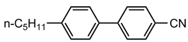 |
| 3UTPP2 | 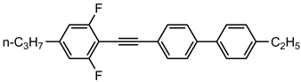 |
| 3UTPP4 | 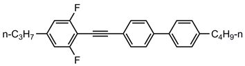 |
| 4UTPP3 | 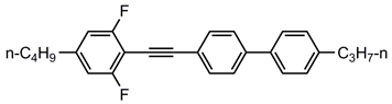 |
| 5CEPO2 | 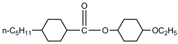 |
| 3CEPC3 |  |
| 2CEPPN |  |
| LC Name | Base Composition | Base Ratio (wt.%) | Minor Component | Minor Ratio (wt.%) |
|---|---|---|---|---|
| A1 | 5CB | 80 | 3UTPP2 | 20 |
| A2 | 5CB | 80 | 3UTPP4 | 20 |
| A3 | 5CB | 80 | 4UTPP3 | 20 |
| B1 | 5CB | 85 | 3UTPP2 | 15 |
| B2 | 5CB | 85 | 3UTPP4 | 15 |
| B3 | 5CB | 85 | 4UTPP3 | 15 |
| C4 | 5CB | 90 | 5CEPO2 | 10 |
| C5 | 5CB | 90 | 3CEPC3 | 10 |
| C6 | 5CB | 90 | 2CEPPN | 10 |
| Friction Pair | 2D Image | 3D Image |
|---|---|---|
| Si3N4/PI |  |  |
| GCr15/PI | 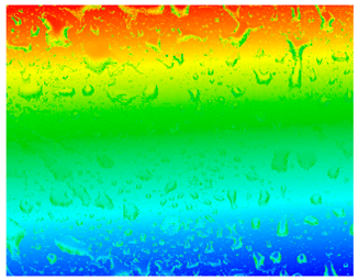 | 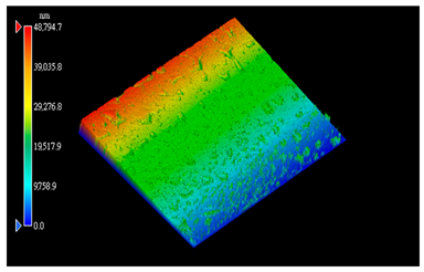 |
| SiC/PI | 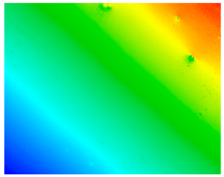 |  |
Disclaimer/Publisher’s Note: The statements, opinions and data contained in all publications are solely those of the individual author(s) and contributor(s) and not of MDPI and/or the editor(s). MDPI and/or the editor(s) disclaim responsibility for any injury to people or property resulting from any ideas, methods, instructions or products referred to in the content. |
© 2023 by the authors. Licensee MDPI, Basel, Switzerland. This article is an open access article distributed under the terms and conditions of the Creative Commons Attribution (CC BY) license (https://creativecommons.org/licenses/by/4.0/).
Share and Cite
Gao, X.; Cheng, Y.; Shi, M.; Chen, H.; Wu, L.; Wang, T. Design of Superlubricity System Using Si3N4/Polyimide as the Friction Pair and Nematic Liquid Crystals as the Lubricant. Polymers 2023, 15, 3693. https://doi.org/10.3390/polym15183693
Gao X, Cheng Y, Shi M, Chen H, Wu L, Wang T. Design of Superlubricity System Using Si3N4/Polyimide as the Friction Pair and Nematic Liquid Crystals as the Lubricant. Polymers. 2023; 15(18):3693. https://doi.org/10.3390/polym15183693
Chicago/Turabian StyleGao, Xinlei, Yuwei Cheng, Miaomiao Shi, Hao Chen, Li Wu, and Tingting Wang. 2023. "Design of Superlubricity System Using Si3N4/Polyimide as the Friction Pair and Nematic Liquid Crystals as the Lubricant" Polymers 15, no. 18: 3693. https://doi.org/10.3390/polym15183693