
Determination of Processing Precision of Hole in Industrial Plastic Materials


Abstract
:1. Introduction
- Finding the influence of the material on the precision of the processed hole;
- Finding the influence of the material on the diameter of the processed hole;
- Finding the influence of the cutting regime on the precision of the hole, with concrete reference to the deviation from cylindricity, i.e., the resulting diameter after processing.
2. Experimental Details
2.1. Material Type
- Material 1: POM-C (Polyacetal-Copolymer, EN ISO 1043);
- Material 2: PEHD 1000 (High Density Polyethylene);
- Material 3: PA6 (Polyamide, EN ISO 1874-1);
- Material 4: SIKA BLOCK M960 (Polyurethane-Hight Density);
- Material 5: SIKA BLOCK M980 (Polyurethane-Hight Density);
- Material 6: SIKA BLOCK M700 (Polyurethane-Medium Density).
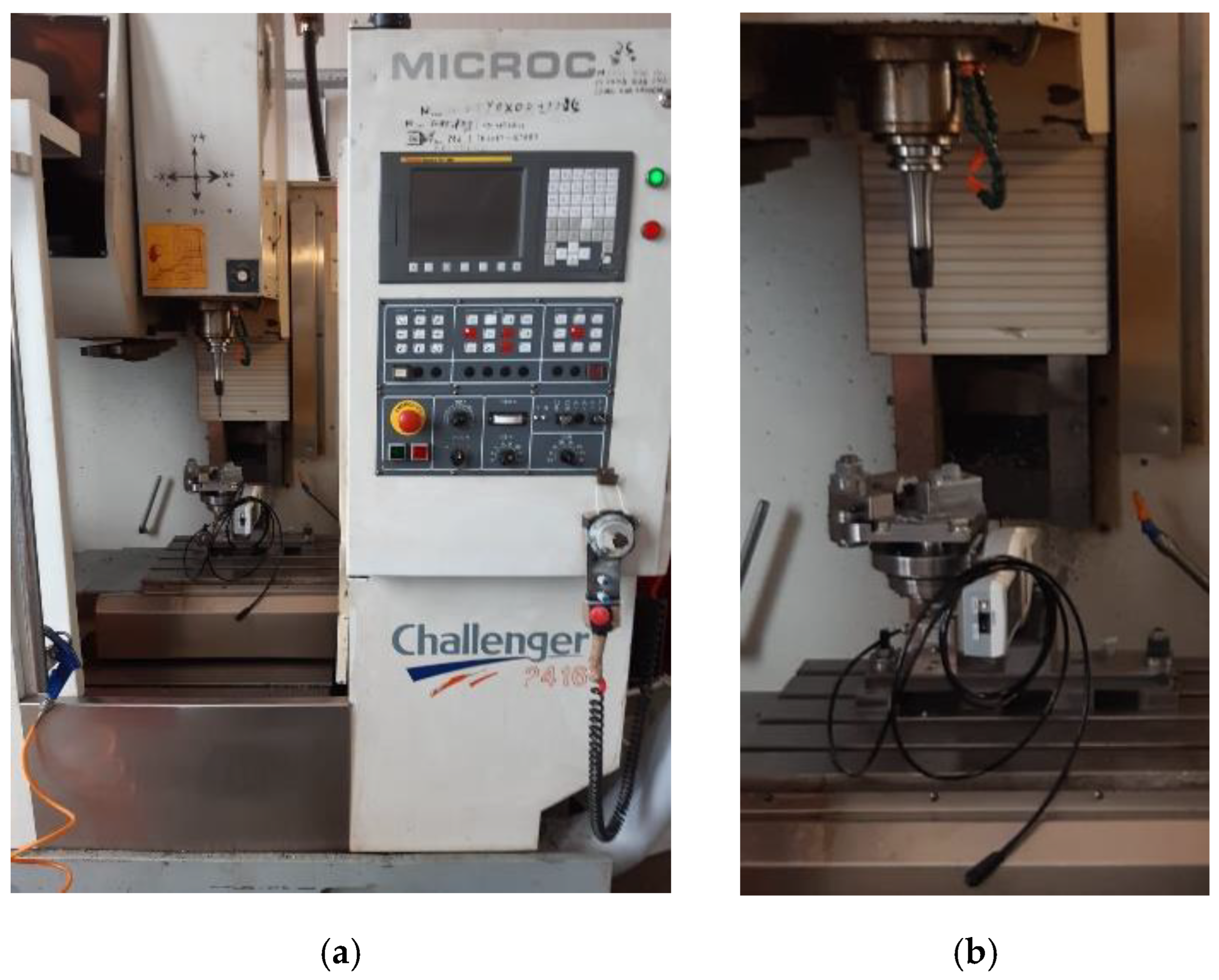
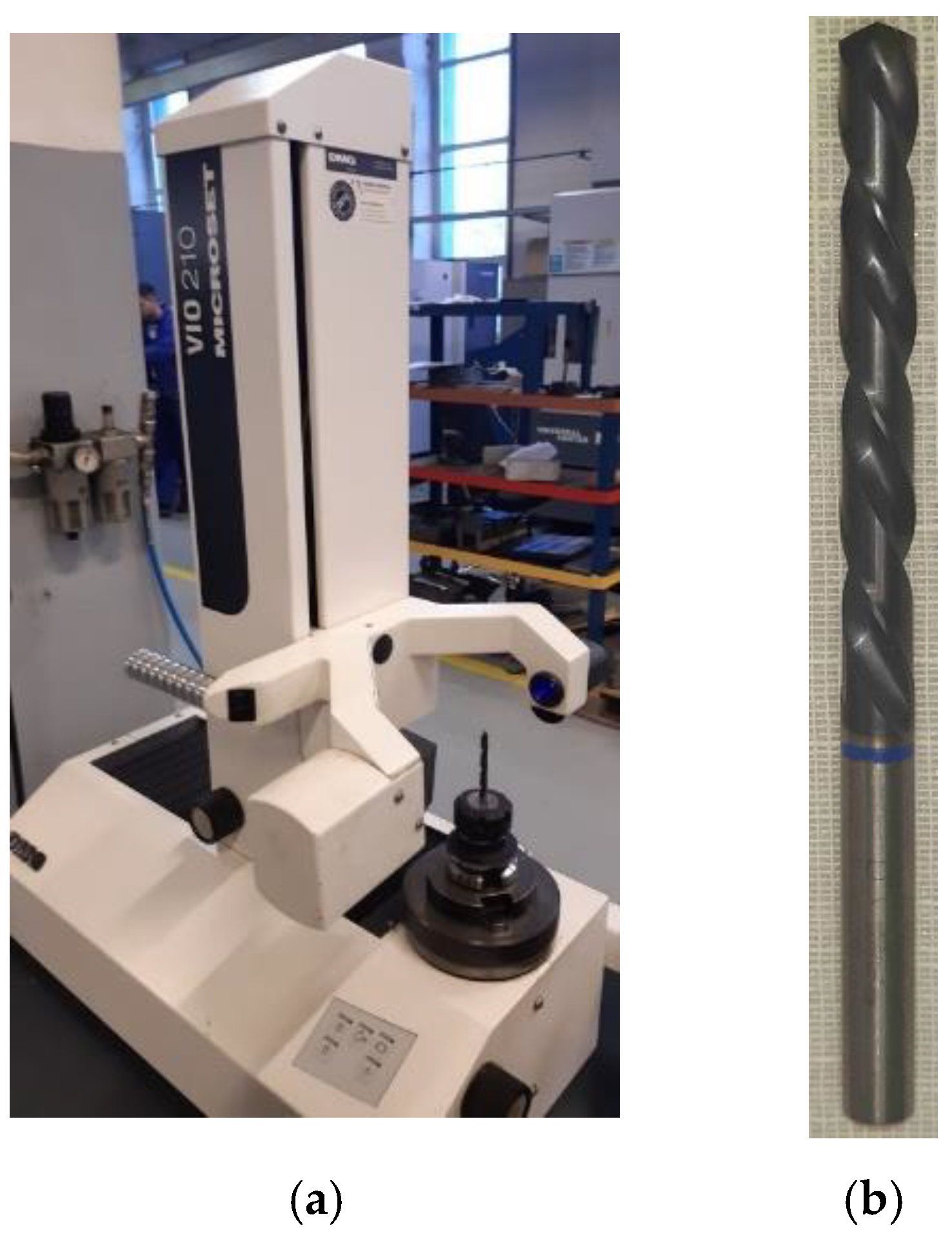
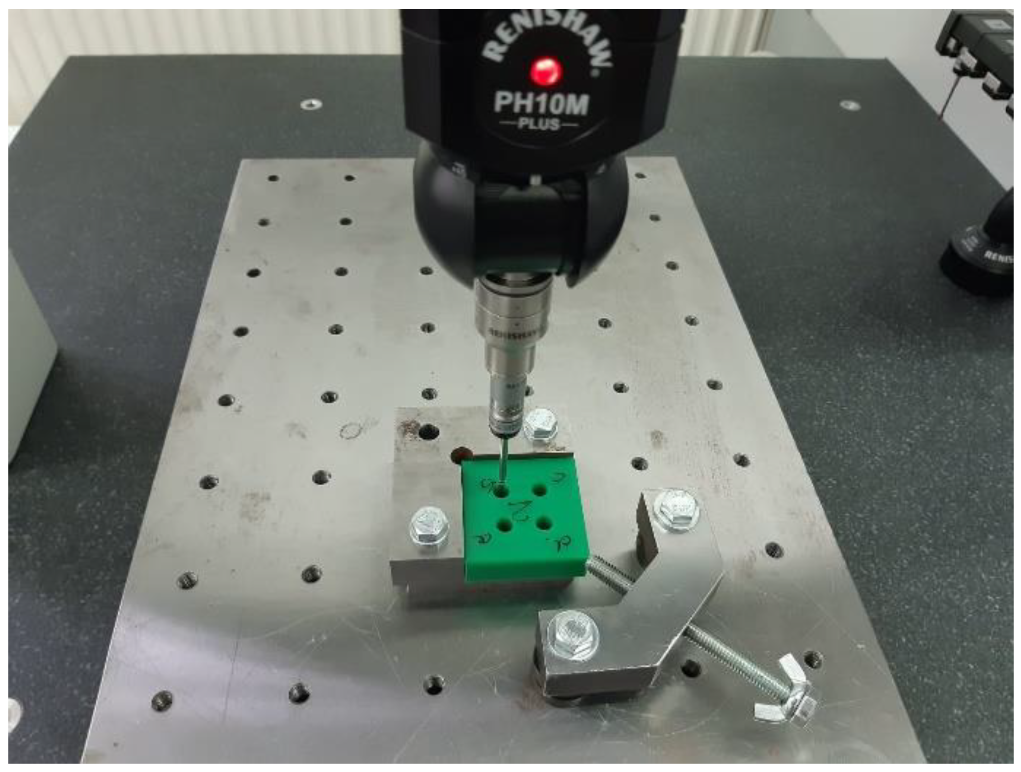
2.2. Processing of Holes in Test Pieces
- -
- Volumetric accuracy: 1.8 µm + L/400 (L is the measured length).
- -
- Repeatability: 1.7 µm.
- -
- Velocity: 762 mm/s.
- -
- Acceleration: 2.306 mm/s2.
- Cutting speed—3 levels: 12, 25, 37 [m/min].
- Feed—4 levels: 0.1; 0.2; 0.3; 0.4 [mm/rpm].
3. Conduct and Analyze Our Experimental Design
- Principle of randomness, based on which statistical methods require that the observations (or errors) have a random character, that is, they are randomly distributed (randomized) with respect to the parameters. Randomization of observations makes this assumption valid.
- The principle of replication, which involves repeating the experiment 3 to 7 times for each set of values of the input parameters. This procedure is necessary to decide the constancy of the measurements.
- The principle of working in “blocks”, which is used to improve the precision of the comparison between the factors used.
4. Determination of the Influence of the Material on the Precision of the Machined Hole
5. Determination of the Influence of the Material on the Diameter of the Hole Machined

| Cutting Parameter No. | 1 | 2 | 3 | 4 | 5 | 6 | 7 | 8 | 9 | 10 | 11 | 12 | (Figure 10) | ||
|---|---|---|---|---|---|---|---|---|---|---|---|---|---|---|---|
| v [m/min] | 12 | 25 | 37 | 12 | 25 | 37 | 12 | 25 | 37 | 12 | 25 | 37 | Hole diameter | Δ diameter | |
| s [mm/tooth] | 0.05 | 0.05 | 0.05 | 0.1 | 0.1 | 0.1 | 0.15 | 0.15 | 0.15 | 0.2 | 0.2 | 0.2 | |||
| f [mm/rev] | 0.1 | 0.1 | 0.1 | 0.2 | 0.2 | 0.2 | 0.3 | 0.3 | 0.3 | 0.4 | 0.4 | 0.4 | |||
| Hole diameter depending on regime | min | max | |||||||||||||
| PomC | 6.641 | 6.695 | 6.712 | 6.662 | 6.671 | 6.671 | 6.664 | 6.665 | 6.653 | 6.731 | 6.746 | 6.721 | 6.641 | 6.746 | 0.105 |
| PEHD 1000 | 6.505 | 6.55 | 6.584 | 6.565 | 6.562 | 6.568 | 6.601 | 6.613 | 6.607 | 6.566 | 6.615 | 6.644 | 6.505 | 6.644 | 0.139 |
| PA6 | 6.604 | 6.64 | 6.654 | 6.632 | 6.609 | 6.631 | 6.633 | 6.629 | 6.62 | 6.667 | 6.675 | 6.661 | 6.604 | 6.675 | 0.071 |
| M960 | 6.712 | 6.717 | 6.707 | 6.676 | 6.686 | 6.693 | 6.675 | 6.675 | 6.681 | 6.724 | 6.726 | 6.729 | 6.675 | 6.729 | 0.054 |
| M980 | 6.697 | 6.709 | 6.697 | 6.693 | 6.694 | 6.702 | 6.705 | 6.693 | 6.701 | 6.644 | 6.697 | 6.688 | 6.644 | 6.709 | 0.065 |
| M700 | 6.694 | 6.705 | 6.689 | 6.685 | 6.682 | 6.673 | 6.685 | 6.685 | 6.683 | 6.697 | 6.691 | 6.698 | 6.673 | 6.705 | 0.032 |
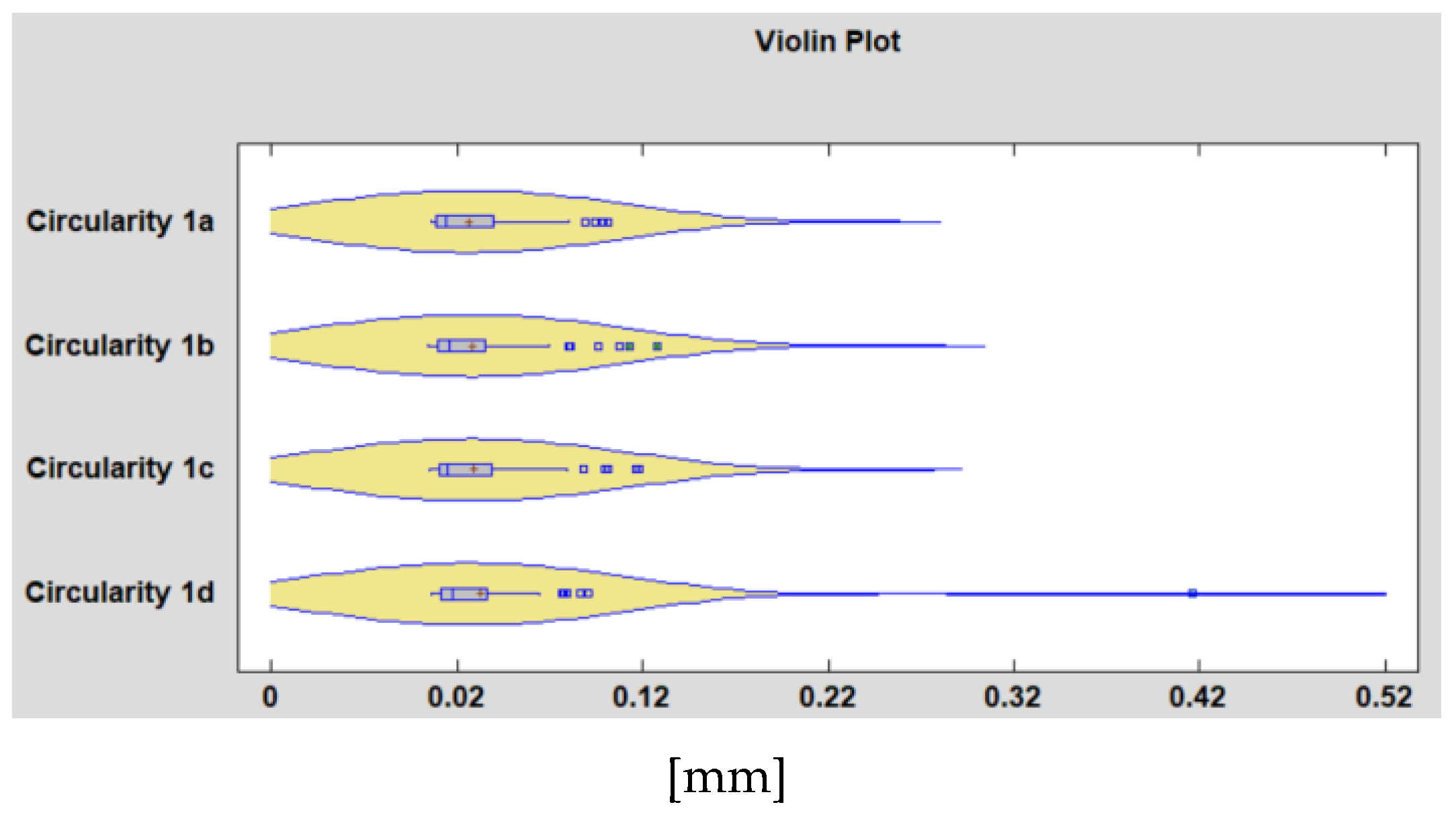
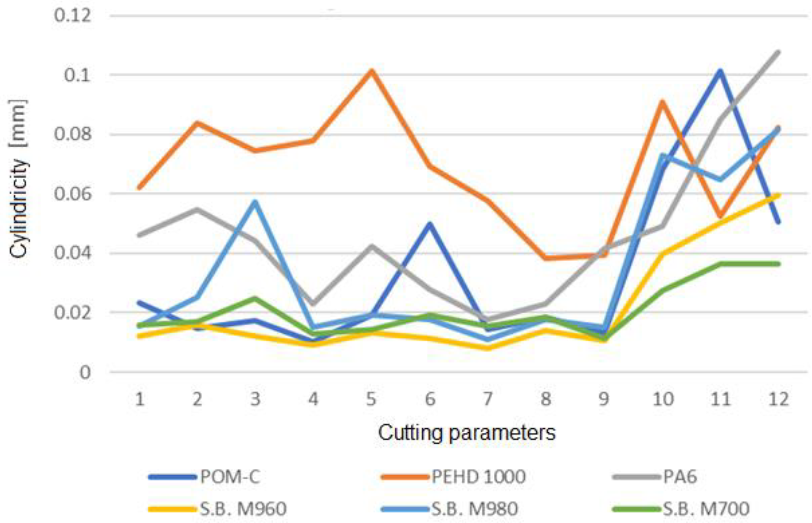
6. Determination of the Influence of the Chipping Regime on the Precision of the Hole—With Specific Reference to the Deviation from Cylindricality, or the Resulting Diameter after Processing
7. Discussions
8. Conclusions
- +0.1 mm in the case of POM-C material
- +0.1 mm in the case of SikaBlock M700, M960 materials
- +0.2 mm in the case of PA6 material
- +0.2 mm in the case of SikaBlock M980 material
- +0.3 mm in the case of PEHD 1000 material
- Analyzing the experimental data through the prism of evaluating the random nature of the data and eliminating outliers from the samples.
- Expanding the research also on the hole diameters specific to M5, M6, M10, M12, M14 threads, threads often encountered in the parts manufactured from the studied materials.
- Identification of the influence of the hole diameter on the precision and quality of the processed thread.
Author Contributions
Funding
Institutional Review Board Statement
Informed Consent Statement
Data Availability Statement
Conflicts of Interest
References
- Wang, F.-J.; Zhao, M.; Yan, J.-B.; Qiu, S.; Liu, X.; Zhang, B.-Y. Investigation of Damage Reduction When Dry-Drilling Aramid Fiber-Reinforced Plastics Based on a Three-Point Step Drill. Materials 2020, 13, 5457. [Google Scholar] [CrossRef] [PubMed]
- Liu, S.; Yang, T.; Liu, C.; Du, Y. Comprehensive investigation of cutting mechanisms and hole quality in dry drilling woven aramid fibre–reinforced plastic with typical tools. Proc. Inst. Mech. Eng. Part B J. Eng. Manuf. 2019, 233, 2471–2491. [Google Scholar] [CrossRef]
- Masoud, F.; Sapuan, S.; Ariffin, M.M.; Nukman, Y.; Bayraktar, E. Cutting Processes of Natural Fiber-Reinforced Polymer Composites. Polymers 2020, 12, 1332. [Google Scholar] [CrossRef]
- Çelik, Y.H.; Kilickap, E.; Kilickap, A.İ. An experimental study on milling of natural fiber (jute)-reinforced polymer composites. J. Compos. Mater. 2019, 53, 3127–3137. [Google Scholar] [CrossRef]
- Maleki, H.R.; Hamedi, M.; Kubouchi, M.; Arao, Y. Experimental study on drilling of jute fiber reinforced polymer composites. J. Compos. Mater. 2019, 53, 283–295. [Google Scholar] [CrossRef]
- Polini, W.; Corrado, A. A general model to estimate hole location deviation in drilling: The contribution of three error sources. Int. J. Adv. Manuf. Technol. 2019, 102, 545–557. [Google Scholar] [CrossRef]
- Shen, N.; Guo, Z.; Li, J.; Tong, L.; Zhu, K. A practical method of improving hole position accuracy in the robotic drilling process. Int. J. Adv. Manuf. Technol. 2018, 96, 2973–2978. [Google Scholar] [CrossRef]
- Los, A.; Mayer, J.R.R. Application of the adaptive Monte Carlo method in a five-axis machine tool calibration uncertainty estimation including the thermal behaviour. Precis. Eng. 2018, 53, 17–25. [Google Scholar] [CrossRef]
- Gameros, A.; Lowth, S.; Axinte, D.; Nagy-Sochacki, A.; Craing, O.; Siller, H.R. State-of-the-art in fixture systems for the manufacture and assembly of rigid components: A review. Int. J. Mach. Tools Manuf. 2017, 123, 1–21. [Google Scholar] [CrossRef]
- Abdullah, A.B.; Sapuan, S.M. Hole-Making and Drilling Technology for Composites, 1st ed.; Woodhead: Duxford, UK, 2019; pp. 1–100. [Google Scholar]
- Altan, M.; Altan, E. Investigation of burr formation and surface roughness in drilling engineering plastics. J. Braz. Soc. Mech. Sci. Eng. 2014, 36, 347–354. [Google Scholar] [CrossRef]
- Ravai, N.S.; Lobontiu, M.; Medan, N.; Szigeti, F. Experimental studies on drilling in cryogenic conditions the industrial plastic parts. Matec Web Conf. 2017, 112, 01024. [Google Scholar] [CrossRef] [Green Version]
- Varga, G.; Ravai-Nagy, S.; Szigeti, F. Examination of Surface Roughness of Holes of Plastic Parts Drilled Under Cryogenic Cooling Conditions. IOP Conf. Ser. Mater. Sci. Eng. 2018, 448, 012065. [Google Scholar] [CrossRef]
- Dhakal, H.N.; Ismail, S.O.; Ojo, S.O.; Paggi, M.; Smith, J.R. Abrasive water jet drilling of advanced sustainable bio-fibre-reinforced polymer/hybrid composites: A comprehensive analysis of machining-induced damage responses. Int. J. Adv. Manuf. Technol. 2018, 99, 2833–2847. [Google Scholar] [CrossRef] [Green Version]
- KC, B.; Faruk, O.; Agnelli, J.A.M.; Leao, A.L.; Tjong, J.; Sain, M. Sisal-glass fiber hybrid biocomposite: Optimization of injection molding parameters using Taguchi method for reducing shrinkage. Compos. Part A Appl. Sci. Manuf. 2016, 83, 152–159. [Google Scholar] [CrossRef] [Green Version]
- Almansour, F.A.; Dhakal, H.N.; Zhang, Z.Y. Effect of water absorption on Mode I interlaminar fracture toughness of flax/basalt reinforced vinyl ester hybrid composites. Compos. Struct. 2017, 168, 813–825. [Google Scholar] [CrossRef] [Green Version]
- Heidarya, H.; Karimib, N.Z.; Minak, G. Investigation on delamination and flexural properties in drilling of carbon nanotube/polymer composites. Compos. Struct. 2018, 201, 112–120. [Google Scholar] [CrossRef]
- Díaz-Álvarez, A.; Rubio-López, Á.; Santiuste, C.; Miguélez, M.H. Experimental analysis of drilling induced damage in biocomposites. Text. Res. J. 2018, 88, 2544–2558. [Google Scholar] [CrossRef]
- Ciecieląg, K. Study on the Machinability of Glass, Carbon and Aramid Fiber Reinforced Plastics in Drilling and Secondary Drilling Operations. Adv. Sci. Technol. Res. J. 2022, 16, 57–66. [Google Scholar] [CrossRef]
- Singh, Y.; Singh, J.; Sharma, S.; Sharma, A.; Chohan, J. Process parameter optimization in laser cutting of Coir fiber reinforced Epoxy composite-a review. Mater. Today Proc. 2021, 48, 1021–1027. [Google Scholar] [CrossRef]
- Khashaba, U.A.; Abd-Elwahed, M.S.; Eltaher, M.A.; Najjar, I.; Melaibari, A.; Ahmed, K.I. Thermo-Mechanical and Delamination Properties in Drilling GFRP Composites by Various Drill Angles. Polymers 2021, 13, 1884. [Google Scholar] [CrossRef]
- Hoekstra, B.; Shekarian, A.; Kolasangiani, K.; Oguamanam, D.C.; Zitoune, R.; Bougherara, H. Effect of machining processes on the damage response and surface quality of open hole hybrid carbon/flax composites: An experimental study. Compos. Struct. 2022, 285, 115244. [Google Scholar] [CrossRef]
- Babu, J.; Madarapu, A.; Sunny, T.; Ramana, M.V. Multi characteristic optimization of high-speed machining of GFRP laminate by hybrid Taguchi desirability approach. Mater. Today Proc. 2022, 58, 238–243. [Google Scholar] [CrossRef]
- Montgomery, D.C. Design and Analysis of Experiments; John Wiley & Sons: Hoboken, NJ, USA, 2017. [Google Scholar]


| POM-C | PEHD 1000 | PA6 | SIKA BLOCK | |||
|---|---|---|---|---|---|---|
| M960 | M980 | M700 | ||||
| Density [g/cm3] | 1.41 | 0.93 | 1.14 | 1.2 | 1.35 | 0.7 |
| Shore hardness [scale D] | 81 | 51 | 83 | 78 | 86 | 66 |
| Flexural strength [MPa] | 91 | 27 | 130 | 80 | 145 | 26 |
| E-Modulus [MPa] | 2800 | 750 | 3300 | 2200 | 4000 | 1000 |
| Compressive strength [MPa] | 68 | 65 | 68 | 70 | 120 | 25 |
| Impact resistance [kJ/m2] | 6 | No Break | 3 | 30 | 35 | 7 |
| Heat distortion temperature [°C] | 110 | 135 | 220 | 80 | 85 | 90 |
| Linear thermal expansion coefficient αT [K−1] | 110 × 10−6 | 200 × 10−6 | 100 × 10−6 | 85 × 10−6 | 60 × 10−6 | 55 × 10−6 |
| Tensile strength [MPa] | 67 | 17 | 85 | No data | No data | No data |
| Unit | Value | |
|---|---|---|
| Spindle speed | [rpm] | 10,000 |
| Spindle Power (continue/peak) | [kW] | 5.5/7.5 |
| Feed rates, maximum cutting axis x/y/z | [m/min] | 10/10/10 |
| Positioning accuracy | [mm] | +/−0.005 |
| Repeatability | [mm] | +/−0.004 |
| Material | Cutting Speed [m/min] | Feed [mm/rev] | Circularity [mm] | Average Sample Circularity [mm] | Hole |
|---|---|---|---|---|---|
| 3 | 37 | 0.4 | 0.416 | 0.027 | 1d |
| 1 | 37 | 0.3 | 0.472 | 0.025 | 2c |
| 2 | 37 | 0.2 | 0.103 | 2c | |
| 2 | 12 | 0.1 | 0.103 | 2c |
| Measurement Plan 1 | Measurement Plan 2 | |||
|---|---|---|---|---|
| Model | Correlation | R-Squared | Correlation | R-Squared |
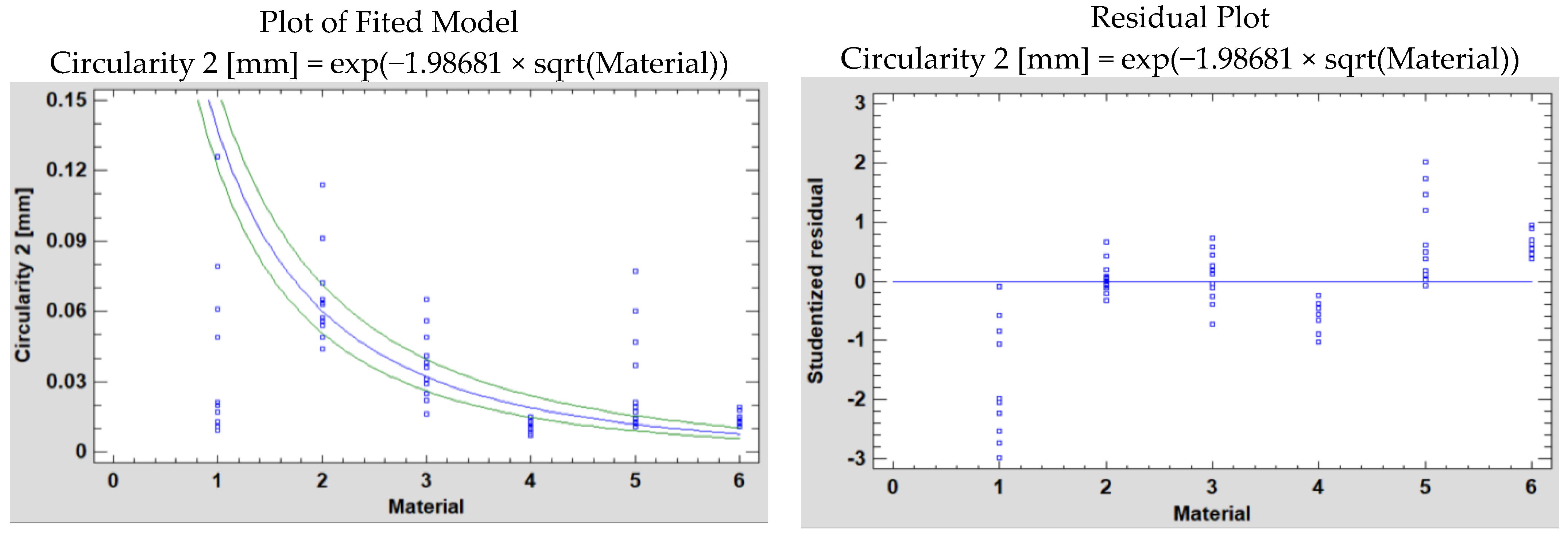
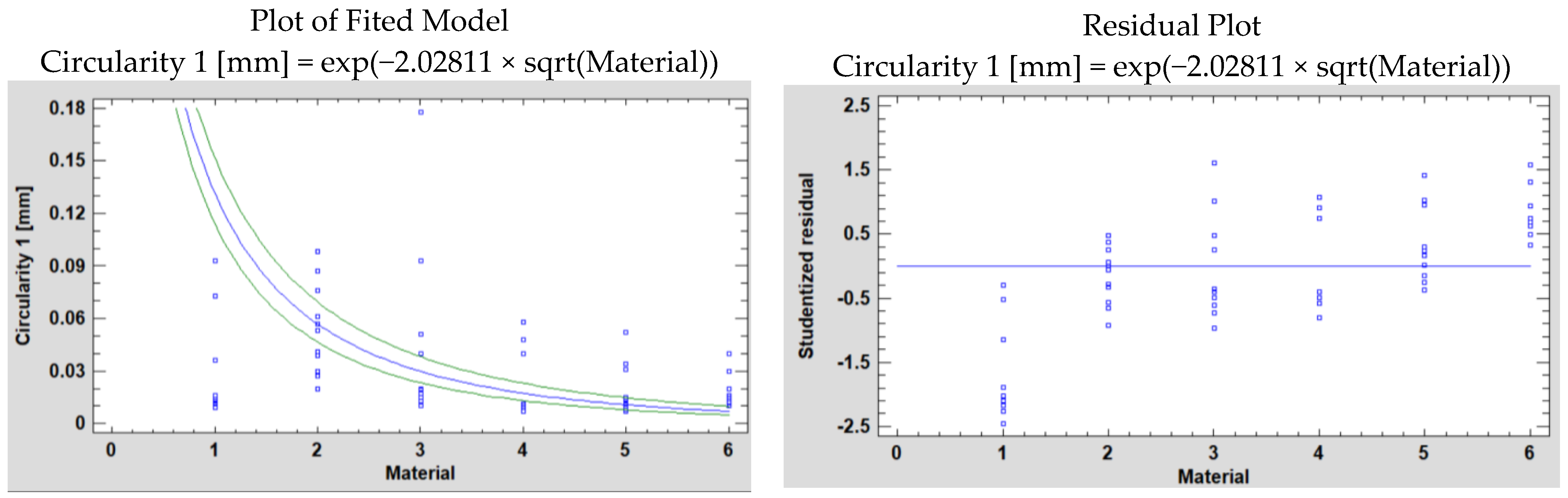
| Logarithmic-Y square root-X | −0.9588 | 91.93% | −0.9684 | 93.78% |
| Log probit | −0.9058 | 82.05% | −0.9201 | 84.66% |
| Exponential | −0.9042 | 81.76% | −0.9209 | 84.80% |
| Squared-Y | 0.2636 | 6.95% | 0.3134 | 9.82% |
| Double squared | 0.1723 | 2.97% | 0.1943 | 3.78% |
| Least Squares | Standard | T | ||
|---|---|---|---|---|
| Parameter | Estimate | Error | Statistic | p-Value |
| Slope P1 | −2.02811 | 0.071295 | −28.4468 | 0.0000 |
| Slope P2 | −1.98681 | 0.060744 | −32.708 | 0.0000 |
| Source | Measuring Plane | Sum of Squares | Df | Mean Square | F-Ratio | p-Value |
|---|---|---|---|---|---|---|
| Model | P1 | 1036.53 | 1 | 1036.53 | 809.22 | 0.0000 |
| P2 | 994.753 | 994.753 | 1069.81 | |||
| Residual | P1 | 90.9446 | 71 | 1.28091 | ||
| P2 | 66.0185 | 0.929838 | ||||
| Total | P1 | 1127.48 | 72 | |||
| P2 | 1060.77 |
| Material | Diameter [mm] | Compared to 6.824 [mm] | To Obtain the 6.8 mm Hole, Choose a Tool with a Larger Diameter | Drill Diameter to Be Fixed in the Tool Holder [mm] | Diameter Measured Drill along with Tool Holder [mm] | ||||
|---|---|---|---|---|---|---|---|---|---|
| Min | Max | Min | Max | Average | |||||
| 1. | POM-C | 6.641 | 6.746 | 0.183 | 0.078 | 0.1305 | +0.1 mm | 6.7 + 0.1 = 6.8 mm | 6.824 + 0.1 = 6.92 mm |
| 2. | PEHD 1000 | 6.505 | 6.644 | 0.319 | 0.18 | 0.2495 | +0.3 mm | 6.7 + 0.3 = 7.0 mm | 6.824 + 0.3 = 7.12 mm |
| 3. | PA6 | 6.604 | 6.675 | 0.22 | 0.149 | 0.1845 | +0.2 mm | 6.7 + 0.2 = 6.9 mm | 6.824 + 0.2 = 7.02 mm |
| 4. | M960 | 6.675 | 6.729 | 0.149 | 0.095 | 0.122 | +0.1 mm | 6.7 + 0.1 = 6.8 mm | 6.824 + 0.1 = 6.92 mm |
| 5. | M980 | 6.644 | 6.709 | 0.18 | 0.115 | 0.1475 | +0.2 mm | 6.7 + 0.2 = 6.9 mm | 6.824 + 0.2 = 7.02 mm |
| 6. | M700 | 6.673 | 6.705 | 0.151 | 0.119 | 0.135 | +0.1 mm | 6.7 + 0.1 = 6.8 mm | 6.824 + 0.1 = 6.92 mm |
| No. | Material | Minimum Diameter [mm] | Maximum Diameter [mm] | Tolerance [mm] | Class |
|---|---|---|---|---|---|
| POM-C | 6.641 | 6.746 | 0.105 | IT12 | |
| PEHD 1000 | 6.505 | 6.644 | 0.139 | IT13 | |
| PA6 | 6.604 | 6.675 | 0.071 | IT11 | |
| M960 | 6.675 | 6.729 | 0.054 | IT11 | |
| M980 | 6.644 | 6.709 | 0.065 | IT11 | |
| M700 | 6.673 | 6.705 | 0.032 | IT10 |
| No. | Material | Minimum Diameter [mm] | Maximum Diameter [mm] | Tolerance [mm] | Class |
|---|---|---|---|---|---|
| POM-C | 6.641 | 6.712 | 0.071 | IT11 | |
| PEHD 1000 | 6.505 | 6.613 | 0.108 | IT12 | |
| PA6 | 6.604 | 6.654 | 0.05 | IT10 | |
| M960 | 6.675 | 6.717 | 0.042 | IT10 | |
| M980 | 6.693 | 6.709 | 0.016 | IT8 | |
| M700 | 6.673 | 6.705 | 0.032 | IT9 |
| Hole Tolerance Depending on Cutting Parameters | ||||||||||||
|---|---|---|---|---|---|---|---|---|---|---|---|---|
| No. cutting regime | 1 | 2 | 3 | 4 | 5 | 6 | 7 | 8 | 9 | 10 | 11 | 12 |
| v [m/min] | 12 | 25 | 37 | 12 | 25 | 37 | 12 | 25 | 37 | 12 | 25 | 37 |
| s [mm/tooth] | 0.05 | 0.05 | 0.05 | 0.1 | 0.1 | 0.1 | 0.15 | 0.15 | 0.15 | 0.2 | 0.2 | 0.2 |
| f [mm/rev] | 0.1 | 0.1 | 0.1 | 0.2 | 0.2 | 0.2 | 0.3 | 0.3 | 0.3 | 0.4 | 0.4 | 0.4 |
| POM-C Average of measured cylindricity | 0.0235 | 0.0149 | 0.0175 | 0.0104 | 0.0193 | 0.05 | 0.0142 | 0.0183 | 0.0133 | 0.0683 | 0.1013 | 0.0505 |
| Min [mm] | 0.019 | 0.009 | 0.01 | 0.007 | 0.012 | 0.013 | 0.007 | 0.011 | 0.007 | 0.055 | 0.089 | 0.038 |
| Max [mm] | 0.033 | 0.023 | 0.026 | 0.014 | 0.031 | 0.15 | 0.046 | 0.029 | 0.026 | 0.077 | 0.141 | 0.072 |
| 0.014 | 0.014 | 0.016 | 0.007 | 0.019 | 0.137 | 0.039 | 0.018 | 0.019 | 0.022 | 0.052 | 0.034 | |
| IT | 7 | 7 | 8 | 6 | 8 | 12 | 10 | 8 | 8 | 8 | 10 | 9 |
| PEHD 1000Average of measured cylindricity | 0.0623 | 0.084 | 0.0745 | 0.0779 | 0.1015 | 0.0691 | 0.0578 | 0.0384 | 0.0395 | 0.091 | 0.0525 | 0.0823 |
| Min [mm | 0.043 | 0.057 | 0.04 | 0.03 | 0.053 | 0.035 | 0.031 | 0.025 | 0.024 | 0.055 | 0.023 | 0.048 |
| Max [mm] | 0.095 | 0.112 | 0.128 | 0.185 | 0.24 | 0.134 | 0.173 | 0.078 | 0.057 | 0.125 | 0.092 | 0.115 |
| 0.052 | 0.055 | 0.088 | 0.155 | 0.187 | 0.099 | 0.142 | 0.053 | 0.033 | 0.07 | 0.069 | 0.067 | |
| IT | 10 | 10 | 11 | 13 | 13 | 12 | 12 | 10 | 9 | 11 | 11 | 11 |
| PA6 Average of measured cylindricity | 0.0462 | 0.0547 | 0.0441 | 0.0229 | 0.0424 | 0.0277 | 0.0176 | 0.0231 | 0.0418 | 0.0491 | 0.085 | 0.1078 |
| Min [mm] | 0.015 | 0.027 | 0.027 | 0.007 | 0.032 | 0.016 | 0.01 | 0.009 | 0.022 | 0.023 | 0.055 | 0.077 |
| Max [mm] | 0.113 | 0.092 | 0.061 | 0.05 | 0.052 | 0.038 | 0.03 | 0.105 | 0.062 | 0.078 | 0.104 | 0.188 |
| 0.098 | 0.065 | 0.034 | 0.043 | 0.02 | 0.022 | 0.02 | 0.096 | 0.04 | 0.055 | 0.049 | 0.111 | |
| IT | 12 | 11 | 9 | 10 | 8 | 8 | 8 | 12 | 10 | 10 | 10 | 12 |
| S.B. M960 Average of measured cylindricity | 0.012 | 0.0159 | 0.0123 | 0.0092 | 0.0131 | 0.0115 | 0.0082 | 0.0139 | 0.0107 | 0.0396 | 0.0502 | 0.0597 |
| Min [mm] | 0.007 | 0.009 | 0.008 | 0.006 | 0.009 | 0.006 | 0.005 | 0.01 | 0.007 | 0.034 | 0.04 | 0.046 |
| Max [mm] | 0.017 | 0.022 | 0.019 | 0.015 | 0.019 | 0.015 | 0.012 | 0.019 | 0.016 | 0.044 | 0.058 | 0.07 |
| 0.01 | 0.013 | 0.011 | 0.009 | 0.01 | 0.009 | 0.007 | 0.009 | 0.009 | 0.01 | 0.018 | 0.024 | |
| IT | 7 | 7 | 7 | 6 | 7 | 6 | 6 | 6 | 6 | 7 | 8 | 9 |
| S.B. M980 Average of measured cylindricity | 0.0156 | 0.0251 | 0.0572 | 0.0153 | 0.0194 | 0.0178 | 0.0111 | 0.0179 | 0.015 | 0.0731 | 0.0648 | 0.0815 |
| Min [mm] | 0.012 | 0.016 | 0.034 | 0.005 | 0.008 | 0.007 | 0.006 | 0.006 | 0.008 | 0.054 | 0.055 | 0.054 |
| Max [mm] | 0.023 | 0.037 | 0.085 | 0.11 | 0.037 | 0.025 | 0.017 | 0.029 | 0.028 | 0.093 | 0.077 | 0.126 |
| 0.011 | 0.021 | 0.051 | 0.105 | 0.029 | 0.018 | 0.011 | 0.023 | 0.02 | 0.039 | 0.022 | 0.072 | |
| IT | 7 | 8 | 10 | 12 | 9 | 8 | 7 | 9 | 8 | 10 | 8 | 11 |
| S.B. M700 Average of measured cylindricity | 0.0158 | 0.0171 | 0.0248 | 0.0129 | 0.0142 | 0.0191 | 0.0155 | 0.0185 | 0.0115 | 0.0273 | 0.0363 | 0.0363 |
| Min [mm] | 0.009 | 0.012 | 0.016 | 0.008 | 0.006 | 0.01 | 0.008 | 0.011 | 0.008 | 0.012 | 0.021 | 0.028 |
| Max [mm] | 0.026 | 0.023 | 0.035 | 0.019 | 0.018 | 0.052 | 0.021 | 0.029 | 0.016 | 0.04 | 0.05 | 0.044 |
| 0.017 | 0.011 | 0.019 | 0.011 | 0.012 | 0.042 | 0.013 | 0.018 | 0.008 | 0.028 | 0.029 | 0.016 | |
| IT | 8 | 7 | 8 | 7 | 7 | 10 | 7 | 8 | 6 | 9 | 9 | 8 |
Disclaimer/Publisher’s Note: The statements, opinions and data contained in all publications are solely those of the individual author(s) and contributor(s) and not of MDPI and/or the editor(s). MDPI and/or the editor(s) disclaim responsibility for any injury to people or property resulting from any ideas, methods, instructions or products referred to in the content. |
© 2023 by the authors. Licensee MDPI, Basel, Switzerland. This article is an open access article distributed under the terms and conditions of the Creative Commons Attribution (CC BY) license (https://creativecommons.org/licenses/by/4.0/).
Share and Cite
Ravai-Nagy, S.; Pop, A.B.; Titu, A.M. Determination of Processing Precision of Hole in Industrial Plastic Materials. Polymers 2023, 15, 347. https://doi.org/10.3390/polym15020347
Ravai-Nagy S, Pop AB, Titu AM. Determination of Processing Precision of Hole in Industrial Plastic Materials. Polymers. 2023; 15(2):347. https://doi.org/10.3390/polym15020347
Chicago/Turabian StyleRavai-Nagy, Sandor, Alina Bianca Pop, and Aurel Mihail Titu. 2023. "Determination of Processing Precision of Hole in Industrial Plastic Materials" Polymers 15, no. 2: 347. https://doi.org/10.3390/polym15020347
APA StyleRavai-Nagy, S., Pop, A. B., & Titu, A. M. (2023). Determination of Processing Precision of Hole in Industrial Plastic Materials. Polymers, 15(2), 347. https://doi.org/10.3390/polym15020347