
Roll-to-Roll Gravure Coating of PVDF on a Battery Separator for the Enhancement of Thermal Stability

Abstract
:1. Introduction
2. Materials and Methods
2.1. Materials
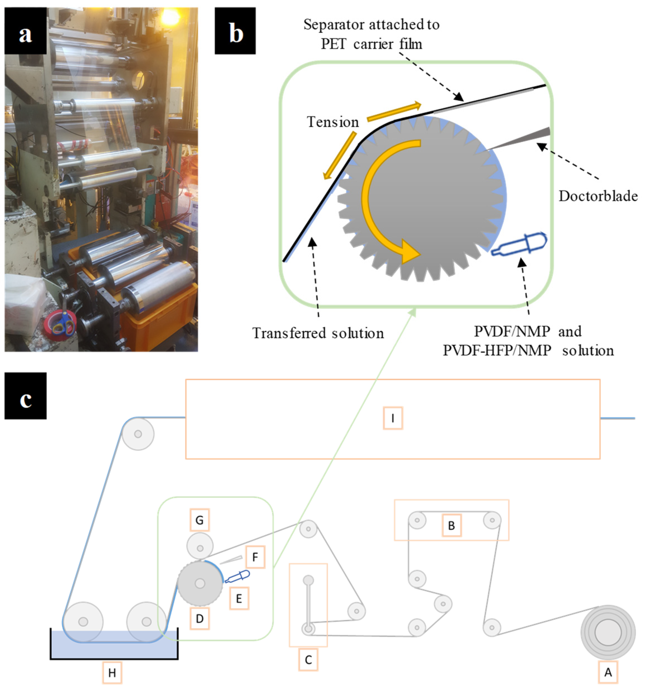
2.2. R2R Gravure Coating
2.3. Characterization of the Coated Separator
3. Results and Discussion
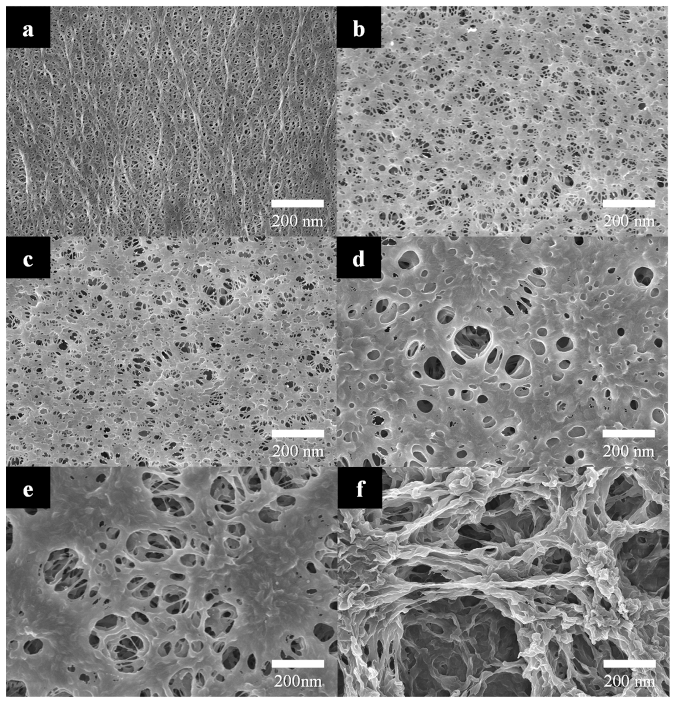
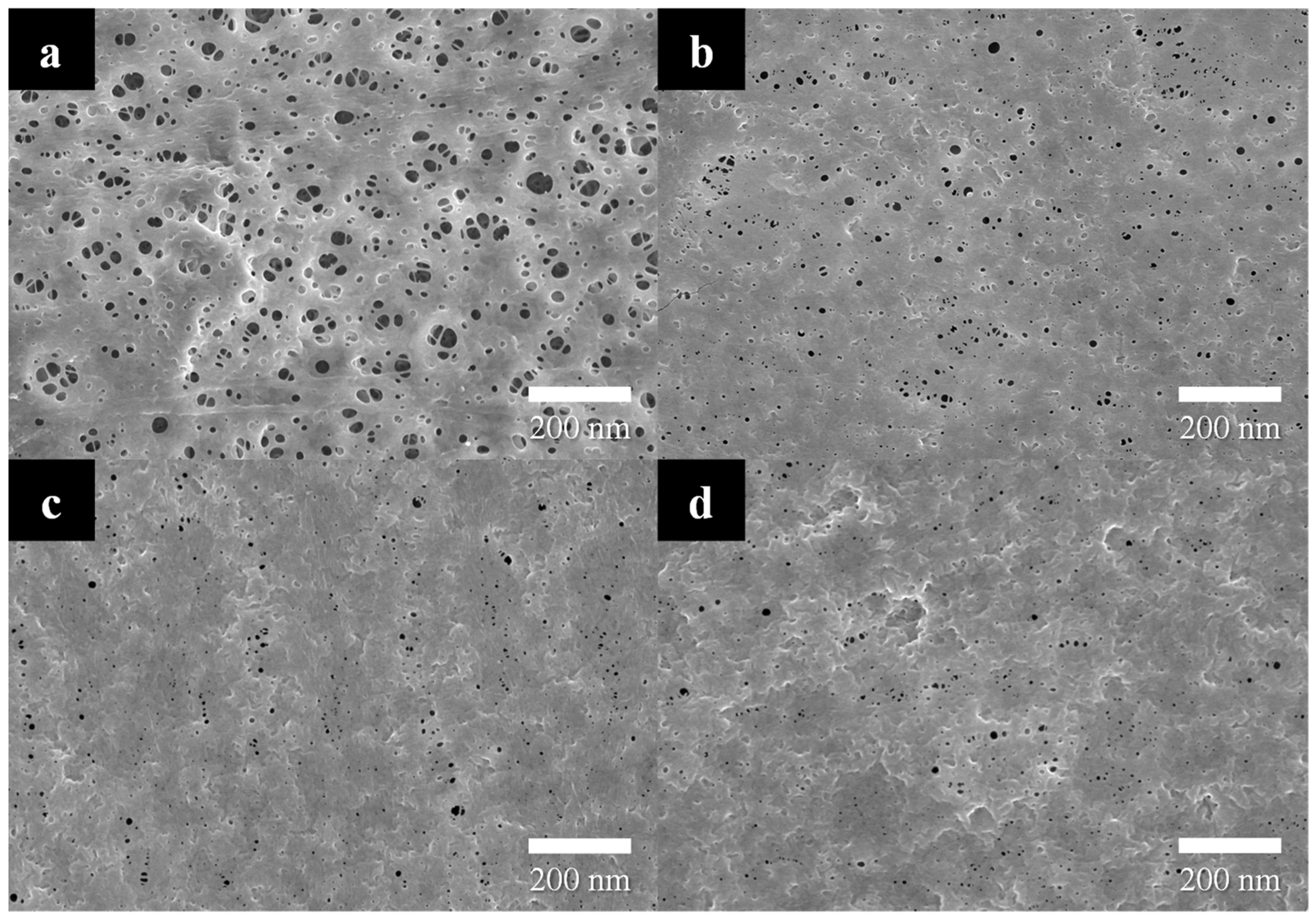
3.1. Mechanism of Nonsolvent-Induced Phase Separation (NIPS)
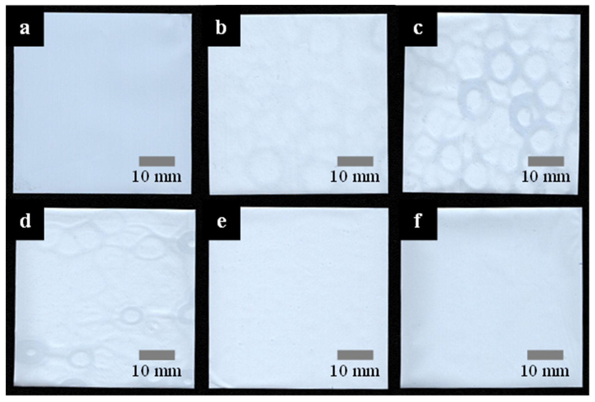
3.2. R2R Gravure-Coated Separator
3.3. Thermal Resistance
4. Conclusions
Author Contributions
Funding
Institutional Review Board Statement
Data Availability Statement
Acknowledgments
Conflicts of Interest
References
- Goodenough, J.B. How we made the Li-ion rechargeable battery. Nat. Electron. 2018, 1, 204. [Google Scholar] [CrossRef]
- Orendorff, C.J. The role of separators in lithium-ion cell safety. Electrochem. Soc. Interface 2012, 21, 61. [Google Scholar] [CrossRef]
- Gogia, A.; Wang, Y.; Rai, A.K.; Bhattacharya, R.; Subramanyam, G.; Kumar, J. Binder-free, thin-film ceramic-coated separators for improved safety of lithium-ion batteries. ACS Omega 2021, 6, 4204–4211. [Google Scholar] [CrossRef] [PubMed]
- Lin, W.; Wang, F.; Wang, H.; Li, H.; Fan, Y.; Chan, D.; Chen, S.; Tang, Y.; Zhang, Y. Thermal-Stable Separators: Design Principles and Strategies Towards Safe Lithium-Ion Battery Operations. ChemSusChem 2022, 15, e202201464. [Google Scholar] [CrossRef] [PubMed]
- Zhang, S.S. A review on the separators of liquid electrolyte Li-ion batteries. J. Power Sources 2007, 164, 351–364. [Google Scholar] [CrossRef]
- Sohn, J.Y.; Im, J.S.; Shin, J.; Nho, Y.C. PVDF-HFP/PMMA-coated PE separator for lithium ion battery. J. Solid State Electrochem. 2012, 16, 551–556. [Google Scholar] [CrossRef]
- Liu, J.; Li, W.; Zuo, X.; Liu, S.; Li, Z. Polyethylene-supported polyvinylidene fluoride–cellulose acetate butyrate blended polymer electrolyte for lithium ion battery. J. Power Sources 2013, 226, 101–106. [Google Scholar] [CrossRef]
- Gwon, S.J.; Choi, J.H.; Sohn, J.Y.; Lim, Y.M.; Nho, Y.C.; Ihm, Y.E. Battery performance of PMMA-grafted PE separators prepared by pre-irradiation grafting technique. J. Ind. Eng. Chem. 2009, 15, 748–751. [Google Scholar] [CrossRef]
- Sohn, J.Y.; Im, J.S.; Gwon, S.J.; Choi, J.H.; Shin, J.; Nho, Y.C. Preparation and characterization of a PVDF-HFP/PEGDMA-coated PE separator for lithium-ion polymer battery by electron beam irradiation. Radiat. Phys. Chem. 2009, 78, 505–508. [Google Scholar] [CrossRef]
- Lee, Y.; Ryou, M.H.; Seo, M.; Choi, J.W.; Lee, Y.M. Effect of polydopamine surface coating on polyethylene sepa-rators as a function of their porosity for high-power Li-ion batteries. Electrochim. Acta 2013, 113, 433–438. [Google Scholar] [CrossRef]
- Wang, Y.; Wang, Q.; Lan, Y.; Song, Z.; Luo, J.; Wei, X.; Sun, F.; Yue, Z.; Yin, C.; Zhou, L.; et al. Aqueous aluminide ceramic coating polyethylene sep-arators for lithium-ion batteries. Solid State Ion. 2020, 345, 115188. [Google Scholar] [CrossRef]
- Chen, X.; Chen, S.; Lin, Y.; Wu, K.; Lu, S. Multi-functional ceramic-coated separator for lithium-ion batteries safety tolerance improvement. Ceram. Int. 2020, 46, 24689–24697. [Google Scholar] [CrossRef]
- Zheng, H.; Wang, Z.; Shi, L.; Zhao, Y.; Yuan, S. Enhanced thermal stability and lithium ion conductivity of poly-ethylene separator by coating colloidal SiO2 nanoparticles with porous shell. J. Colloid Interface Sci. 2019, 554, 29–38. [Google Scholar] [CrossRef] [PubMed]
- Chen, D.; Wang, X.; Liang, J.; Zhang, Z.; Chen, W. A novel electrospinning polyacrylonitrile separator with dip-coating of zeolite and phenoxy resin for Li-ion batteries. Membranes 2021, 11, 267. [Google Scholar] [CrossRef] [PubMed]
- Zhang, J.; Liu, Z.; Kong, Q.; Zhang, C.; Pang, S.; Yue, L.; Wang, X.; Yao, J.; Cui, G. Renewable and superior thermal-resistant cel-lulose-based composite nonwoven as lithium-ion battery separator. ACS Appl. Mater. Interfaces 2013, 5, 128–134. [Google Scholar] [CrossRef] [PubMed]
- Søndergaard, R.; Hösel, M.; Angmo, D.; Larsen-Olsen, T.T.; Krebs, F.C. Roll-to-roll fabrication of polymer solar cells. Mater. Today 2012, 15, 36–49. [Google Scholar] [CrossRef]
- Hwang, K.; Jung, Y.S.; Heo, Y.J.; Scholes, F.H.; Watkins, S.E.; Subbiah, J.; Jones, D.J.; Kim, D.Y.; Vak, D. Toward large scale roll-to-roll production of fully printed perovskite solar cells. Adv. Mater. 2015, 27, 1241–1247. [Google Scholar] [CrossRef]
- Li, H.; Zuo, C.; Scully, A.D.; Angmo, D.; Yang, J.; Gao, M. Recent progress towards roll-to-roll manufacturing of perovskite solar cells using slot-die processing. Flex. Print. Electron. 2020, 5, 014006. [Google Scholar] [CrossRef]
- Jung, E.; Kim, C.; Kim, M.; Chae, H.; Cho, J.H.; Cho, S.M. Roll-to-roll preparation of silver-nanowire transparent electrode and its application to large-area organic light-emitting diodes. Org. Electron. 2017, 41, 190–197. [Google Scholar] [CrossRef]
- Tsujimura, T.; Fukawa, J.; Endoh, K.; Suzuki, Y.; Hirabayashi, K.; Mori, T. Development of flexible organic light-emitting diode on barrier film and roll-to-roll manufacturing. J. Soc. Inf. Disp. 2014, 22, 412–418. [Google Scholar] [CrossRef]
- Luo, C.; Hu, H.; Zhang, T.; Wen, S.; Wang, R.; An, Y.; Chi, S.-S.; Wang, J.; Wang, C.; Chang, J.; et al. Roll-to-Roll Fabrication of Zero-Volume-Expansion Lithium-Composite Anodes to Realize High-Energy-Density Flexible and Stable Lithium-Metal Batteries. Adv. Mater. 2022, 34, 2205677. [Google Scholar] [CrossRef] [PubMed]
- Wu, L.Y.; Kerk, W.; Wong, C.C. Transparent conductive film by large area roll-to-roll processing. Thin Solid Films 2013, 544, 427–432. [Google Scholar] [CrossRef]
- Wang, B.-Y.; Lee, E.-S.; Lim, D.-S.; Kang, H.W.; Oh, Y.-J. Roll-to-roll slot die production of 300 mm large area silver nanowire mesh films for flexible transparent electrodes. RSC Adv. 2017, 7, 7540–7546. [Google Scholar] [CrossRef]
- Jeong, H.; Noh, Y.; Kim, G.Y.; Lee, H.; Lee, D. Roll-to-roll processed silver nanowire/silicon dioxide microsphere composite for high-accuracy flexible touch sensing application. Surfaces Interfaces 2022, 30, 101976. [Google Scholar] [CrossRef]
- Deng, B.; Hsu, P.C.; Chen, G.C.; Chandrashekar, B.N.; Liao, L.; Ayitimuda, Z.; Wu, J.X.; Guo, Y.F.; Lin, L.; Zhou, Y.; et al. Roll-to-roll encapsulation of metal nanowires between graphene and plastic substrate for high-performance flexible transparent electrodes. Nano Lett. 2015, 15, 4206–4213. [Google Scholar] [CrossRef] [PubMed]
- Jeong, H.; Lee, J.H.; Song, J.-Y.; Ghani, F.; Lee, D. Continuous Patterning of Silver Nanowire-Polyvinylpyrrolidone Composite Transparent Conductive Film by a Roll-to-Roll Selective Calendering Process. Nanomaterials 2022, 13, 32. [Google Scholar] [CrossRef] [PubMed]
- García-Payo, M.D.C.; Essalhi, M.; Khayet, M. Effects of PVDF-HFP concentration on membrane distillation per-formance and structural morphology of hollow fiber membranes. J. Membr. Sci. 2010, 347, 209–219. [Google Scholar] [CrossRef]
- Jeong, H.; Noh, Y.; Lee, D. Highly stable and sensitive resistive flexible humidity sensors by means of roll-to-roll printed electrodes and flower-like TiO2 nanostructures. Ceram. Int. 2019, 45, 985–992. [Google Scholar] [CrossRef]
- Shi, C.; Dai, J.; Shen, X.; Peng, L.; Li, C.; Wang, X.; Zhang, P.; Zhao, J. A high-temperature stable ceramic-coated separator prepared with polyimide binder/Al2O3 particles for lithium-ion batteries. J. Membr. Sci. 2016, 517, 91–99. [Google Scholar] [CrossRef]
- Dehban, A.; Saeedavi, F.H.; Kargari, A. A study on the mechanism of pore formation through VIPS-NIPS technique for membrane fabrication. J. Ind. Eng. Chem. 2022, 108, 54–71. [Google Scholar] [CrossRef]
- Hansen, C.M. The Three Dimensional Solubility Parameter; Danish Technical: Copenhagen, Denmark, 1967; p. 14. [Google Scholar]
- Hong, S.; Lee, J.; Kang, H.; Lee, K. Slot-die coating parameters of the low-viscosity bulk-heterojunction materials used for polymer solarcells. Sol. Energy Mater. Sol. Cells 2013, 112, 27–35. [Google Scholar] [CrossRef]
- Ham, D.S.; Choi, W.J.; Yun, H.; Kim, M.; Yeo, D.-H.; Lee, S.; Kim, B.J.; Lee, J.H. Influence of drying conditions on device performances of antisolvent-assisted roll-to-roll slot die-coated perovskite solar cells. ACS Appl. Energy Mater. 2021, 4, 7611–7621. [Google Scholar] [CrossRef]
- Guan, K.; Zhang, L.; Wang, S.; Takagi, R.; Matsuyama, H. Controlling the formation of porous polyketone membranes via a cross-linkable alginate additive for oil-in-water emulsion separations. J. Membr. Sci. 2020, 611, 118362. [Google Scholar] [CrossRef]
- Huang, X. Separator technologies for lithium-ion batteries. J. Solid State Electrochem. 2010, 15, 649–662. [Google Scholar] [CrossRef]
- Sohn, J.Y.; Gwon, S.J.; Choi, J.H.; Shin, J.; Nho, Y.C. Preparation of polymer-coated separators using an electron beam irradiation. Nucl. Instrum. Methods Phys. Res. Sect. B Beam Interact. Mater. At. 2008, 266, 4994–5000. [Google Scholar] [CrossRef]
- Shin, W.K.; Kim, D.W. High performance ceramic-coated separators prepared with lithium ion-containing SiO2 particles for lithium-ion batteries. J. Power Sources 2013, 226, 54–60. [Google Scholar] [CrossRef]
- Tanaka, Y.; Nakanishi, H.; Saeki, S.; Yamaguchi, T. Thermal Contraction of Drawn Polyethylene Film I. An Empirical Equation for Temperature Dependence of Thermal Stress. Jpn. J. Appl. Phys. 1998, 37, 4467. [Google Scholar] [CrossRef]
- Lee, J.; Shin, K.; Lee, C. Analysis of dynamic thermal characteristic of register of roll-to-roll multi-layer printing systems. Robot. Comput.-Integr. Manuf. 2015, 35, 77–83. [Google Scholar] [CrossRef]
- Lestariningsih, T.; Sabrina, Q.; Ratri, C.R.; Nuroniah, I. Structure, thermal and electrical properties of PVDF-HFP/LiBOB solid polymer electrolyte. J. Phys. Conf. Ser. 2019, 1191, 012026. [Google Scholar] [CrossRef]


| Material | |||
|---|---|---|---|
| PVDF | 17.20 | 12.50 | 9.20 |
| N-methyl-2-pyrrolidone (NMP) | 18.00 | 12.30 | 7.20 |
| Water | 6.00 | 15.30 | 16.70 |
| Methanol | 7.42 | 6.00 | 10.90 |
| Pair of Materials | |
|---|---|
| PVDF~NMP | 2.57 |
| PVDF~Water | 23.79 |
| PVDF~Methanol | 20.68 |
| NMP~Water | 25.99 |
| NMP~Methanol | 22.39 |
| The Contents of Methanol in Coagulation Solution (%) | The Number of Pixels in Images | Average of Shrinkage Rate (%) | |
|---|---|---|---|
| Before Thermal Test | After Thermal Test | ||
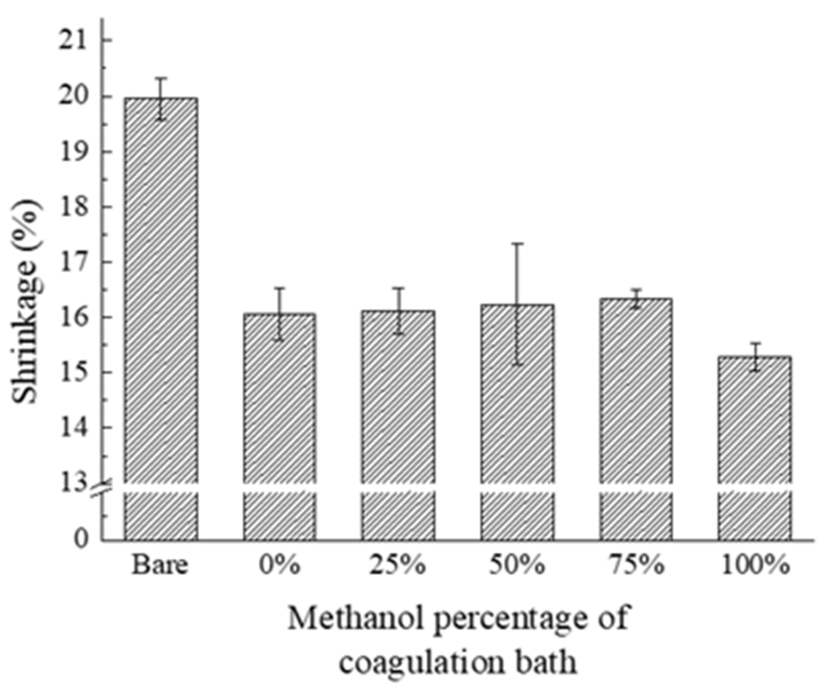
| 0 | 344,235 | 288,778 | 16.1 |
| 344,362 | 287,482 | ||
| 348,982 | 294,623 | ||
| 25 | 349,691 | 294,288 | 16.1 |
| 337,833 | 284,104 | ||
| 352,164 | 293,669 | ||
| 50 | 348,593 | 294,888 | 16.2 |
| 348,330 | 287,498 | ||
| 343,957 | 289,430 | ||
| 75 | 347,599 | 290,477 | 16.3 |
| 350,537 | 292,864 | ||
| 339,601 | 284,761 | ||
| 100 | 349,647 | 297,002 | 15.3 |
| 340,814 | 287,786 | ||
| 349,784 | 296,393 | ||
| The Concentration of PVDF-HFP in Coating Solution (wt%) | The Number of Pixels in Images | Average of Shrinkage Rate (%) | |
|---|---|---|---|
| Before Thermal Test | After Thermal Test | ||
| 10.0 | 349,207 | 290,371 | 16.8 |
| 351,605 | 292,917 | ||
| 345,130 | 286,673 | ||
| 12.5 | 348,094 | 290,186 | 16.6 |
| 349,270 | 290,566 | ||
| 350,583 | 292,922 | ||
| 15.0 | 348,842 | 294,054 | 15.8 |
| 344,439 | 288,990 | ||
| 345,627 | 291,739 | ||
| 17.5 | 346,180 | 294,262 | 15.1 |
| 347,949 | 295,925 | ||
| 346,532 | 292,946 | ||
Disclaimer/Publisher’s Note: The statements, opinions and data contained in all publications are solely those of the individual author(s) and contributor(s) and not of MDPI and/or the editor(s). MDPI and/or the editor(s) disclaim responsibility for any injury to people or property resulting from any ideas, methods, instructions or products referred to in the content. |
© 2023 by the authors. Licensee MDPI, Basel, Switzerland. This article is an open access article distributed under the terms and conditions of the Creative Commons Attribution (CC BY) license (https://creativecommons.org/licenses/by/4.0/).
Share and Cite
Kim, G.; Noh, J.-H.; Lee, H.; Shin, J.; Lee, D. Roll-to-Roll Gravure Coating of PVDF on a Battery Separator for the Enhancement of Thermal Stability. Polymers 2023, 15, 4108. https://doi.org/10.3390/polym15204108
Kim G, Noh J-H, Lee H, Shin J, Lee D. Roll-to-Roll Gravure Coating of PVDF on a Battery Separator for the Enhancement of Thermal Stability. Polymers. 2023; 15(20):4108. https://doi.org/10.3390/polym15204108
Chicago/Turabian StyleKim, Gyuyoung, Jin-Hee Noh, Horim Lee, Jaehak Shin, and Dongjin Lee. 2023. "Roll-to-Roll Gravure Coating of PVDF on a Battery Separator for the Enhancement of Thermal Stability" Polymers 15, no. 20: 4108. https://doi.org/10.3390/polym15204108