
Obtaining Cellulose Nanocrystals from Olive Tree Pruning Waste and Evaluation of Their Influence as a Reinforcement on Biocomposites
 , , and
Abstract
:1. Introduction
2. Materials and Methods
2.1. Isolation of Cellulose Content
2.2. Preparation of CNCs
2.3. Characterization of OTP Samples and CNCs
2.4. Manufacturing of Composites
2.5. Characterization of Composites
3. Results
3.1. Preparation of CNCs
3.1.1. Chemical Composition
3.1.2. Yield of the CNC Production and Morphological Characterisation
3.1.3. FT-IR
3.1.4. XRD
3.1.5. TGA
3.2. Characterisation of the Manufactured Composites
3.2.1. Mechanical Properties
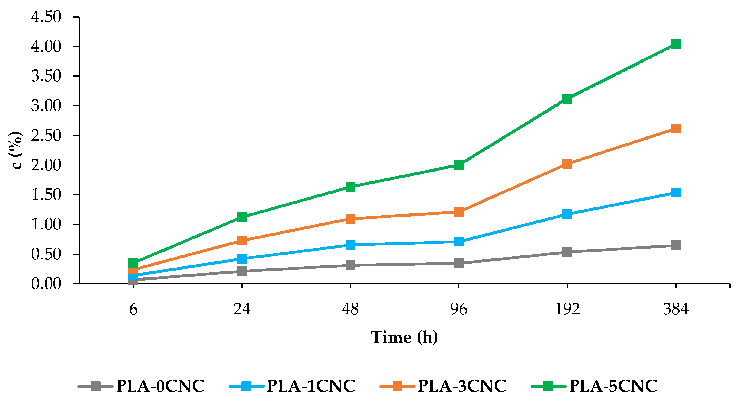
3.2.2. Water Absorption
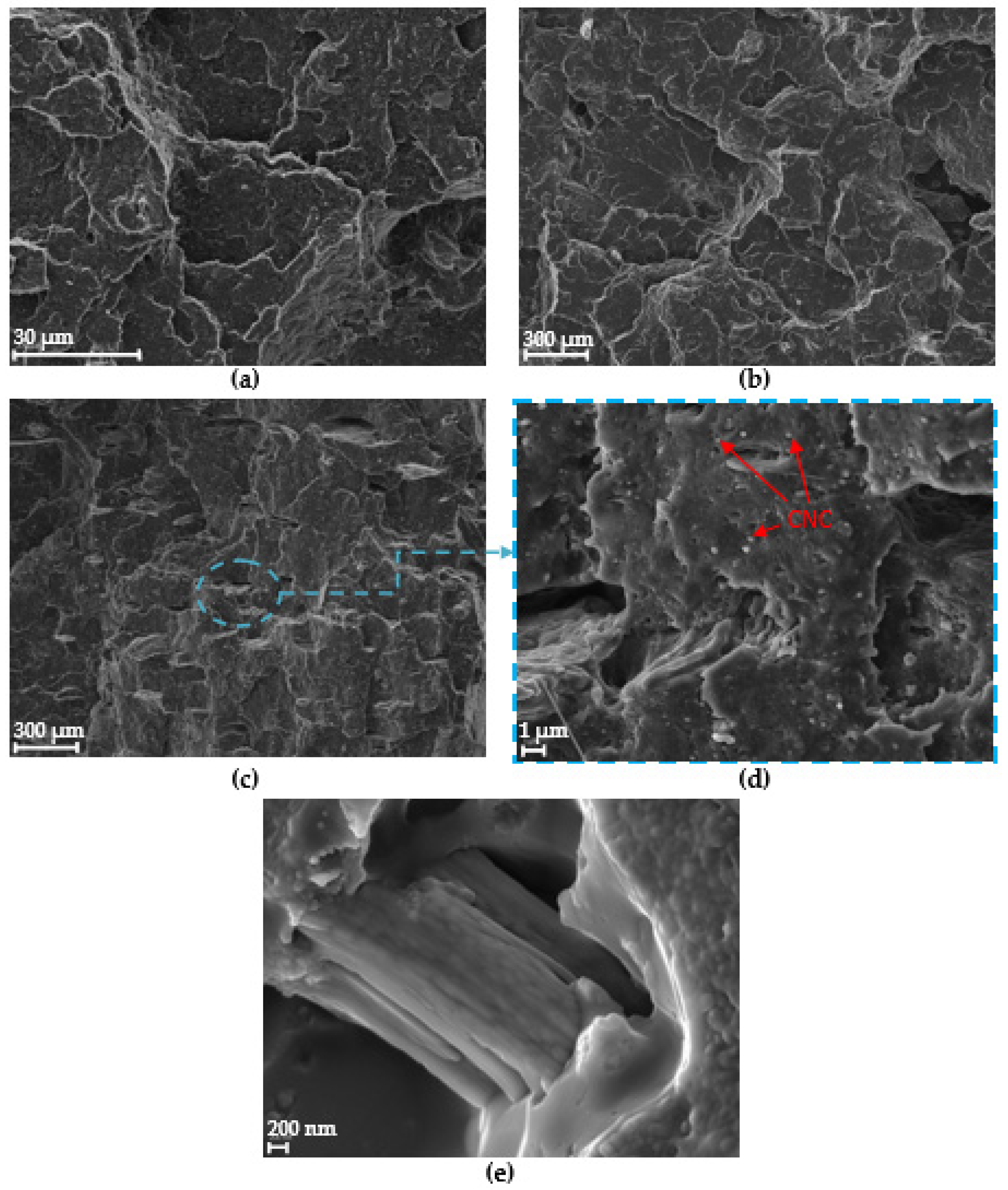
3.2.3. SEM
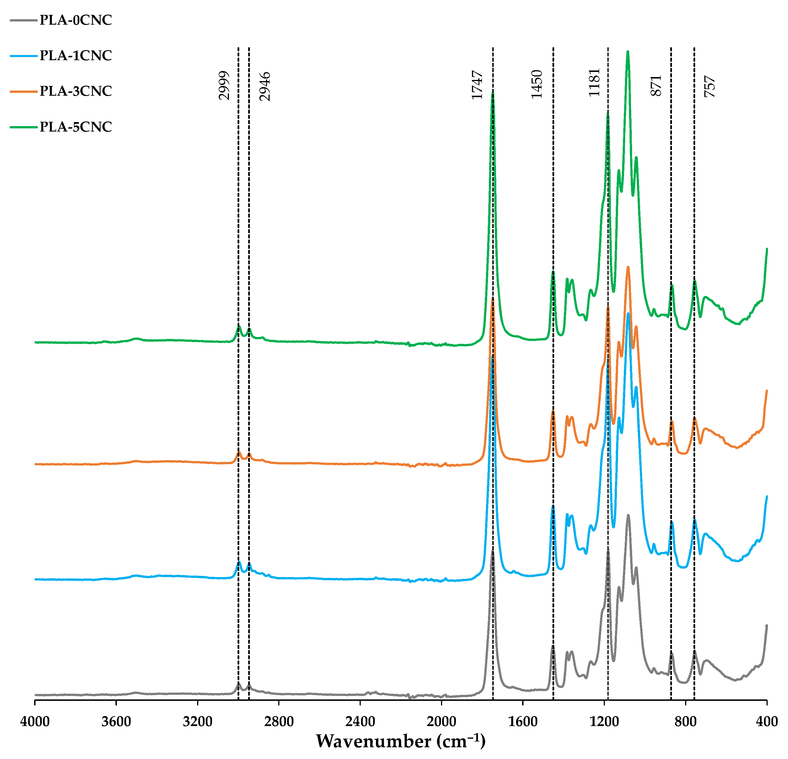
3.2.4. FT-IR
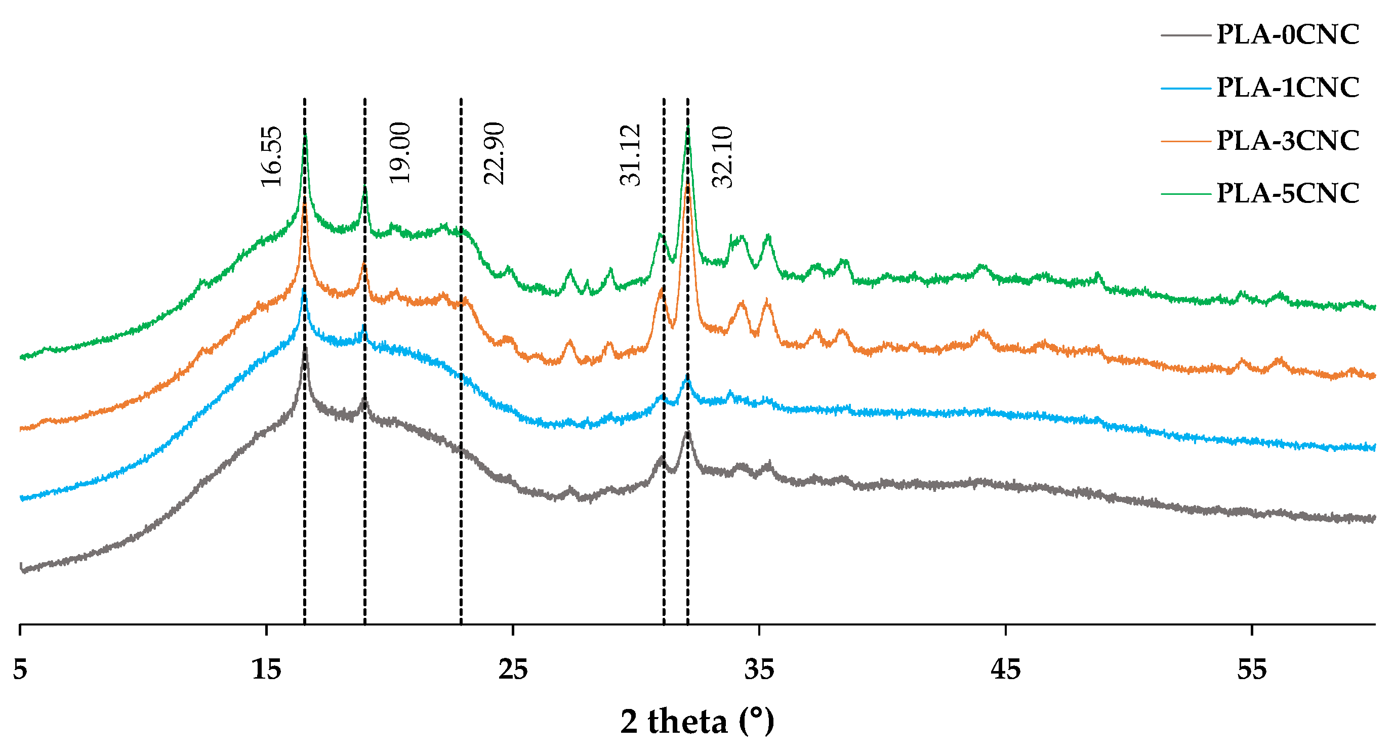
3.2.5. XRD
3.2.6. DSC
4. Conclusions
Author Contributions
Funding
Institutional Review Board Statement
Data Availability Statement
Acknowledgments
Conflicts of Interest
References
- Hassan, M.; Mustapa, I.; Daud, N.; Nahida, J.H.; Sudin, N.; Majhool, A.; Mahmoudi, E. Improvement Thermomechanical Properties of Polylactic Acid via Titania Nanofillers Reinforcement. J. Adv. Res. Fluid Mech. Therm. Sci. 2020, 70, 97–111. [Google Scholar] [CrossRef]
- Lendvai, L. Lignocellulosic Agro-Residue/Polylactic Acid (PLA) Biocomposites: Rapeseed Straw as a Sustainable Filler. Clean. Mater. 2023, 9, 100196. [Google Scholar] [CrossRef]
- Kothavade, P.; Shanmuganathan, K. Mechanical Properties of PLA/Cellulose Composites; CRC Press: Boca Raton, FL, USA, 2022; ISBN 9781003160458. [Google Scholar]
- Jurado-Contreras, S.; Navas, F.; Rodríguez-Liébana, J.; Rubia, M. Effect of Olive Pit Reinforcement in Polylactic Acid Biocomposites on Environmental Degradation. Materials 2023, 16, 5816. [Google Scholar] [CrossRef] [PubMed]
- Arora, B.; Bhatia, R.; Attri, P. 28—Bionanocomposites: Green Materials for a Sustainable Future. In New Polymer Nanocomposites for Environmental Remediation; Hussain, C.M., Mishra, A.K., Eds.; Elsevier: Amsterdam, The Netherlands, 2018; pp. 699–712. ISBN 978-0-12-811033-1. [Google Scholar]
- Kargarzadeh, H.; Huang, J.; Lin, N.; Ahmad, I.; Mariano, M.; Dufresne, A.; Thomas, S.; Gałęski, A. Recent Developments in Nanocellulose-Based Biodegradable Polymers, Thermoplastic Polymers, and Porous Nanocomposites. Prog. Polym. Sci. 2018, 87, 197–227. [Google Scholar] [CrossRef]
- Sung, S.H.; Chang, Y.; Han, J. Development of Polylactic Acid Nanocomposite Films Reinforced with Cellulose Nanocrystals Derived from Coffee Silverskin. Carbohydr. Polym. 2017, 169, 495–503. [Google Scholar] [CrossRef]
- Jonoobi, M.; Harun, J.; Mathew, A.P.; Oksman, K. Mechanical Properties of Cellulose Nanofiber (CNF) Reinforced Polylactic Acid (PLA) Prepared by Twin Screw Extrusion. Compos. Sci. Technol. 2010, 70, 1742–1747. [Google Scholar] [CrossRef]
- Fortunati, E.; Luzi, F.; Puglia, D.; Petrucci, R.; Kenny, J.M.; Torre, L. Processing of PLA Nanocomposites with Cellulose Nanocrystals Extracted from Posidonia Oceanica Waste: Innovative Reuse of Coastal Plant. Ind. Crops Prod. 2015, 67, 439–447. [Google Scholar] [CrossRef]
- Aydemir, D.; Gardner, D.J. Biopolymer Blends of Polyhydroxybutyrate and Polylactic Acid Reinforced with Cellulose Nanofibrils. Carbohydr. Polym. 2020, 250, 116867. [Google Scholar] [CrossRef]
- Isikgor, F.H.; Becer, C.R. Lignocellulosic Biomass: A Sustainable Platform for the Production of Bio-Based Chemicals and Polymers. Polym. Chem. 2015, 6, 4497–4559. [Google Scholar] [CrossRef]
- Xu, Y.; Xu, Y.; Chen, H.; Gao, M.; Yue, X.; Ni, Y. Redispersion of Dried Plant Nanocellulose: A Review. Carbohydr. Polym. 2022, 294, 119830. [Google Scholar] [CrossRef]
- Jawaid, M.; Khan, T.A.; Nasir, M.; Asim, M. Eco-Friendly Adhesives for Wood and Natural Fiber Composites: Characterization, Fabrication and Applications; Springer: Singapore, 2021; ISBN 978-981-33-4748-9. [Google Scholar]
- Kaur, M.; Sharma, P.; Kaushik, S. State of Art Manufacturing and Producing Nanocellulose from Agricultural Waste: A Review. J. Nanosci. Nanotechnol. 2021, 21, 3394–3403. [Google Scholar] [CrossRef] [PubMed]
- Klemm, D.; Kramer, F.; Moritz, S.; Lindström, T.; Ankerfors, M.; Gray, D.; Dorris, A. Nanocelluloses: A New Family of Nature-Based Materials. Angew. Chem. Int. Ed. Engl. 2011, 50, 5438–5466. [Google Scholar] [CrossRef] [PubMed]
- Zinge, C.; Kandasubramanian, B. Nanocellulose Based Biodegradable Polymers. Eur. Polym. J. 2020, 133, 109758. [Google Scholar] [CrossRef]
- Dufresne, A.; Belgacem, N. Cellulose-Reinforced Composites: From Micro-to Nanoscale. Polímeros 2010, 23, 277–286. [Google Scholar] [CrossRef]
- Abdul Khalil, H.P.S.; Davoudpour, Y.; Islam, M.N.; Mustapha, A.; Sudesh, K.; Dungani, R.; Jawaid, M. Production and Modification of Nanofibrillated Cellulose Using Various Mechanical Processes: A Review. Carbohydr. Polym. 2014, 99, 649–665. [Google Scholar] [CrossRef]
- Garavand, F.; Nooshkam, M.; Khodaei, D.; Yousefi, S.; Cacciotti, I.; Ghasemlou, M. Recent Advances in Qualitative and Quantitative Characterization of Nanocellulose-Reinforced Nanocomposites: A Review. Adv. Colloid Interface Sci. 2023, 318, 102961. [Google Scholar] [CrossRef]
- Teboho, M.; Sefadi, J.; Sadiku, R.; John, M.; Mochane, M.; Mtibe, A. Thermoplastic Processing of PLA/Cellulose Nanomaterials Composites. Polymers 2018, 10, 1363. [Google Scholar] [CrossRef]
- Trivedi, A.K.; Gupta, M.K.; Singh, H. PLA Based Biocomposites for Sustainable Products: A Review. Adv. Ind. Eng. Polym. Res. 2023, 6, 382–395. [Google Scholar] [CrossRef]
- Grishkewich, N.; Mohammed, N.; Tang, J.; Tam, K. Recent Advances in the Application of Cellulose Nanocrystals. Curr. Opin. Colloid Interface Sci. 2017, 29, 32–45. [Google Scholar] [CrossRef]
- Fonseca, B.G.; Mateo, S.; Roberto, I.C.; Sánchez, S.; Moya, A.J. Bioconversion in Batch Bioreactor of Olive-Tree Pruning Biomass Optimizing Treatments for Ethanol Production. Biochem. Eng. J. 2020, 164, 107793. [Google Scholar] [CrossRef]
- Mamaní, A.; Maturano, Y.; Mestre, V.; Montoro, L.; Gassa, L.; Deiana, C.; Sardella, F. Valorization of Olive Tree Pruning. Application for Energy Storage and Biofuel Production. Ind. Crops Prod. 2021, 173, 114082. [Google Scholar] [CrossRef]
- Zhao, T.; Chen, Z.; Lin, X.; Ren, Z.; Li, B.; Zhang, Y. Preparation and Characterization of Microcrystalline Cellulose (MCC) from Tea Waste. Carbohydr. Polym. 2018, 184, 164–170. [Google Scholar] [CrossRef] [PubMed]
- Ren, H.; Shen, J.; Pei, J.; Wang, Z.; Peng, Z.; Fu, S.; Zheng, Y. Characteristic Microcrystalline Cellulose Extracted by Combined Acid and Enzyme Hydrolysis of Sweet Sorghum. Cellulose 2019, 26, 8367–8381. [Google Scholar] [CrossRef]
- Islam, M.S.; Kao, N.; Bhattacharya, S.N.; Gupta, R.; Choi, H.J. Potential Aspect of Rice Husk Biomass in Australia for Nanocrystalline Cellulose Production. Chin. J. Chem. Eng. 2018, 26, 465–476. [Google Scholar] [CrossRef]
- García, A.; Labidi, J.; Belgacem, M.N.; Bras, J. The Nanocellulose Biorefinery: Woody versus Herbaceous Agricultural Wastes for NCC Production. Cellulose 2017, 24, 693–704. [Google Scholar] [CrossRef]
- Kian, L.K.; Saba, N.; Jawaid, M.; Alothman, O.Y.; Fouad, H. Properties and Characteristics of Nanocrystalline Cellulose Isolated from Olive Fiber. Carbohydr. Polym. 2020, 241, 116423. [Google Scholar] [CrossRef]
- Ibarra, D.; Martín-Sampedro, R.; Wicklein, B.; Fillat Latorre, U.; Eugenio, M. Production of Microfibrillated Cellulose from Fast-Growing Poplar and Olive Tree Pruning by Physical Pretreatment. Appl. Sci. 2021, 11, 6445. [Google Scholar] [CrossRef]
- Narayanan, S.; Suyambulingam, I.; Indran, D.; Siengchin, S. Comprehensive Characterization of Novel Borassus Flabellifer Flower Biomass Based Microcrystalline Cellulose Reinforced with Polylactic Acid (PLA) Biofilm for Futuristic Applications. Biomass Convers. Biorefin. 2023, 1–18. [Google Scholar] [CrossRef]
- Yan, Y.-F.; Liang, X.-B.; Feng, Y.-L.; Shi, L.-F.; Chen, R.-P.; Guo, J.-Z.; Guan, Y. Manipulation of Crystallization Nucleation and Thermal Degradation of PLA Films by Multi-Morphologies CNC-ZnO Nanoparticles. Carbohydr. Polym. 2023, 320, 121251. [Google Scholar] [CrossRef]
- Özdemir, B.; Nofar, M. Effect of Solvent Type on the Dispersion Quality of Spray-and Freeze-Dried CNCs in PLA through Rheological Analysis. Carbohydr. Polym. 2021, 268, 118243. [Google Scholar] [CrossRef]
- Eyholzer, C.; Tingaut, P.; Zimmermann, T.; Oksman, K. Dispersion and Reinforcing Potential of Carboxymethylated Nanofibrillated Cellulose Powders Modified with 1-Hexanol in Extruded Poly(Lactic Acid) (PLA) Composites. J. Polym. Environ. 2012, 20, 1052–1062. [Google Scholar] [CrossRef]
- Okubo, K.; Fujii, T.; Thostenson, E.T. Multi-Scale Hybrid Biocomposite: Processing and Mechanical Characterization of Bamboo Fiber Reinforced PLA with Microfibrillated Cellulose. Compos. Part A Appl. Sci. Manuf. 2009, 40, 469–475. [Google Scholar] [CrossRef]
- Rodríguez-Liébana, J.A.; Navas-Martos, F.J.; Jurado-Contreras, S.; Morillas-Gutiérrez, F.; Mateo, S.; Moya, A.J.; La Rubia, M.D. Manufacture and Characterisation of Polylactic Acid Biocomposites with High-Purity Cellulose Isolated from Olive Pruning Waste. J. Reinf. Plast. Compos. 2023, 07316844231162286. [Google Scholar] [CrossRef]
- Browning, B.L. The Determination of Lignin. In Methods of Wood Chemistry; Browning, B.L., Ed.; Wiley & Sons: New York, NY, USA, 1967; Volume I, pp. 785–823. [Google Scholar]
- Segal, L.; Creely, J.; Martin, A.E.J.; Conrad, C. An Empirical Method for Estimating the Degree of Crystallinity of Native Cellulose Using the X-Ray Diffractometer. Text. Res. J. 1959, 29, 786–794. [Google Scholar] [CrossRef]
- ISO 527-2:2012; Plastics—Determination of Tensile Properties—Part 2: Test Conditions for Moulding and Extrusion Plastics. ISO: Geneva, Switzerland, 2012.
- ISO 179-1:2023; Plastics—Determination of Charpy Impact Properties—Part 1: Non-Instrumented Impact Test. ISO: Geneva, Switzerland, 2023.
- ISO 62:2008; Plastics—Determination of Water Absorption. ISO: Geneva, Switzerland, 2008.
- Fehri, S.; Cinelli, P.; Coltelli, M.; Anguillesi, I.; Lazzeri, A. Thermal Properties of Plasticized Poly (Lactic Acid) (PLA) Containing Nucleating Agent. Int. J. Chem. Eng. Appl. 2016, 7, 85–88. [Google Scholar] [CrossRef]
- Valvez, S.; Maceiras, A.; Santos, P.; Reis, P.N.B. Olive Stones as Filler for Polymer-Based Composites: A Review. Materials 2021, 14, 845. [Google Scholar] [CrossRef]
- Luzi, F.; Puglia, D.; Sarasini, F.; Tirillò, J.; Maffei, G.; Zuorro, A.; Lavecchia, R.; Kenny, J.M.; Torre, L. Valorization and Extraction of Cellulose Nanocrystals from North African Grass: Ampelodesmos Mauritanicus (Diss). Carbohydr. Polym. 2019, 209, 328–337. [Google Scholar] [CrossRef]
- Kumar, A.; Negi, Y.; Choudhary, V.; Bhardwaj, N. Characterization of Cellulose Nanocrystals Produced by Acid-Hydrolysis from Sugarcane Bagasse as Agro-Waste. J. Mater. Phys. Chem. 2014, 2, 1–8. [Google Scholar] [CrossRef]
- Akatan, K.; Kabdrakhmanova, S.; Kuanyshbekov, T.; Ibraeva, Z.; Battalova, A.; Joshy, K.S.; Thomas, S. Highly-Efficient Isolation of Microcrystalline Cellulose and Nanocellulose from Sunflower Seed Waste via Environmentally Benign Method. Cellulose 2022, 29, 3787–3802. [Google Scholar] [CrossRef]
- Morais, J.P.S.; de Freitas Rosa, M.; Nascimento, L.D.; Do Nascimento, D.M.; Cassales, A.R. Extraction and Characterization of Nanocellulose Structures from Raw Cotton Linter. Carbohydr. Polym. 2013, 91, 229–235. [Google Scholar] [CrossRef]
- Silvério, H.A.; Flauzino Neto, W.P.; Dantas, N.O.; Pasquini, D. Extraction and Characterization of Cellulose Nanocrystals from Corncob for Application as Reinforcing Agent in Nanocomposites. Ind. Crops Prod. 2013, 44, 427–436. [Google Scholar] [CrossRef]
- Costa, L.A.; Assis, D.D.J.; Gomes, G.V.; da Silva, J.B.; Fonsêca, A.F.; Druzian, J.I. Extraction and Characterization of Nanocellulose from Corn Stover. Mater. Today Proc. 2015, 2, 287–294. [Google Scholar] [CrossRef]
- Mandal, A.; Chakrabarty, D. Isolation of Nanocellulose from Waste Sugarcane Bagasse (SCB) and Its Characterization. Carbohydr. Polym. 2011, 86, 1291–1299. [Google Scholar] [CrossRef]
- Frone, A.N.; Chiulan, I.; Panaitescu, D.M.; Nicolae, C.A.; Ghiurea, M.; Galan, A.-M. Isolation of Cellulose Nanocrystals from Plum Seed Shells, Structural and Morphological Characterization. Mater. Lett. 2017, 194, 160–163. [Google Scholar] [CrossRef]
- Jiang, F.; Hsieh, Y.-L. Chemically and Mechanically Isolated Nanocellulose and Their Self-Assembled Structures. Carbohydr. Polym. 2013, 95, 32–40. [Google Scholar] [CrossRef] [PubMed]
- Singh, H.; Kumar Verma, A.; Kumar Trivedi, A.; Gupta, M.K. Characterization of Nanocellulose Isolated from Bamboo Fibers. Mater. Today Proc. 2023, in press. [CrossRef]
- Dhali, K.; Daver, F.; Cass, P.; Adhikari, B. Isolation and Characterization of Cellulose Nanomaterials from Jute Bast Fibers. J. Environ. Chem. Eng. 2021, 9, 106447. [Google Scholar] [CrossRef]
- Chirayil, C.J.; Joy, J.; Mathew, L.; Mozetic, M.; Koetz, J.; Thomas, S. Isolation and Characterization of Cellulose Nanofibrils from Helicteres Isora Plant. Ind. Crops Prod. 2014, 59, 27–34. [Google Scholar] [CrossRef]
- Gao, A.; Chen, H.; Tang, J.; Xie, K.; Hou, A. Efficient Extraction of Cellulose Nanocrystals from Waste Calotropis Gigantea Fiber by SO42-/TiO2 Nano-Solid Superacid Catalyst Combined with Ball Milling Exfoliation. Ind. Crops Prod. 2020, 152, 112524. [Google Scholar] [CrossRef]
- Wang, L.; Zhu, X.; Chen, X.; Zhang, Y.; Yang, H.; Li, Q.; Jiang, J. Isolation and Characteristics of Nanocellulose from Hardwood Pulp via Phytic Acid Pretreatment. Ind. Crops Prod. 2022, 182, 114921. [Google Scholar] [CrossRef]
- Theivasanthi, T.; Anne Christma, F.L.; Toyin, A.J.; Gopinath, S.C.B.; Ravichandran, R. Synthesis and Characterization of Cotton Fiber-Based Nanocellulose. Int. J. Biol. Macromol. 2018, 109, 832–836. [Google Scholar] [CrossRef] [PubMed]
- Foo, M.L.; Ooi, C.W.; Tan, K.W.; Chew, I.M.L. A Step Closer to Sustainable Industrial Production: Tailor the Properties of Nanocrystalline Cellulose from Oil Palm Empty Fruit Bunch. J. Environ. Chem. Eng. 2020, 8, 104058. [Google Scholar] [CrossRef]
- Kassab, Z.; Abdellaoui, Y.; Salim, M.H.; Bouhfid, R.; Qaiss, A.E.K.; El Achaby, M. Micro- and Nano-Celluloses Derived from Hemp Stalks and Their Effect as Polymer Reinforcing Materials. Carbohydr. Polym. 2020, 245, 116506. [Google Scholar] [CrossRef] [PubMed]
- Lee, K.-Y.; Blaker, J.J.; Bismarck, A. Surface Functionalisation of Bacterial Cellulose as the Route to Produce Green Polylactide Nanocomposites with Improved Properties. Compos. Sci. Technol. 2009, 69, 2724–2733. [Google Scholar] [CrossRef]
- Oksman, K.; Skrifvars, M.; Selin, J.-F. Natural Fibres as Reinforcement in Polylactic Acid (PLA) Composites. Compos. Sci. Technol. 2003, 63, 1317–1324. [Google Scholar] [CrossRef]
- Robles, E.; Urruzola, I.; Labidi, J.; Serrano, L. Surface-Modified Nano-Cellulose as Reinforcement in Poly(Lactic Acid) to Conform New Composites. Ind. Crops Prod. 2015, 71, 44–53. [Google Scholar] [CrossRef]
- Mulinari, D.; Voorwald, H.; Cioffi, M.O.; Rocha, G.; Silva, M. Surface Modification of Sugarcane Bagasse Cellulose and Its Effect on Mechanical and Water Absorption Properties of Sugarcane Bagasse Cellulose/HDPE Composites. Bioresources 2010, 5, 661–671. [Google Scholar] [CrossRef]
- Xu, J.; Xu, X.; Xu, C.; Jing, Y.; Shentu, B. Preparation and Characterization of Micro/Nanocellulose Reinforced PVDF/Wood Composites. Int. J. Biol. Macromol. 2022, 220, 766–774. [Google Scholar] [CrossRef]
- Tardy, B.L.; Yokota, S.; Ago, M.; Xiang, W.; Kondo, T.; Bordes, R.; Rojas, O.J. Nanocellulose–surfactant interactions. Curr. Opin. Colloid Interface Sci. 2017, 29, 57–67. [Google Scholar] [CrossRef]
- Meng, W.; Zhang, X.; Hu, X.; Liu, Y.; Zhang, J.; Qu, X.; Abdel-Magid, B. Mechanical Properties and Non-Isothermal Crystallization Kinetics of Polylactic Acid Modified by Polyacrylic Elastomers and Cellulose Nanocrystals. Polymers 2023, 15, 3767. [Google Scholar] [CrossRef]
- Haafiz, M.K.M.; Hassan, A.; Zakaria, Z.; Inuwa, I.M.; Islam, M.S.; Jawaid, M. Properties of Polylactic Acid Composites Reinforced with Oil Palm Biomass Microcrystalline Cellulose. Carbohydr. Polym. 2013, 98, 139–145. [Google Scholar] [CrossRef] [PubMed]
- Ruz-Cruz, M.A.; Herrera-Franco, P.; Flores-Johnson, E.; Moreno-Chulim, M.V.; Galera-Manzano, L.M.; Valadez, A. Thermal and Mechanical Properties of PLA-Based Multiscale Cellulosic Biocomposites. J. Mater. Res. Technol. 2022, 18, 485–495. [Google Scholar] [CrossRef]
- Voronova, M.; Surov, O.; Afineevskii, A.; Zakharov, A. Properties of Polyacrylamide Composites Reinforced by Cellulose Nanocrystals. Heliyon 2020, 6, e05529. [Google Scholar] [CrossRef] [PubMed]
- Bitinis, N.; Verdejo, R.; Bras, J.; Fortunati, E.; Kenny, J.M.; Torre, L.; López-Manchado, M.A. Poly(Lactic Acid)/Natural Rubber/Cellulose Nanocrystal Bionanocomposites Part I. Processing and Morphology. Carbohydr. Polym. 2013, 96, 611–620. [Google Scholar] [CrossRef] [PubMed]


| Composite | PLA (%wt.) | CNC (%wt.) | PA (%wt.) |
|---|---|---|---|
| PLA-0CNC | 98.5 | 0 | 1.5 |
| PLA-1CNC | 97.5 | 1 | 1.5 |
| PLA-3CNC | 95.5 | 3 | 1.5 |
| PLA-5CNC | 93.5 | 5 | 1.5 |
| Moisture (%wt.) | Ash (%wt.) | Cellulose (%wt.) | Hemicellulose (%wt.) | Lignin (%wt.) | Yield (%) | |
|---|---|---|---|---|---|---|
| OTP * | 7.00 | 0.18 | 31.50 | 21.60 | 24.80 | - |
| OTP-BH * | 3.98 | 0.03 | 83.30 | 0.50 | 5.00 | 22.9 |
| OTP-BL | 5.62 | 0.00 | 86.10 | Not detected | 3.80 | 89.7 |
| Waste | Length (nm) | Diameter (nm) | Crystallinity (%) | Degradation Temperature (°C) | Reference |
|---|---|---|---|---|---|
| Sunflower seed | 450.0 ± 50.0 | 50.0 ± 15.0 | 82.0 | 200 | [46] |
| Cotton | 177.0 | 12.0 | 90.5 | - | [47] |
| Corn | 287.3 ± 75.5 | 4.9 ± 1.3 | 79.8 | 200 | [48] |
| Corn stover | 356.3 ± 98.0 | 7.0 ± 1.9 | 55.0 | - | [49] |
| Sugarcane baggasse | 37.0–220.0 | 18.0–32.0 | - | - | [50] |
| 250.0–480.0 | 20.0–60.0 | 72.5 | 236 | [45] | |
| Plum seed shells | 100.0–800.0 | 14.0 | 54.0 | 196 | [51] |
| Rice Straw | 116.6–166.0 | 3.9–6.7 | 90.7 | - | [52] |
| Composite | σm (MPa) | σb (MPa) | εm (%) | εb (%) | Et (MPa) |
|---|---|---|---|---|---|
| PLA-0CNC | 45.42 ± 4.00 | 35.52 ± 4.65 | 4.84 ± 0.38 | 9.75 ± 1.90 | 3033.25 ± 174.26 |
| PLA-1CNC | 39.10 ± 2.97 | 31.17 ± 2.82 | 3.66 ± 0.28 | 10.52 ± 1.18 | 3770.15 ± 244.96 |
| PLA-3CNC | 41.04 ± 1.14 | 34.14 ± 1.18 | 3.48 ± 0.27 | 5.44 ± 1.03 | 4734.97 ± 229.29 |
| PLA-5CNC | 85.07 ± 5.19 | 63.97 ± 6.78 | 3.75 ± 0.34 | 8.23 ± 2.07 | 4812.18 ± 282.70 |
| Composite | Tg (°C) | Tc (°C) | Tm (°C) | ΔHc (J/g) | ΔHm (J/g) | Wc (%) |
|---|---|---|---|---|---|---|
| PLA-0CNC | 62.51 | 98.59 | 170.60 | 25.13 | 36.18 | 39.20 |
| PLA-1CNC | 62.31 | 97.94 | 169.13 | 22.35 | 37.35 | 40.89 |
| PLA-3CNC | 62.65 | 98.28 | 169.42 | 22.25 | 31.99 | 35.75 |
| PLA-5CNC | 62.81 | 98.67 | 170.27 | 20.92 | 32.85 | 37.50 |
Disclaimer/Publisher’s Note: The statements, opinions and data contained in all publications are solely those of the individual author(s) and contributor(s) and not of MDPI and/or the editor(s). MDPI and/or the editor(s) disclaim responsibility for any injury to people or property resulting from any ideas, methods, instructions or products referred to in the content. |
© 2023 by the authors. Licensee MDPI, Basel, Switzerland. This article is an open access article distributed under the terms and conditions of the Creative Commons Attribution (CC BY) license (https://creativecommons.org/licenses/by/4.0/).
Share and Cite
Jurado-Contreras, S.; Navas-Martos, F.J.; García-Ruiz, Á.; Rodríguez-Liébana, J.A.; La Rubia, M.D. Obtaining Cellulose Nanocrystals from Olive Tree Pruning Waste and Evaluation of Their Influence as a Reinforcement on Biocomposites. Polymers 2023, 15, 4251. https://doi.org/10.3390/polym15214251
Jurado-Contreras S, Navas-Martos FJ, García-Ruiz Á, Rodríguez-Liébana JA, La Rubia MD. Obtaining Cellulose Nanocrystals from Olive Tree Pruning Waste and Evaluation of Their Influence as a Reinforcement on Biocomposites. Polymers. 2023; 15(21):4251. https://doi.org/10.3390/polym15214251
Chicago/Turabian StyleJurado-Contreras, Sofía, Francisco J. Navas-Martos, Ángeles García-Ruiz, José A. Rodríguez-Liébana, and M. Dolores La Rubia. 2023. "Obtaining Cellulose Nanocrystals from Olive Tree Pruning Waste and Evaluation of Their Influence as a Reinforcement on Biocomposites" Polymers 15, no. 21: 4251. https://doi.org/10.3390/polym15214251