
Improving the Corrosion Resistance of Zn-Rich Epoxy Coating with Three-Dimensional Porous Graphene


Abstract
:1. Introduction
2. Materials and Methods
2.1. Materials
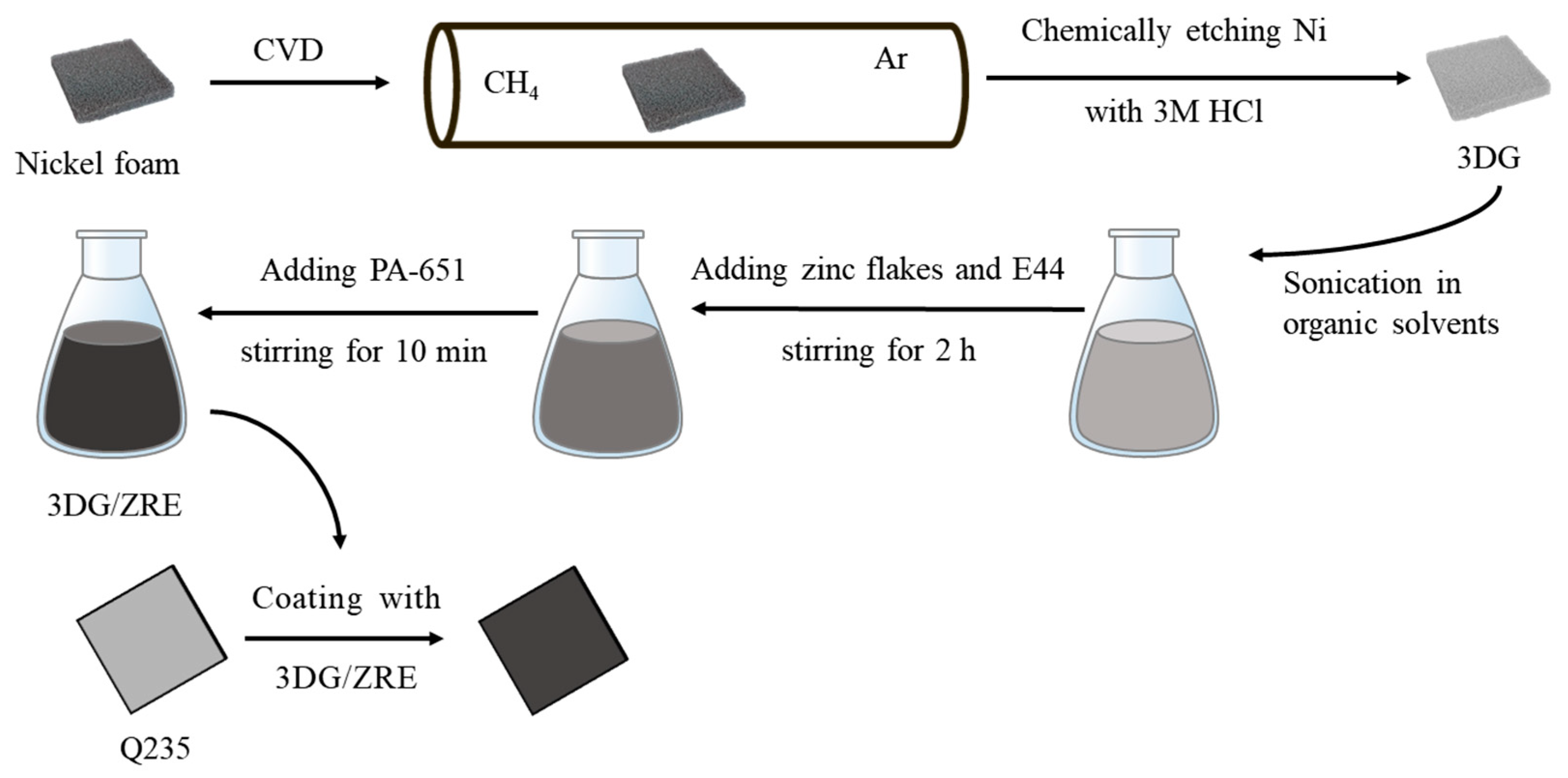
2.2. Preparation of Composite Paint and Coating Samples
2.3. Characterization Methods
3. Results and Discussion
3.1. Structure Characterization of G and 3DG
3.2. Corrosion Inhibition of the Coatings
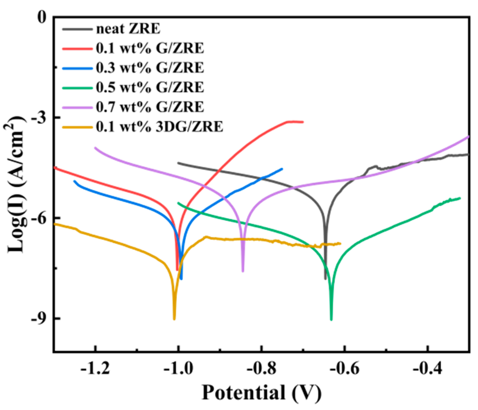
3.2.1. Corrosion Inhibition of Graphene Modified ZRE Coatings
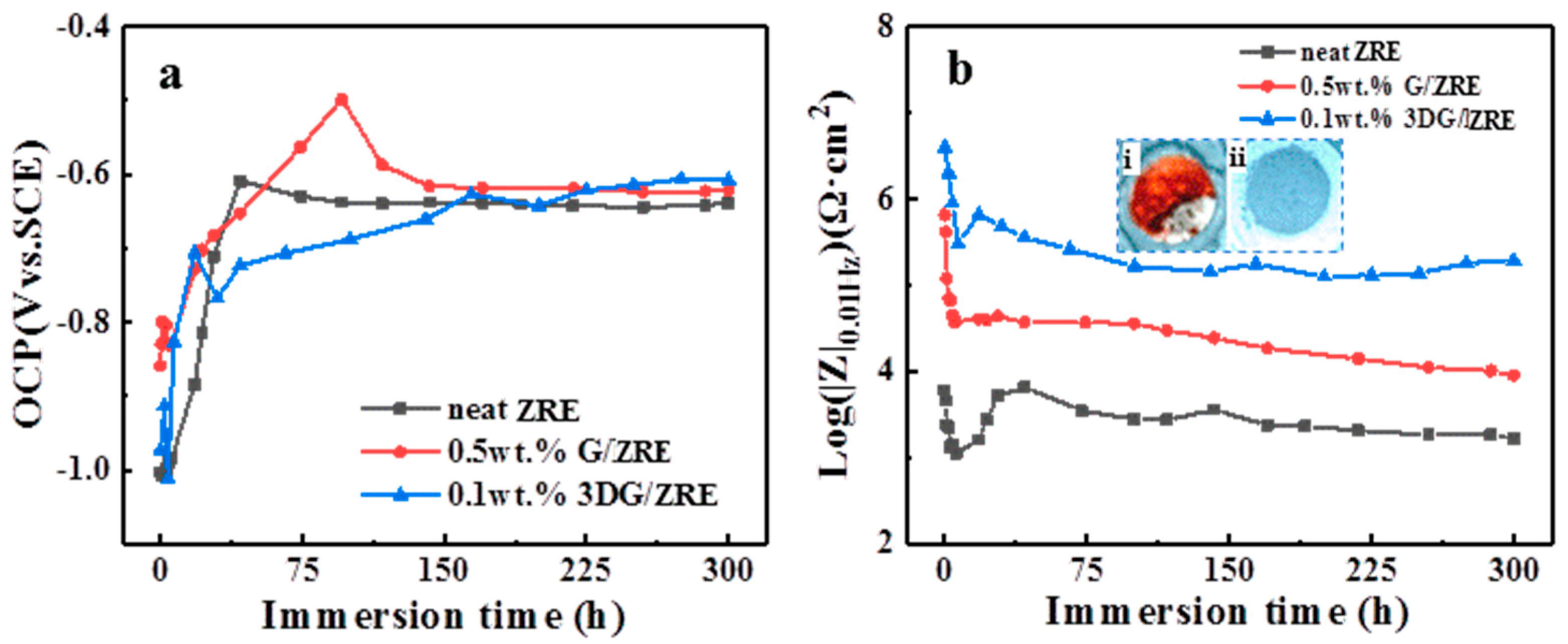
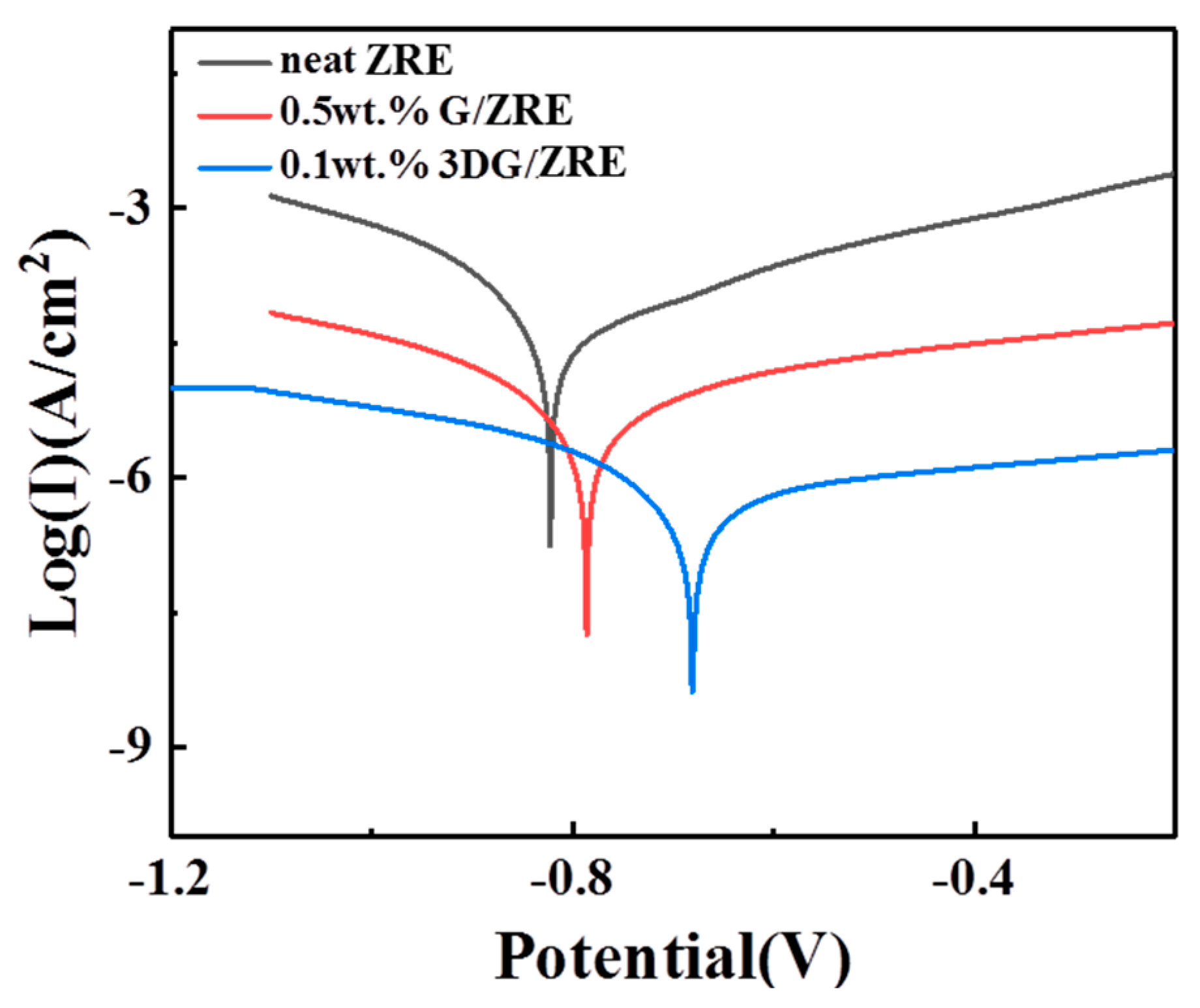
3.2.2. Corrosion Resistance of 3DG Modified ZRE Coatings
4. Conclusions
- (1)
- The corrosion resistance of the ZRE coating could be improved by incorporating common 2D graphene, and the optimal G content is 0.5 wt%.
- (2)
- The corrosion resistance of the ZRE coating could be further enhanced significantly by incorporating only 0.1 wt% 3DG.
- (3)
- Long-term immersion tests confirmed the superior effect of 3DG on improving the surface protection performance of ZRE as well.
Author Contributions
Funding
Institutional Review Board Statement
Data Availability Statement
Acknowledgments
Conflicts of Interest
References
- Ghasali, E.; Orooji, Y.; Azarniya, A.; Alizadeh, M.; Kazem-zad, M.; Ebadzadeh, T. Production of V2C MXene using a repetitive pattern of V2AlC MAX phase through microwave heating of Al-V2O5-C system. Appl. Surf. Sci. 2021, 542, 148538. [Google Scholar] [CrossRef]
- Zhang, F.; Yang, K.; Liu, G.; Chen, Y.; Wang, M.; Li, S.; Li, R. Recent advances on graphene: Synthesis, properties and applications. Compos. Part A Appl. Sci. Manuf. 2022, 160, 107051. [Google Scholar] [CrossRef]
- Guo, F.; Li, L.; Shi, Y.; Shi, W.; Yang, X.; Li, H. Achieving superior anticorrosion and antibiofouling performance of polyaniline/graphitic carbon nitride composite coating. Prog. Org. Coat. 2023, 179, 107512. [Google Scholar] [CrossRef]
- Shen, L.; Zhao, W.; Miao, L. Designed a novel EP plus GO/ZRC plus GO coating with bilayered structure for enhancing corrosion resistance of steel substrate. J. Hazard. Mater. 2021, 403, 123670. [Google Scholar] [CrossRef] [PubMed]
- Xu, X.; Yi, D.; Wang, Z.; Yu, J.; Zhang, Z.; Qiao, R.; Sun, Z.; Hu, Z.; Gao, P.; Peng, H.; et al. Greatly Enhanced Anticorrosion of Cu by Commensurate Graphene Coating. Adv. Mater. 2018, 30, 1702944. [Google Scholar] [CrossRef] [PubMed]
- Wang, X.; Zou, J.; Du, X.S. Facile flame catalytic growing carbon coating on Cu panel with surface protection performance comparable to that of graphene film via CVD. Surf. Coat. Technol. 2022, 445, 128720. [Google Scholar] [CrossRef]
- Zou, J.; Wang, X.; Zhang, P.; Du, X. Ultrafast flame coating of carbon and chemical vapor deposition of graphene on NiTi alloy to enhance its corrosion resistance. Diam. Relat. Mater. 2022, 128, 109231. [Google Scholar] [CrossRef]
- Cui, G.; Bi, Z.; Zhang, R.; Liu, J.; Yu, X.; Li, Z. A comprehensive review on graphene-based anti-corrosive coatings. Chem. Eng. J. 2019, 373, 104–121. [Google Scholar] [CrossRef]
- Ding, R.; Zheng, Y.; Yu, H.; Li, W.; Wang, X.; Gui, T. Study of water permeation dynamics and anti-corrosion mechanism of graphene/zinc coatings. J. Alloys Compd. 2018, 748, 481–495. [Google Scholar] [CrossRef]
- Halkjær, S.; Iversen, J.; Kyhl, L.; Chevallier, J.; Andreatta, F.; Yu, F.; Stoot, A.; Camilli, L.; Bøggild, P.; Hornekær, L. Low-temperature synthesis of a graphene-based, corrosion-inhibiting coating on an industrial grade alloy. Corros. Sci. 2019, 152, 1–9. [Google Scholar] [CrossRef]
- Cheng, L.; Liu, C.; Han, D.; Ma, S.; Guo, W.; Cai, H.; Wang, X. Effect of graphene on corrosion resistance of waterborne inorganic zinc-rich coatings. J. Alloys Compd. 2019, 774, 255–264. [Google Scholar] [CrossRef]
- Shen, L.; Li, Y.; Zhao, W.; Miao, L.; Xie, W.; Lu, H.; Wang, K. Corrosion Protection of Graphene-Modified Zinc-Rich Epoxy Coatings in Dilute NaCl Solution. ACS Appl. Nano Mater. 2019, 2, 180–190. [Google Scholar] [CrossRef]
- Huang, S.; Kong, G.; Yang, B.; Zhang, S.; Che, C. Effects of graphene on the corrosion evolution of zinc particles in waterborne epoxy zinc-containing coatings. Prog. Org. Coat. 2020, 140, 105531. [Google Scholar] [CrossRef]
- Cao, X.; Huang, F.; Huang, C.; Liu, J.; Cheng, Y.F. Preparation of graphene nanoplate added zinc-rich epoxy coatings for enhanced sacrificial anode-based corrosion protection. Corros. Sci. 2019, 159, 108120. [Google Scholar] [CrossRef]
- Ding, R.; Li, W.; Wang, X.; Gui, T.; Li, B.; Han, P.; Tian, H.; Liu, A.; Wang, X.; Liu, X.; et al. A brief review of corrosion protective films and coatings based on graphene and graphene oxide. J. Alloys Compd. 2018, 764, 1039–1055. [Google Scholar] [CrossRef]
- Ge, T.; Zhao, W.; Wu, X.; Lan, X.; Zhang, Y.; Qiang, Y.; He, Y. Incorporation of electroconductive carbon fibers to achieve enhanced anti-corrosion performance of zinc rich coatings. J. Colloid Interface Sci. 2020, 567, 113–125. [Google Scholar] [CrossRef]
- Cho, S.; Chiu, T.M.; Castaneda, H. Electrical and electrochemical behavior of a zinc-rich epoxy coating system with carbon nanotubes as a diode-like material. Electrochim. Acta 2019, 316, 189–201. [Google Scholar] [CrossRef]
- Zhou, S.; Wu, Y.; Zhao, W.; Yu, J.; Jiang, F.; Wu, Y.; Ma, L. Designing reduced graphene oxide/zinc rich epoxy composite coatings for improving the anticorrosion performance of carbon steel substrate. Mater. Des. 2019, 169, 107694. [Google Scholar] [CrossRef]
- Dutta, G.K.; Karak, N. Bio-based waterborne polyester/cellulose nanofiber-reduced graphene oxide-zinc oxide nanocomposite: An approach towards sustainable mechanically robust anticorrosive coating. Cellulose 2022, 29, 1679–1703. [Google Scholar] [CrossRef]
- Wu, Y.; Zhao, W.; Qiang, Y.; Chen, Z.; Wang, L.; Gao, X.; Fang, Z. π-π interaction between fluorinated reduced graphene oxide and acridizinium ionic liquid: Synthesis and anti-corrosion application. Carbon 2020, 159, 292–302. [Google Scholar] [CrossRef]
- Cui, M.; Ren, S.; Zhao, H.; Xue, Q.; Wang, L. Polydopamine coated graphene oxide for anticorrosive reinforcement of water-borne epoxy coating. Chem. Eng. J. 2018, 335, 255–266. [Google Scholar] [CrossRef]
- Li, Z.; Wang, X.; Zhang, Y.; Jing, C. Enhancing the Corrosion Resistance of Epoxy Coatings by Impregnation with a Reduced Graphene Oxide-Hydrophobic Ionic Liquid Composite. ChemElectroChem 2018, 5, 3300–3306. [Google Scholar] [CrossRef]
- Parhizkar, N.; Shahrabi, T.; Ramezanzadeh, B. A new approach for enhancement of the corrosion protection properties and interfacial adhesion bonds between the epoxy coating and steel substrate through surface treatment by covalently modified amino functionalized graphene oxide film. Corros. Sci. 2017, 123, 55–75. [Google Scholar] [CrossRef]
- Du, X.; Liu, H.Y.; Mai, Y.-W. Ultrafast Synthesis of Multifunctional NDoped Graphene Foam in an Ethanol Flame. ACS Nano 2016, 10, 453–462. [Google Scholar] [CrossRef] [PubMed]
- Zhou, H.; Wang, H.; Du, X.; Zhang, Y.; Zhou, H.; Yuan, H.; Liu, H.-Y.; Mai, Y.-W. Facile fabrication of large 3D graphene filler modified epoxy composites with improved thermal conduction and tribological performance. Carbon 2018, 139, 1168–1177. [Google Scholar] [CrossRef]
- Zhou, H.; Wang, H.; Du, X.; Mo, Y.; Yuan, H.; Liu, H.-Y. Hybrid three-dimensional graphene fillers and graphite platelets to improve the thermal conductivity and wear performance of epoxy composites. Compos. Part A 2019, 123, 270–277. [Google Scholar] [CrossRef]
- Meng, W.; Du, X.; Ma, C.; Li, W. Highly Sensitive Flexible Poly(dimethylsiloxane) Composite Sensors Based on Flame-Synthesized Carbon Foam Made of Vertical Carbon Nanosheet Arrays. ACS Sustain. Chem. Eng 2020, 8, 14091–14100. [Google Scholar] [CrossRef]
- Meng, W.; Zou, J.; Wang, X.; Zhang, P.; Du, X. On the Distinctive Hardness, Anti-Corrosion Properties and Mechanisms of Flame-Deposited Carbon Coating with a Hierarchical Structure in Contrast to a Graphene Layer via Chemical Vapor Deposition. Nanomaterials 2022, 12, 2944. [Google Scholar] [CrossRef]
- Ferrari, A.C.; Meyer, J.C.; Scardaci, V.; Casiraghi, C.; Lazzeri, M.; Mauri, F.; Piscanec, S.; Jiang, D.; Novoselov, K.S.; Roth, S.; et al. Raman spectrum of graphene and graphene layers. Phys. Rev. Lett. 2006, 97, 187401. [Google Scholar] [CrossRef]
- Teng, S.; Gao, Y.; Cao, F.; Kong, D.; Zheng, X.; Ma, X.; Zhi, L. Zinc-reduced graphene oxide for enhanced corrosion protection of zinc-rich epoxy coatings. Prog. Org. Coat. 2018, 123, 185–189. [Google Scholar] [CrossRef]
- Ramezanzadeh, B.; Mohamadzadeh Moghadam, M.H.; Shohani, N.; Mahdavian, M. Effects of highly crystalline and conductive polyaniline/graphene oxide composites on the corrosion protection performance of a zinc-rich epoxy coating. Chem. Eng. J. 2017, 320, 363–375. [Google Scholar] [CrossRef]
- Mo, M.; Zhao, W.; Chen, Z.; Yu, Q.; Zeng, Z.; Wu, X.; Xue, Q. Excellent tribological and anti-corrosion performance of polyurethane composite coatings reinforced with functionalized graphene and graphene oxide nanosheets. RSC Adv. 2015, 5, 56486–56497. [Google Scholar] [CrossRef]
- Yun, T.H.; Park, J.H.; Kim, J.S.; Park, J.M. Effect of the surface modification of zinc powders with organosilanes on the corrosion resistance of a zinc pigmented organic coating, Prog. Org. Coat. 2014, 77, 1780–1788. [Google Scholar] [CrossRef]
- Mouanga, M.; Berçot, P.; Rauch, J.Y. Comparison of corrosion behaviour of zinc in NaCl and in NaOH solutions. Part I: Corrosion layer characterization. Corros. Sci. 2010, 52, 3984–3992. [Google Scholar] [CrossRef]
- De la Fuente, D.; Castaño, J.G.; Morcillo, M. Long-term atmospheric corrosion of zinc. Corros. Sci. 2007, 49, 1420–1436. [Google Scholar] [CrossRef]
- Li, X.; Cubides, Y.; He, Z.; Soucek, M.D.; Castaneda, H. Corrosion Assessment of Zinc-Rich Primers Containing Polyaniline and the Effect of Acid as a Dopant. Corrosion 2018, 74, 1141–1157. [Google Scholar] [CrossRef]
- Xie, D.-M.; Huang, K.; Feng, X.; Wang, Y.-G. Improving the performance of zinc-rich coatings using conductive pigments and silane, Corrosion Engineering. Sci. Technol. 2020, 55, 539–549. [Google Scholar]


| ZRE Samples | Icorr (A·cm−2) | Ecorr (V) | Rpo (Ω·cm2) |
|---|---|---|---|
| neat ZRE | 6.11 × 10⁻⁶ | −0.646 | 5.67 × 10³ |
| 0.1 wt% G/ZRE | 1.95 × 10⁻⁶ | −1.002 | 1.31 × 10⁴ |
| 0.3 wt% G/ZRE | 1.15 × 10⁻⁶ | −0.993 | 3.21 × 10⁴ |
| 0.5 wt% G/ZRE | 7.14 × 10⁻⁷ | −0.631 | 3.65 × 10⁵ |
| 0.7 wt% G/ZRE | 3.36 × 10⁻⁶ | −0.844 | 1.27 × 10⁴ |
| 0.1 wt% 3DG/ZRE | 1.90 × 10⁻⁷ | −1.010 | 5.04 × 10⁵ |
| Samples Soaking for 300 h | Icorr (A·cm−2) | Ecorr (V) | Rpo (Ω·cm2) |
|---|---|---|---|
| neat ZRE | 4.87 × 10⁻⁵ | −0.824 | 7.76 × 10² |
| 0.5 wt% G/ZRE | 4.02 × 10⁻⁶ | −0.786 | 9.89 × 10³ |
| 0.1 wt% 3DG/ZRE | 5.20 × 10⁻⁷ | −0.681 | 8.98 × 10⁴ |
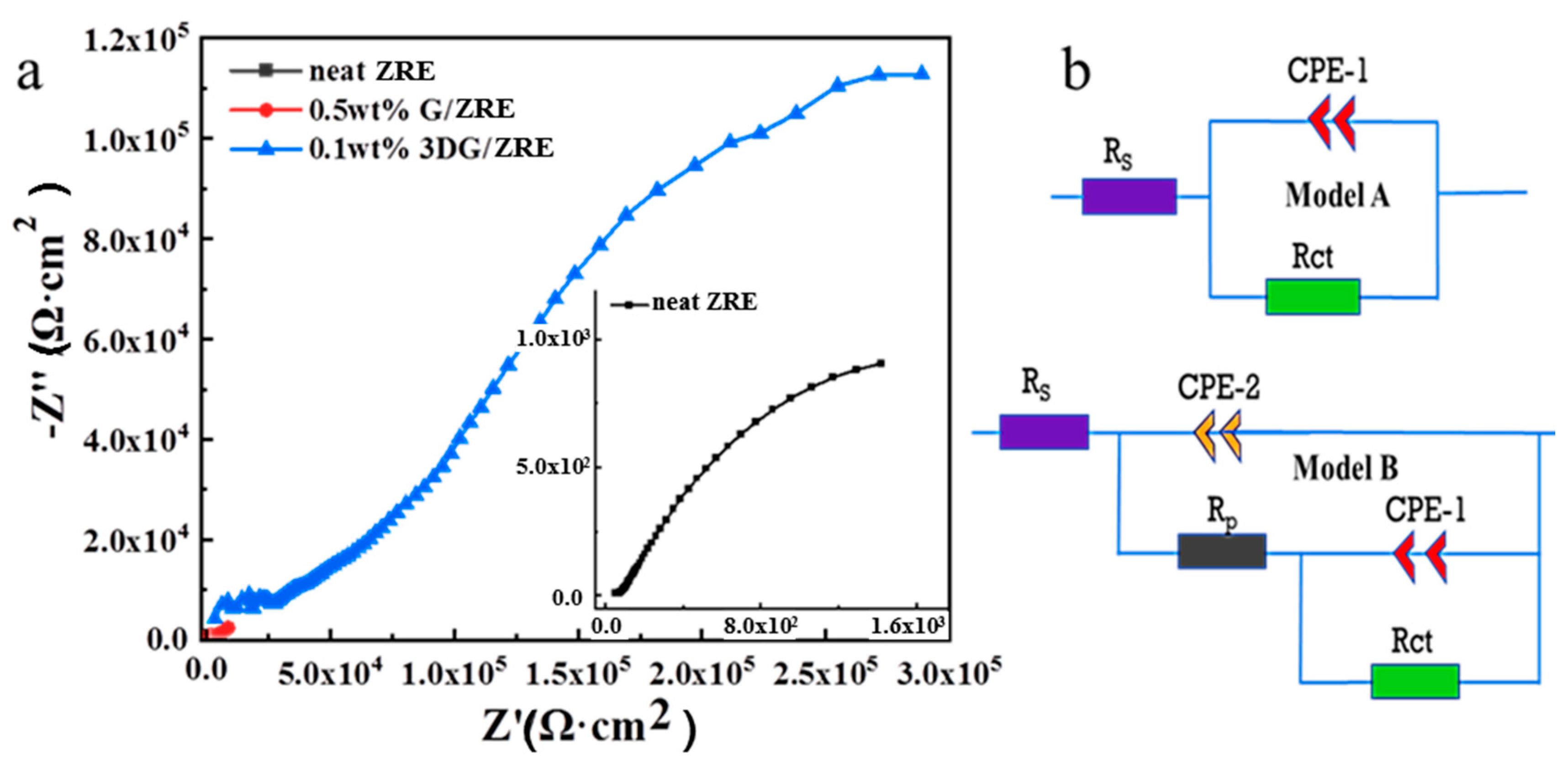
| ZRE Samples | CPE-1 (S·cm−2·sn) | Rp(Ω·cm2) | CPE-2 (S·cm−2·sn) | Rct (Ω·cm2) | Model |
|---|---|---|---|---|---|
| neat ZRE | 6.84 × 10⁻⁴ | - | - | 8.37 × 10³ | A |
| 0.5 wt% G/ZRE | 7.19 × 10⁻⁷ | 3.53 × 10³ | 1.03 × 10⁻⁴ | 1.29 × 10⁴ | B |
| 0.1 wt% 3DG/ZRE | 5.02 × 10⁻⁸ | 3.59 × 10⁴ | 1.23 × 10⁻⁵ | 5.99 × 10⁵ | B |
Disclaimer/Publisher’s Note: The statements, opinions and data contained in all publications are solely those of the individual author(s) and contributor(s) and not of MDPI and/or the editor(s). MDPI and/or the editor(s) disclaim responsibility for any injury to people or property resulting from any ideas, methods, instructions or products referred to in the content. |
© 2023 by the authors. Licensee MDPI, Basel, Switzerland. This article is an open access article distributed under the terms and conditions of the Creative Commons Attribution (CC BY) license (https://creativecommons.org/licenses/by/4.0/).
Share and Cite
Qin, Z.; Su, Y.; Bai, Y.; Lu, H.; Peng, T.; Zhong, H.; Chen, T.; Du, X. Improving the Corrosion Resistance of Zn-Rich Epoxy Coating with Three-Dimensional Porous Graphene. Polymers 2023, 15, 4302. https://doi.org/10.3390/polym15214302
Qin Z, Su Y, Bai Y, Lu H, Peng T, Zhong H, Chen T, Du X. Improving the Corrosion Resistance of Zn-Rich Epoxy Coating with Three-Dimensional Porous Graphene. Polymers. 2023; 15(21):4302. https://doi.org/10.3390/polym15214302
Chicago/Turabian StyleQin, Zhihong, Yinqiang Su, Yang Bai, Hangqi Lu, Tao Peng, Huifeng Zhong, Tao Chen, and Xusheng Du. 2023. "Improving the Corrosion Resistance of Zn-Rich Epoxy Coating with Three-Dimensional Porous Graphene" Polymers 15, no. 21: 4302. https://doi.org/10.3390/polym15214302
APA StyleQin, Z., Su, Y., Bai, Y., Lu, H., Peng, T., Zhong, H., Chen, T., & Du, X. (2023). Improving the Corrosion Resistance of Zn-Rich Epoxy Coating with Three-Dimensional Porous Graphene. Polymers, 15(21), 4302. https://doi.org/10.3390/polym15214302