
Three-Dimensional-Printed Fabrication of POFs Using Different Filaments and Their Characterization for Sensing Applications

 ,
,  , ,
, ,  and
and 
Abstract
:1. Introduction
2. Fabrication Method
3. Experimental Setup
3.1. Optical Fiber Characterization
3.1.1. Mechanical Characterization
3.1.2. Optical Characterization
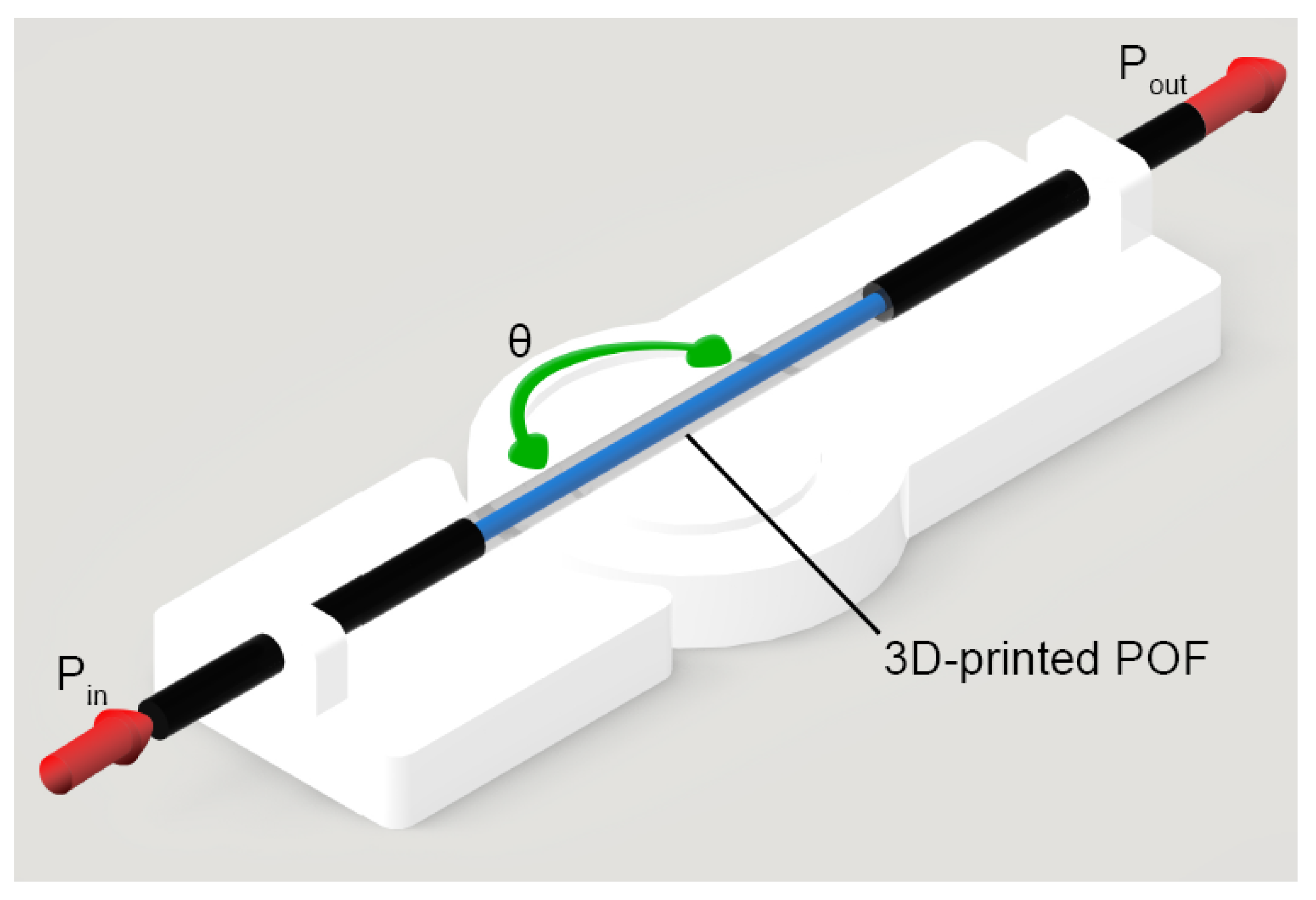
3.2. Intensity Variation-Based Sensors
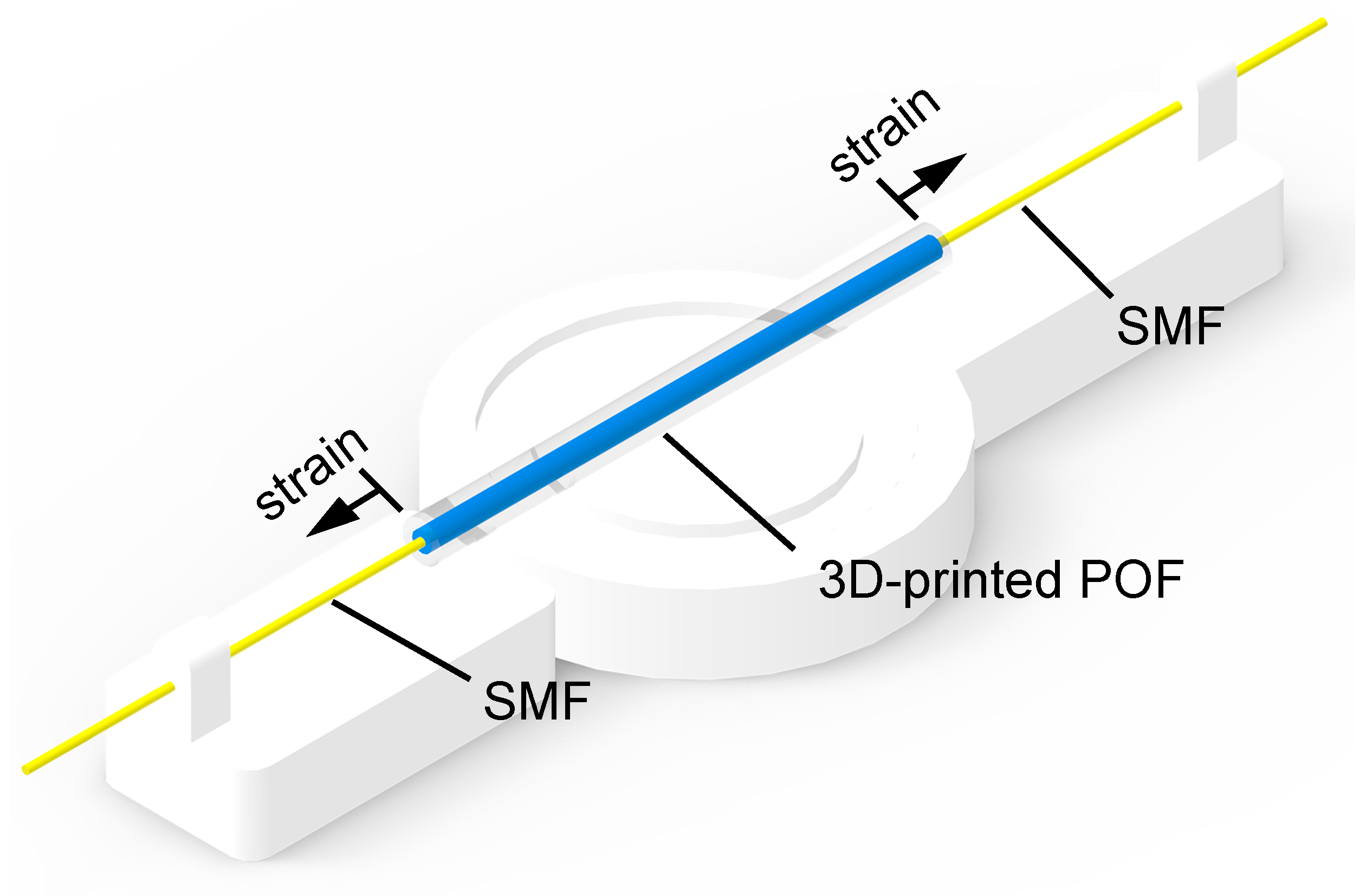
3.3. Modal Interferometer
4. Results and Discussion
4.1. POF Fabrication
4.2. POF Characterization
4.2.1. Optical Characterization
4.2.2. Mechanical Characterization
4.3. Curvature and Temperature Sensors Results
4.4. Interferometer Results
5. Conclusions
Author Contributions
Funding
Institutional Review Board Statement
Informed Consent Statement
Data Availability Statement
Conflicts of Interest
References
- Ziemann, O.; Krauser, J.; Zamzow, P.E.; Daum, W. POF Handbook; Springer: Berlin/Heidelberg, Germany, 2008. [Google Scholar]
- Ziemann, O.; Krauser, J.; Zamzow, P.E.; Daum, W. POF-Polymer Optical Fibers for Data Communication; Springer Science & Business Media: Berlin/Heidelberg, Germany, 2002. [Google Scholar]
- Prado, A.R.; Leal-Junior, A.G.; Marques, C.; Leite, S.; De Sena, G.L.; Machado, L.C.; Frizera, A.; Ribeiro, M.R.; Pontes, M.J. Polymethyl methacrylate recycling (PMMA) for the production of optical fiber sensor systems. Opt. Express 2017, 25, 30051–30060. [Google Scholar] [CrossRef] [PubMed]
- Canning, J.; Hossain, M.A.; Han, C.; Chartier, L.; Cook, K.; Athanaze, T. Drawing optical fibers from three-dimensional printers. Opt. Lett. 2016, 41, 5551–5554. [Google Scholar] [CrossRef] [PubMed]
- Moslan, M.S.; Othman, M.H.D.; Rahman, M.A.; Reza, A. Fabrication of polycarbonate-based polymer optical fiber cladding: Effect of different solvents. Malays. J. Fundam. Appl. Sci. 2019, 15, 795–798. [Google Scholar]
- Chen, Z.; Li, Z.; Li, J.; Liu, C.; Lao, C.; Fu, Y.; Liu, C.; Li, Y.; Wang, P.; He, Y. 3D printing of ceramics: A review. J. Eur. Ceram. Soc. 2019, 39, 661–687. [Google Scholar] [CrossRef]
- Beckers, M.; Schlüter, T.; Vad, T.; Gries, T.; Bunge, C.A. An overview on fabrication methods for polymer optical fibers. Polym. Int. 2015, 64, 25–36. [Google Scholar] [CrossRef]
- Hirose, R.; Asai, M.; Kondo, A.; Koike, Y. Preparation of graded-index plastic optical fiber by co-extrusion process. In Proceedings of the Organic Photonic Materials and Devices IX, San Jose, CA, USA, 20 January 2007; Volume 6470, pp. 120–129. [Google Scholar]
- Berry, S.M.; Harfenist, S.A.; Cohn, R.W.; Keynton, R.S. Characterization of micromanipulator-controlled dry spinning of micro-and sub-microscale polymer fibers. J. Micromech. Microeng. 2006, 16, 1825. [Google Scholar] [CrossRef] [Green Version]
- Beckers, M.; Schlüter, T.; Gries, T.; Seide, G.; Bunge, C.A. Fabrication techniques for polymer optical fibres. In Polymer Optical Fibres; Elsevier: Amsterdam, The Netherlands, 2017; pp. 187–199. [Google Scholar]
- Akrami, P.; Adamu, A.I.; Woyessa, G.; Rasmussen, H.K.; Bang, O.; Markos, C. High-temperature polymer multimaterial fibers. In Proceedings of the The European Conference on Lasers and Electro-Optics; Optical Society of America: Washington, DC, USA, 2021; p. ce_8_3. [Google Scholar]
- Tao, G.; Abouraddy, A.F.; Stolyarov, A.M.; Fink, Y. Multimaterial fibers. In Lab-on-Fiber Technology; Springer: Berlin/Heidelberg, Germany, 2015; pp. 1–26. [Google Scholar]
- Gibson, I.; Rosen, D.W.; Stucker, B.; Khorasani, M.; Rosen, D.; Stucker, B.; Khorasani, M. Additive Manufacturing Technologies; Springer: Berlin/Heidelberg, Germany, 2021; Volume 1. [Google Scholar]
- Ngo, T.D.; Kashani, A.; Imbalzano, G.; Nguyen, K.T.; Hui, D. Additive manufacturing (3D printing): A review of materials, methods, applications and challenges. Compos. Part B Eng. 2018, 143, 172–196. [Google Scholar] [CrossRef]
- Xie, R.; Weisen, A.R.; Lee, Y.; Aplan, M.A.; Fenton, A.M.; Masucci, A.E.; Kempe, F.; Sommer, M.; Pester, C.W.; Colby, R.H.; et al. Glass transition temperature from the chemical structure of conjugated polymers. Nat. Commun. 2020, 11, 893. [Google Scholar] [CrossRef] [Green Version]
- Mohamed, O.A.; Masood, S.H.; Bhowmik, J.L. Optimization of fused deposition modeling process parameters: A review of current research and future prospects. Adv. Manuf. 2015, 3, 42–53. [Google Scholar] [CrossRef]
- Chohan, J.S.; Singh, R.; Boparai, K.S.; Penna, R.; Fraternali, F. Dimensional accuracy analysis of coupled fused deposition modeling and vapour smoothing operations for biomedical applications. Compos. Part B Eng. 2017, 117, 138–149. [Google Scholar] [CrossRef]
- Shahrubudin, N.; Lee, T.C.; Ramlan, R. An overview on 3D printing technology: Technological, materials, and applications. Procedia Manuf. 2019, 35, 1286–1296. [Google Scholar] [CrossRef]
- Hsueh, M.H.; Lai, C.J.; Wang, S.H.; Zeng, Y.S.; Hsieh, C.H.; Pan, C.Y.; Huang, W.C. Effect of Printing Parameters on the Thermal and Mechanical Properties of 3D-Printed PLA and PETG, Using Fused Deposition Modeling. Polymers 2021, 13, 1758. [Google Scholar] [CrossRef] [PubMed]
- Valvez, S.; Silva, A.P.; Reis, P.N.B. Optimization of Printing Parameters to Maximize the Mechanical Properties of 3D-Printed PETG-Based Parts. Polymers 2022, 14, 2564. [Google Scholar] [CrossRef]
- Soleyman, E.; Aberoumand, M.; Rahmatabadi, D.; Soltanmohammadi, K.; Ghasemi, I.; Baniassadi, M.; Abrinia, K.; Baghani, M. Assessment of controllable shape transformation, potential applications, and tensile shape memory properties of 3D printed PETG. J. Mater. Res. Technol. 2022, 18, 4201–4215. [Google Scholar] [CrossRef]
- Kováčová, M.; Kozakovičová, J.; Procházka, M.; Janigová, I.; Vysopal, M.; Černičková, I.; Krajčovič, J.; Špitalský, Z. Novel Hybrid PETG Composites for 3D Printing. Appl. Sci. 2020, 10, 3062. [Google Scholar] [CrossRef]
- Soleyman, E.; Aberoumand, M.; Soltanmohammadi, K.; Rahmatabadi, D.; Ghasemi, I. 4D printing of PET-G via FDM including tailormade excess third shape. Manuf. Lett. 2022, 33, 1–4. [Google Scholar] [CrossRef]
- Soleyman, E.; Rahmatabadi, D.; Soltanmohammadi, K.; Aberoumand, M.; Ghasemi, I.; Abrinia, K.; Baniassadi, M.; Wang, K.; Baghani, M. Shape memory performance of PETG 4D printed parts under compression in cold, warm, and hot programming. Smart Mater. Struct. 2022, 31, 085002. [Google Scholar] [CrossRef]
- Prajzler, V.; Kulha, P.; Knietel, M.; Enser, H. Large core plastic planar optical splitter fabricated by 3D printing technology. Opt. Commun. 2017, 400, 38–42. [Google Scholar] [CrossRef]
- Inamura, C.; Stern, M.; Lizardo, D.; Houk, P.; Oxman, N. Additive Manufacturing of Transparent Glass Structures. 3D Print. Addit. Manuf. 2018, 5, 269–283. [Google Scholar] [CrossRef]
- Prajzler, V.; Zavřel, J. Large core optical elastomer splitter fabricated by using 3D printing pattern. Opt. Quantum Electron. 2021, 53, 337. [Google Scholar] [CrossRef]
- Luo, Y.; Canning, J.; Zhang, J.; Peng, G.D. Toward optical fibre fabrication using 3D printing technology. Opt. Fiber Technol. 2020, 58, 102299. [Google Scholar] [CrossRef]
- Leal-Junior, A.; Díaz, C.; Marques, C.; Frizera, A.; Pontes, M. 3D-printing techniques on the development of multiparameter sensors using one FBG. Sensors 2019, 19, 3514. [Google Scholar] [CrossRef] [PubMed] [Green Version]
- Leal-Junior, A.; Casas, J.; Marques, C.; Pontes, M.; Frizera, A. Application of Additive Layer Manufacturing Technique on the Development of High Sensitive Fiber Bragg Grating Temperature Sensors. Sensors 2018, 18, 4120. [Google Scholar] [CrossRef] [Green Version]
- Leal-Junior, A.G.; Marques, C.; Ribeiro, M.R.N.; Pontes, M.J.; Frizera, A. FBG-Embedded 3D Printed ABS Sensing Pads: The Impact of Infill Density on Sensitivity and Dynamic Range in Force Sensors. IEEE Sens. J. 2018, 18, 8381–8388. [Google Scholar] [CrossRef]
- Sun, D.; Chen, M.; Podilchak, S.; Georgiadis, A.; Abdullahi, Q.S.; Joshi, R.; Yasin, S.; Rooney, J.; Rooney, J. Investigating flexible textile-based coils for wireless charging wearable electronics. J. Ind. Text. 2020, 50, 333–345. [Google Scholar] [CrossRef]
- Abro, Z.A.; Hong, C.; Chen, N.; Zhang, Y.; Lakho, R.A.; Yasin, S. A fiber Bragg grating-based smart wearable belt for monitoring knee joint postures. Text. Res. J. 2020, 90, 386–394. [Google Scholar] [CrossRef]
- Avellar, L.; Stefano Filho, C.; Delgado, G.; Frizera, A.; Rocon, E.; Leal-Junior, A. AI-enabled photonic smart garment for movement analysis. Sci. Rep. 2022, 12, 4067. [Google Scholar] [CrossRef]
- Leal-Junior, A.; Macedo, L.; Frizera, A.; Pontes, M.J. Polymer Optical Fiber Multimaterial: Flexible and Customizable Approach in Sensors Development. IEEE Photonics Technol. Lett. 2022, 34, 611–614. [Google Scholar] [CrossRef]
- Alam, F.; Elsherif, M.; Salih, A.E.; Butt, H. 3D printed polymer composite optical fiber for sensing applications. Addit. Manuf. 2022, 58, 102996. [Google Scholar] [CrossRef]
- Cennamo, N.; Zeni, L. Polymer Optical Fibers for Sensing. Macromol. Symp. 2020, 389, 1900074. [Google Scholar] [CrossRef]
- Peters, K. Polymer optical fiber sensors—A review. Smart Mater. Struct. 2011, 20, 013002. [Google Scholar] [CrossRef]
- Sheng, C.; He, G.; Hu, Z.; Chou, C.; Shi, J.; Li, J.; Meng, Q.; Ning, X.; Wang, L.; Ning, F. Yarn on yarn abrasion failure mechanism of ultrahigh molecular weight polyethylene fiber. J. Eng. Fibers Fabr. 2021, 16, 15589250211052766. [Google Scholar] [CrossRef]
- Aberoumand, M.; Soltanmohammadi, K.; Soleyman, E.; Rahmatabadi, D.; Ghasemi, I.; Baniassadi, M.; Abrinia, K.; Baghani, M. A comprehensive experimental investigation on 4D printing of PET-G under bending. J. Mater. Res. Technol. 2022, 18, 2552–2569. [Google Scholar] [CrossRef]
- ISO. Plastics—Determination of Tensile Properties—Part 1: General Principles; ISO 527-1:2012; ISO: Geneva, Switzerland, 2012; Available online: https://www.iso.org/standard/56045.html (accessed on 29 November 2022).
- Ding, M.; Fan, D.; Wang, W.; Luo, Y.; Peng, G.D. Basics of optical fiber measurements. In Handbook of Optical Fibers; Springer: Berlin/Heidelberg, Germany, 2019; pp. 1099–1137. [Google Scholar]
- Macedo, L.; Junior, R.W.M.P.; Frizera, A.; Pontes, M.J.; Leal-Junior, A. An alternative to discarded plastic: A report of polymer optical fiber made from recycled materials for the development of biosensors. Opt. Fiber Technol. 2022, 72, 103001. [Google Scholar] [CrossRef]
- Broadway, C.F.B.; Kalli, K.; Theodosiou, A.; Zubel, M.; Sugden, K.; Mégret, P.; Caucheteur, C. L-band CYTOP Bragg gratings for ultrasound sensing. In Proceedings of the Micro-Structured and Specialty Optical Fibres V; Bunge, C.A., Kalli, K., Mendez, A., Eds.; SPIE: Strasbourg, France, 2018; Volume 10681, p. 8. [Google Scholar] [CrossRef]
- Zhao, Q.; Tian, F.; Yang, X.; Li, S.; Zhang, J.; Zhu, X.; Yang, J.; Liu, Z.; Zhang, Y.; Yuan, T.; et al. Optical fibers with special shaped cores drawn from 3D printed preforms. Optik 2017, 133, 60–65. [Google Scholar] [CrossRef]
- Hsu, Y.; Wang, L.; Liu, W.F.; Chiang, Y. Temperature compensation of optical fiber Bragg grating pressure sensor. IEEE Photonics Technol. Lett. 2006, 18, 874–876. [Google Scholar] [CrossRef]
- Jin, L.; Zhang, W.; Zhang, H.; Liu, B.; Zhao, J.; Tu, Q.; Kai, G.; Dong, X. An embedded FBG sensor for simultaneous measurement of stress and temperature. IEEE Photonics Technol. Lett. 2005, 18, 154–156. [Google Scholar] [CrossRef]


| Sample | Solution | Time (s) | Refractive Index |
|---|---|---|---|
| 1 | Methyl acetate | 6 | 1.361 |
| 2 | Methyl acetate | 60 | 1.361 |
| 3 | Methyl acetate | 600 | 1.361 |
| 4 | Sodium fluoride | 6 | 1.325 |
| 5 | Sodium fluoride | 60 | 1.325 |
| 6 | Sodium fluoride | 600 | 1.325 |
| 7 | Dimethylformamide | 6 | 1.4305 |
| 8 | Dimethylformamide | 60 | 1.4305 |
| 9 | Dimethylformamide | 600 | 1.4305 |
| Sample | Core Diameter (mm) | Cladding | Average Diameter (mm) | Standard Deviation (mm) |
|---|---|---|---|---|
| 1 | 0.2 | Optical Adhesive | 0.83 | 0.02 |
| 2 | 0.4 | Optical Adhesive | 0.84 | 0.03 |
| 3 | 0.2 | Sodium fluoride 6 s | 0.20 | 0.01 |
| 4 | 0.2 | Sodium fluoride 60 s | 0.19 | 0.01 |
| 5 | 0.2 | Sodium fluoride 600 s | 0.20 | 0.02 |
| 6 | 0.4 | Methyl acetate 6 s | 0.42 | 0.02 |
| 7 | 0.4 | Methyl acetate 60 s | 0.39 | 0.03 |
| 8 | 0.4 | Sodium fluoride 6 s | 0.44 | 0.00 |
| 9 | 0.4 | Sodium fluoride 60 s | 0.45 | 0.01 |
| 10 | 0.4 | Sodium fluoride 600 s | 0.44 | 0.02 |
| Material | Refractive Index |
|---|---|
| HDglass | 1.645 |
| PET-G | 1.655 |
| PLA | 1.648 |
| Tritan | 1.646 |
| Optical Adhesive | 1.56 |
| Diameter (mm) | L1 (mm) | P1 (mW) | L2 (mm) | P2 (mW) | Attenuation (dB/cm) |
|---|---|---|---|---|---|
| 0.2 | 69.60 | 0.05 | 60.67 | 1.11 | 3.62 |
| 0.4 | 66.00 | 2.97 | 56.86 | 3.00 | 0.05 |
| Sample | L1 (mm) | P1 (mW) | L2 (mm) | P2 (mW) | Attenuation (dB/cm) |
|---|---|---|---|---|---|
| 1 | 30.68 | 0.52 | 25.13 | 0.58 | 1.23 |
| 2 | 49.00 | 2.99 | 39.67 | 2.98 | 0.02 |
| 6 | 40.00 | 3.00 | 35.11 | 2.99 | 0.03 |
| 7 | 54.30 | 2.12 | 49.11 | 3.00 | 2.94 |
| 8 | 55.00 | 3.00 | 48.21 | 2.99 | 0.03 |
| 9 | 63.50 | 0.45 | 57.20 | 2.65 | 12.33 |
| 10 | 47.40 | 3.00 | 41.22 | 2.99 | 0.10 |
| Property | HDglass | Tritan | PET-G | PLA |
|---|---|---|---|---|
| E (GPa) | 1.6 | 1.3 | 1.7 | 2.4 |
| (%) | 1.2 | 2.5 | 1.0 | 0.8 |
| Ultimate strength (MPa) | 50 | 53 | 33 | 31 |
Disclaimer/Publisher’s Note: The statements, opinions and data contained in all publications are solely those of the individual author(s) and contributor(s) and not of MDPI and/or the editor(s). MDPI and/or the editor(s) disclaim responsibility for any injury to people or property resulting from any ideas, methods, instructions or products referred to in the content. |
© 2023 by the authors. Licensee MDPI, Basel, Switzerland. This article is an open access article distributed under the terms and conditions of the Creative Commons Attribution (CC BY) license (https://creativecommons.org/licenses/by/4.0/).
Share and Cite
Pires-Junior, R.; Macedo, L.; Frizera, A.; Pontes, M.J.; Leal-Junior, A. Three-Dimensional-Printed Fabrication of POFs Using Different Filaments and Their Characterization for Sensing Applications. Polymers 2023, 15, 640. https://doi.org/10.3390/polym15030640
Pires-Junior R, Macedo L, Frizera A, Pontes MJ, Leal-Junior A. Three-Dimensional-Printed Fabrication of POFs Using Different Filaments and Their Characterization for Sensing Applications. Polymers. 2023; 15(3):640. https://doi.org/10.3390/polym15030640
Chicago/Turabian StylePires-Junior, Robertson, Leandro Macedo, Anselmo Frizera, Maria José Pontes, and Arnaldo Leal-Junior. 2023. "Three-Dimensional-Printed Fabrication of POFs Using Different Filaments and Their Characterization for Sensing Applications" Polymers 15, no. 3: 640. https://doi.org/10.3390/polym15030640
APA StylePires-Junior, R., Macedo, L., Frizera, A., Pontes, M. J., & Leal-Junior, A. (2023). Three-Dimensional-Printed Fabrication of POFs Using Different Filaments and Their Characterization for Sensing Applications. Polymers, 15(3), 640. https://doi.org/10.3390/polym15030640