
Sustainable Multi-Network Cationic Cryogels for High-Efficiency Removal of Hazardous Oxyanions from Aqueous Solutions


Abstract
:1. Introduction
2. Materials and Methods
2.1. Materials
2.2. Preparation of Cationic Composite Cryogels
2.3. Characterization of Cationic Composite Cryogels
2.4. Sorption of Oxyanions
3. Results
3.1. Synthesis and Characterization of Multi-Network Cationic Composite Cryogels
3.1.1. Synthesis
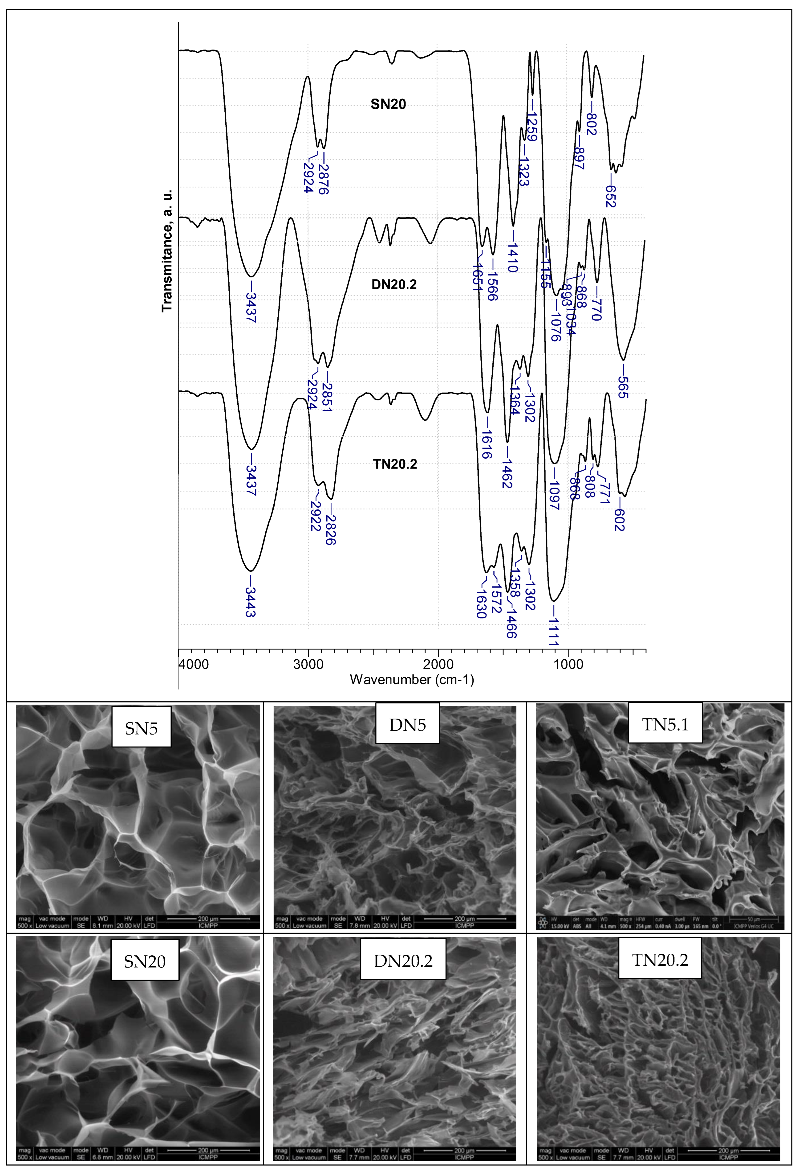
3.1.2. Characterization
3.2. Sorption Performances
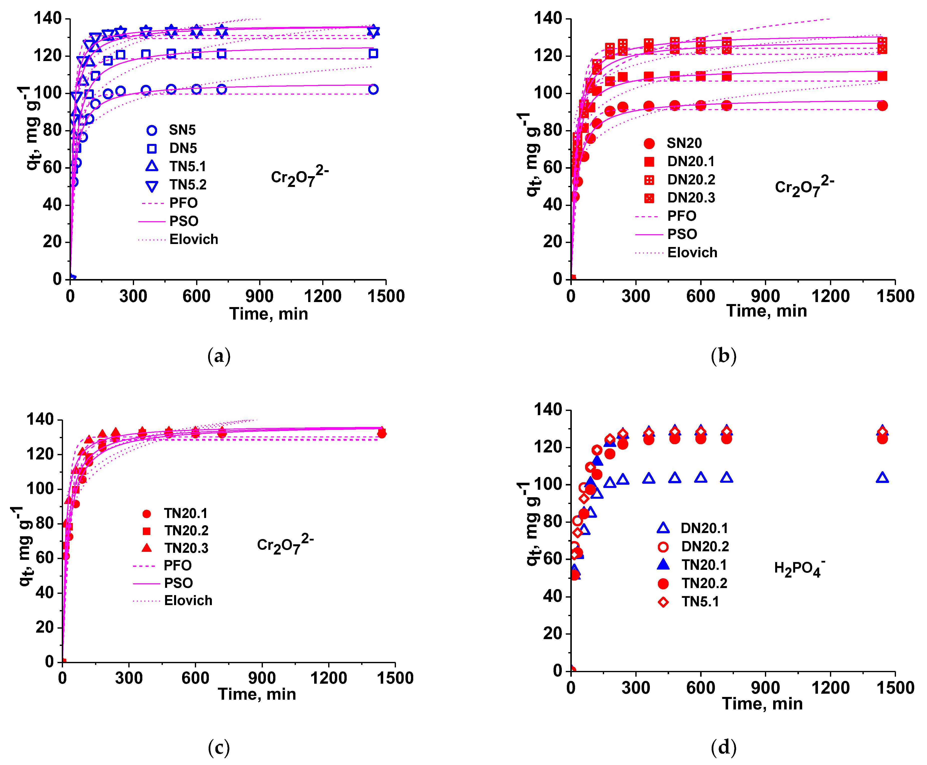
3.2.1. Sorption Kinetics
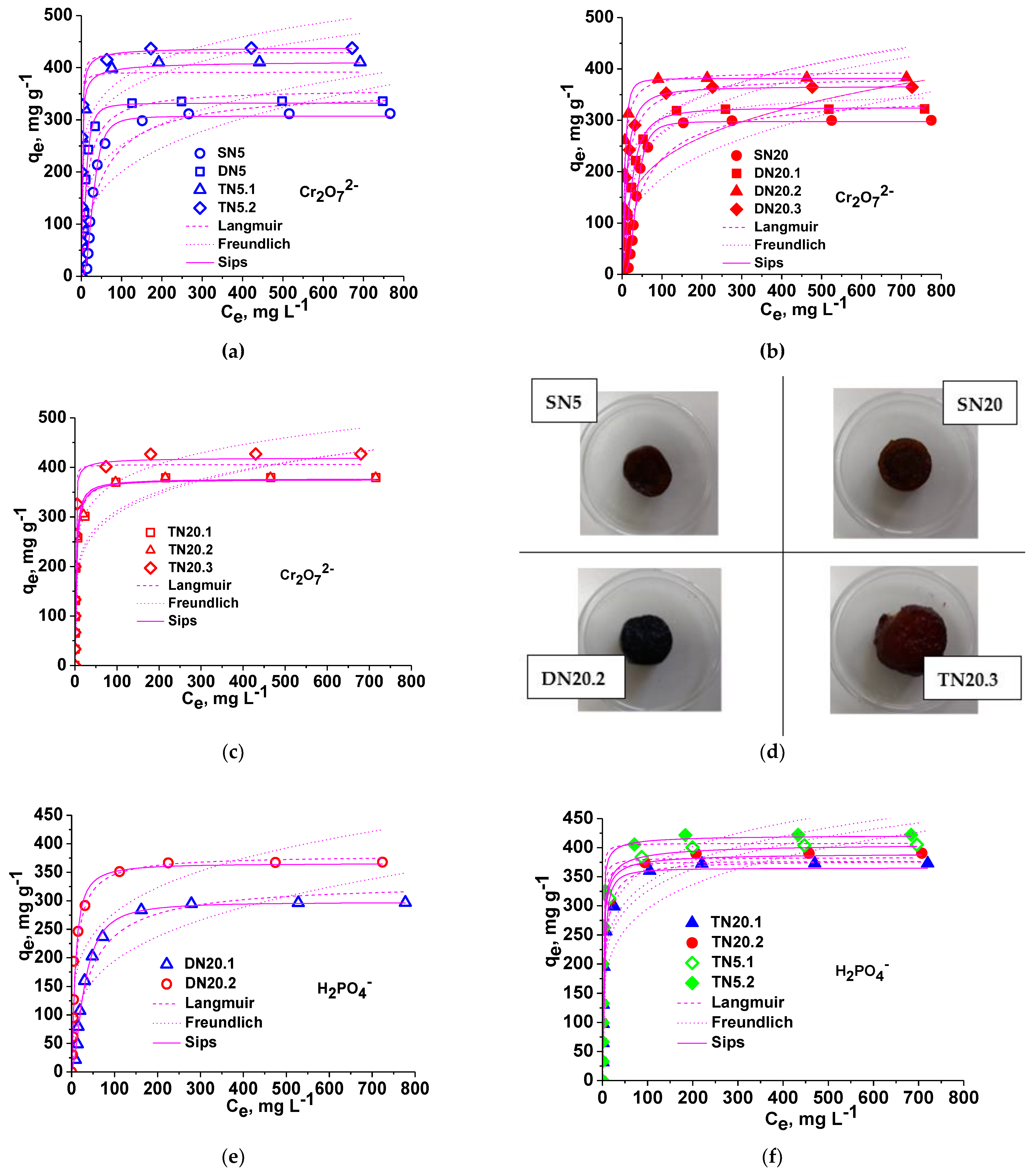
3.2.2. Isotherms
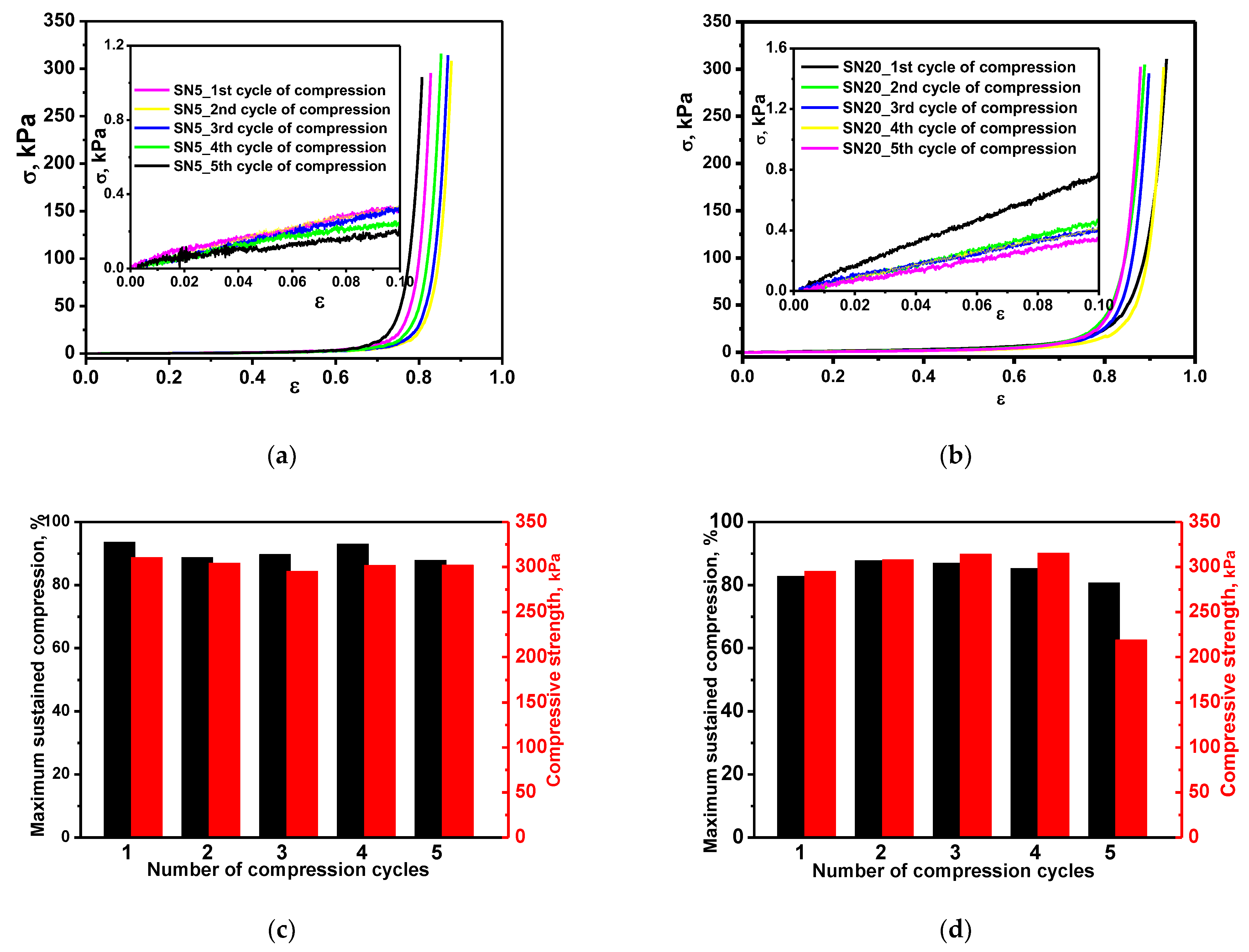
3.2.3. Reusability
4. Conclusions
Supplementary Materials
Author Contributions
Funding
Institutional Review Board Statement
Data Availability Statement
Conflicts of Interest
References
- Bucatariu, F.; Teodosiu, C.; Morosanu, I.; Fighir, D.; Ciobanu, R.; Petrila, L.M.; Mihai, M. An overview on composite sorbents based on polyelectrolytes used in advanced wastewater treatment. Polymers 2021, 13, 3963. [Google Scholar] [CrossRef] [PubMed]
- Rahman, M.L.; Fui, C.J.; Ting, T.X.; Sarjadi, M.S.; Arshad, S.E.; Musta, B. Polymer ligands derived from iute fiber for heavy metal removal from electroplating wastewater. Polymers 2020, 12, 2521. [Google Scholar] [CrossRef]
- Zaharia, M.M.; Bucatariu, F.; Vasiliu, A.L.; Mihai, M. Stable and reusable acrylic ion exchangers. From HMIs highly polluted tailing pond to safe and clean water. Chemosphere 2022, 304, 185383. [Google Scholar] [CrossRef]
- Iqbal, S.; Javed, M.; Bahadur, A.; Qamar, M.A.; Ahmad, M.; Shoaib, M.; Raheel, M.; Ahmad, N.; Akbar, M.B.; Li, H. Controlled synthesis of Ag-doped CuO nanoparticles as a core with poly(acrylic acid) microgel shell for efficient removal of methylene blue under visible light. J. Mater. Sci. Mater. Electron. 2020, 31, 8423–8435. [Google Scholar] [CrossRef]
- Kuang, C.; Tan, P.; Bahadur, A.; Iqbal, S.; Javed, M.; Qamar, M.A.; Fayyaz, M.; Liu, G.; Alzahrani, O.M.; Alzahrani, E.; et al. Dye degradation study by incorporating Cu-doped ZnO photocatalyst into polyacrylamide microgel. J. Mater. Sci. Mater. Electron. 2022, 33, 9930–9940. [Google Scholar] [CrossRef]
- Pakade, V.E.; Tavengwa, N.T.; Madikizela, L.M. Recent advances in hexavalent chromium removal from aqueous solutions by adsorptive methods. RSC Adv. 2019, 9, 26142–26164. [Google Scholar] [CrossRef]
- Ghiorghita, C.A.; Dinu, M.V.; Lazar, M.M.; Dragan, E.S. Polysaccharide-based composite hydrogels as sustainable materials for removal of pollutants from wastewaters. Molecules 2022, 27, 8574. [Google Scholar] [CrossRef] [PubMed]
- Pehlivan, E.; Cetin, S. Sorption of Cr(VI) ions on two Lewatit-anion exchange resins and their quantitative determination using UV-visible spectrophotometer. J. Hazard. Mater. 2009, 163, 448–453. [Google Scholar] [CrossRef] [PubMed]
- Markovic, B.M.; Stefanovic, I.S.; Hercigonja, R.V.; Pergal, M.V.; Markovic, J.P.; Onjia, A.E.; Nastasovic, A.B. Novel hexamethylene diamine-functionalized macroporous copolymer for chromium removal from aqueous solutions. Polym. Int. 2017, 66, 679–689. [Google Scholar] [CrossRef]
- Zang, Y.; Yue, Q.; Kan, Y.; Zhang, L.; Gao, B. Research on adsorption of Cr(VI) by poly-epichlorohydrin-dimethylamine (EPIDMA) modified weakly basic anion exchange resin D301. Ecotoxicol. Environ. Saf. 2018, 161, 467–473. [Google Scholar] [CrossRef]
- Korak, J.A.; Huggins, R.; Arias-Paic, M. Regeneration of pilot-scale ion exchange columns for hexavalent chromium removal. Water Res. 2017, 118, 141–151. [Google Scholar] [CrossRef]
- Wang, X.; Wu, C.; Tian, L.; Li, G.; Zhang, X.; Lei, F.; Qu, J.; Liu, P. Cationic polymer chain tethered on the pore-wall of 3-D ordered macroporous resin for the removal of hexavalent chromium from aqueous solution. React. Funct. Polym. 2015, 95, 55–61. [Google Scholar] [CrossRef]
- Hayashi, N.; Chen, J.; Seko, N. Nitrogen-containing fabric adsorbents prepared by radiation grafting for removal of chromium from wastewater. Polymers 2018, 10, 744. [Google Scholar] [CrossRef] [PubMed]
- Dragan, E.S.; Humelnicu, D.; Dinu, M.V.; Romeo Iulian Olariu, R.I. Kinetics, equilibrium modeling, and thermodynamics on removal of Cr(VI) ions from aqueous solution using novel composites with strong base anion exchanger microspheres embedded into chitosan/poly(vinyl amine) cryogels. Chem. Eng. J. 2017, 330, 675–691. [Google Scholar] [CrossRef]
- Li, K.; Li, P.; Cai, J.; Xiao, S.; Yang, H.; Li, A. Efficient adsorption of both methyl orange and chromium from their aqueous mixtures using a quaternary ammonium salt modified chitosan magnetic composite adsorbent. Chemosphere 2016, 154, 310–318. [Google Scholar] [CrossRef]
- Khalil, T.E.; Elhusseiny, A.F.; El-dissouky, A.; Ibrahim, N.M. Functionalized chitosan nanocomposites for removal of toxic Cr (VI) from aqueous solution. React. Funct. Polym. 2020, 146, 104407. [Google Scholar] [CrossRef]
- Du, M.; Zhang, Y.; Wang, Z.; Lv, M.; Tang, A.; Yu, Y.; Qu, X.; Chen, Z.; Wen, Q.; Li, A. Insight into the synthesis and adsorption mechanism of adsorbents for efficient phosphate removal: Exploration from synthesis to modification. Chem. Eng. J. 2022, 442, 136147. [Google Scholar] [CrossRef]
- Shen, Z.; Dong, X.; Shi, J.; Ma, Y.; Liu, D.; Fan, J. Simultaneous removal of nitrate/phosphate with bimetallic nanoparticles of Fe coupled with copper or nickel supported on chelating resin. Environ. Sci. Pollut. Res. 2019, 26, 16568–16576. [Google Scholar] [CrossRef]
- Bui, T.H.; Hong, S.P.; Yoon, J. Development of nanoscale zirconium molybdate embedded anion exchange resin for selective removal of phosphate. Water Res. 2018, 134, 22–31. [Google Scholar] [CrossRef]
- Wiriyathamcharoen, S.; Sarkar, S.; Jiemvarangkul, P.; Nguyen, T.T.; Klysubun, W.; Padungthon, S. Synthesis optimization of hybrid anion exchanger containing triethylamine functional groups and hydrated Fe(III) oxide nanoparticles for simultaneous nitrate and phosphate removal. Chem. Eng. J. 2020, 381, 122671. [Google Scholar] [CrossRef]
- Du, J.; Dong, Z.; Yang, X.; Zhao, L. Radiation grafting of dimethylaminoethyl methacrylate on cotton linter and subsequent quaternization as new eco-friendly adsorbent for phosphate removal. Environ. Sci. Pollut. Res. 2020, 27, 24558–24567. [Google Scholar] [CrossRef] [PubMed]
- Wan, J.; Zhu, C.; Hu, J.; Zhang, T.C.; Richter-Egger, D.; Feng, X.; Zhou, A.; Tao, T. Zirconium-loaded magnetic interpenetrating network chitosan/poly(vinyl alcohol) hydrogels for phosphorus recovery from the aquatic environment. Appl. Surf. Sci. 2017, 423, 484–491. [Google Scholar] [CrossRef]
- Wang, J.; Wei, J. Facile synthesis of Zr(IV) crosslinked carboxymethyl cellulose/carboxymethyl chitosan hydrogel using PEG as pore-forming agent for enhanced phosphate removal. Int. J. Biol. Macromol. 2021, 176, 558–566. [Google Scholar] [CrossRef] [PubMed]
- Luo, H.; Zeng, X.; Liao, P.; Rong, H.; Zhang, T.C.; Zhang, Z.J.; Meng, X. Phosphorus removal and recovery from water with macroporous bead adsorbent constituted of alginate-Zr4+ and PNIPAM-interpenetrated networks. Int. J. Biol. Macromol. 2019, 126, 1133–1144. [Google Scholar] [CrossRef] [PubMed]
- Zhang, B.; Chen, N.; Feng, C.; Zhang, Z. Adsorption for phosphate by crosslinked/non-crosslinked-chitosan-Fe(III) complex sorbents: Characteristic and mechanism. Chem. Eng. J. 2018, 353, 361–372. [Google Scholar] [CrossRef]
- Zeng, H.; Sun, S.; Xu, K.; Zhao, W.; Hao, R.; Zhang, J.; Li, D. Iron-loaded magnetic alginate-chitosan double-gel interpenetrated porous beads for phosphate removal from water: Preparation, adsorption behavior and pH stability. React. Funct. Polym. 2022, 177, 105328. [Google Scholar] [CrossRef]
- Jia, Z.; Zeng, W.; Xu, H.; Li, S.; Peng, Y. Adsorption removal and reuse of phosphate from wastewater using a novel adsorbent of lanthanum-modified platanus biochar. Process Saf. Environ. Prot. 2020, 140, 221–232. [Google Scholar] [CrossRef]
- Liu, B.; Yu, Y.; Han, Q.; Lou, S.; Zhang, L.; Zhang, W. Fast and efficient phosphate removal on lanthanum-chitosan composite synthesized by controlling the amount of cross-linking agent. Int. J. Biol. Macromol. 2020, 157, 247–258. [Google Scholar] [CrossRef]
- Yang, Z.; Hou, J.; Pan, Z.; Wu, M.; Zhang, M.; Yin, X.; Wu, J.; Miao, L.; Liu, Q. A novel La(OH)3 decorated co-graft tannin and polyethyleneimine co-coating magnetic adsorbent for effective and selective phosphate removal from natural water and real wastewater. J. Clean. Prod. 2022, 369, 133345. [Google Scholar] [CrossRef]
- Malakhova, I.; Privar, Y.; Parotkina, Y.; Eliseikina, M.; Golikov, A.; Skatova, A.; Bratskaya, S. Supermacroporous monoliths based on polyethyleneimine: Fabrication and sorption properties under static and dynamic conditions. J. Environ. Chem. Eng. 2020, 8, 104395. [Google Scholar] [CrossRef]
- Huang, H.; Ren, D.; Qu, J. pH and temperature-responsive POSS-based poly(2-(dimethylamino) ethyl methacrylate) for highly efficient Cr(VI) adsorption. Colloid Polym. Sci. 2020, 298, 1515–1521. [Google Scholar] [CrossRef]
- Dragan, E.S. Advances in interpenetrating polymer network hydrogels and their applications. Pure Appl. Chem. 2014, 86, 1707–1721. [Google Scholar] [CrossRef]
- Dragan, E.S.; Humelnicu, D.; Dinu, M.V. Development of chitosan-poly(ethyleneimine) based double network cryogels and their application as superadsorbents for phosphate. Carbohydr. Polym. 2019, 210, 17–25. [Google Scholar] [CrossRef] [PubMed]
- Dragan, E.S.; Humelnicu, D.; Dinu, M.V. Designing smart triple-network cationic cryogels with outstanding efficiency and selectivity for deep cleaning of phosphate. Chem. Eng. J. 2021, 426, 131411. [Google Scholar] [CrossRef]
- Sedlačik, T.; Nanoyama, T.; Guo, H.; Kiyama, R.; Nakajima, T.; Takeda, Y.; Kurokawa, T.; Gong, J.P. Preparation of tough double and triple network supermacroporous hydrogels through repeated cryogelation. Chem. Mater. 2020, 32, 8576–8586. [Google Scholar] [CrossRef]
- Zou, W.; Chen, Y.; Zhang, X.; Li, J.; Sun, L.; Gui, Z.; Du, B.; Chen, S. Cytocompatibility chitosan based multi-network hydrogels with antimicrobial, cell anti-adhesive and mechanical properties. Carbohydr. Polym. 2018, 202, 246–257. [Google Scholar] [CrossRef]
- Yu, F.; Yang, P.; Yang, Z.; Zhang, X.; Ma, J. Double-network hydrogel adsorbents for environmental applications. Chem. Eng. J. 2021, 426, 131900. [Google Scholar] [CrossRef]
- Li, L.; Wu, P.; Yu, F.; Ma, J. Double network hydrogels for energy/environmental applications: Challenges and opportunities. J. Mater. Chem. A 2022, 10, 9215–9247. [Google Scholar] [CrossRef]
- Bercea, M. Bioinspired hydrogels as platforms for life-science applications: Challenges and opportunities. Polymers 2022, 14, 2365. [Google Scholar] [CrossRef]
- Gamzazade, A.I.; Shimac, V.M.; Skljar, A.M.; Stykova, E.V.; Pavlova, S.A.; Rogozin, S. Investigation of the hydrodynamic properties of chitosan solutions. Acta Polym. 1985, 36, 420–424. [Google Scholar] [CrossRef]
- Venkataraman, R.; Das, G.; Singh, S.R.; Pathak, L.C.; Ghosh, R.N.; Venkataraman, B.; Krishnamurthy, R. Study on influence of porosity, pore size, spatial and topological distribution of pores on microhardness of plasma sprayed ceramic coatings. Mater. Sci. Eng. A 2007, 445–446, 269–274. [Google Scholar] [CrossRef]
- Qi, X.; Chen, M.; Qian, Y.; Liu, M.; Li, Z.; Shen, L.; Qin, T.; Zhao, S.; Zeng, Q.; Shen, J. Construction of macroporous salecan polysaccharide-based adsorbents for wastewater remediation. Int. J. Biol. Macromol. 2019, 132, 429–438. [Google Scholar] [CrossRef]
- Ding, N.; Cai, X.; Zhang, P.; Dong, S.; Du, B.; Nie, J.; Yu, P. Mimicking the Mechanical Properties of Cartilage Using Ionic- and Hydrogen-Bond Cross-Linked Hydrogels with a High Equilibrium Water Content above 70%. ACS Appl. Polym. Mater. 2021, 3, 2709–2721. [Google Scholar] [CrossRef]
- Hu, X.; Wang, Y.; Zhang, L.; Xu, M. Design of a novel polysaccharide-based cryogel using triallyl cyanurate as crosslinker for cell adhesion and proliferation. Int. J. Biol. Macromol. 2019, 126, 221–228. [Google Scholar] [CrossRef] [PubMed]
- Dragan, E.S.; Dinu, M.V.; Ghiorghita, C.A. Chitosan-based polyelectrolyte complex cryogels with elasticity, toughness and delivery of curcumin engineered by polyions pair and cryostructuration steps. Gels 2022, 8, 240. [Google Scholar] [CrossRef] [PubMed]
- Dragan, E.S.; Ghiorghita, C.A.; Dinu, M.V.; Duceac, I.A.; Coseri, S. Fabrication of self-antibacterial chitosan/oxidized starch polyelectrolyte complex sponges for controlled delivery of curcumin. Food Hydrocolloids 2023, 135, 108147. [Google Scholar] [CrossRef]
- Duranoglu, D.; Trochimczuk, A.W.; Beker, U. Kinetics and thermodynamics of hexavalent chromium adsorption onto activated carbon derived from acrylonitrile-divinylbenzene copolymer. Chem. Eng. J. 2012, 187, 193–202. [Google Scholar] [CrossRef]
- Nagul, E.A.; McKelvie, I.D.; Worsfold, P.; Kolev, S.D. The molybdenum blue reaction for the determination of orthophosphate revisited: Opening the black box. Anal. Chim. Acta 2015, 890, 60–82. [Google Scholar] [CrossRef]
- Yuan, Q.; Shah, J.; Hein, S.; Misra, R.D.K. Controlled and extended drug release behavior of chitosan-based nanoparticle carrier. Acta Biomater. 2010, 6, 1140–1148. [Google Scholar] [CrossRef]
- Zhang, J.; Chen, N.; Tang, Z.; Yu, Y.; Hu, Q.; Feng, C. Adsorption of fluoride from aqueous solutions onto Fe-impregnated chitosan and mechanism study. Phys. Chem. Chem. Phys. 2015, 17, 12041. [Google Scholar] [CrossRef]
- Coates, J. Interpretation of Infrared Spectra. A practical approach. In Encyclopedia of Analytical Chemistry; Meyers, R.A., Ed.; John Wiley & Sons Ltd.: Chichester, UK, 2000; pp. 10815–10837. [Google Scholar]
- Wei, W.; Hu, X.; Qi, X.; Yu, H.; Liu, Y.; Li, J.; Zhang, J.; Dong, W. A novel thermo-responsive hydrogel based on salecan and poly(N-isopropylacrylamide): Synthesis and characterization. Colloids Surf. B Biointerfaces 2015, 125, 1–11. [Google Scholar] [CrossRef] [PubMed]
- Hu, X.; Feng, L.; Xie, A.; Wei, W.; Wang, S.; Zhang, J.; Dong, W. Synthesis and characterization of a novel hydrogel: Salecan/polyacrylamide semi-IPN hydrogel with a desirable pore structure. J. Mater. Chem. B 2014, 2, 3646–3658. [Google Scholar] [CrossRef] [PubMed]


| Cryogel Name | 1st Network | 2nd Network | 3rd Network | |||
|---|---|---|---|---|---|---|
| Name * | GA, Mole % | Name | Conc. wt.% | Name | Conc. wt.% | |
| SN5 | CS | 5 | - | - | - | - |
| DN5 | CS | 5 | PEI18 | 15 | - | - |
| TN5.1 | CS | 5 | PEI18 | 15 | PEI18 | 10 |
| TN5.2 | CS | 5 | PEI18 | 15 | PDMAEMA | 10 |
| SN20 | CS | 20 | - | - | - | - |
| DN20.1 | CS | 20 | PDMAEMA | 10 | - | - |
| DN20.2 | CS | 20 | PEI25 | 15 | - | - |
| DN20.3 | CS | 20 | PEI18 | 15 | - | - |
| TN20.1 | CS | 20 | PDMAEMA | 10 | PEI18 | 10 |
| TN20.2 | CS | 20 | PEI25 | 15 | PEI18 | 10 |
| TN20.3 | CS | 20 | PEI18 | 15 | PEI18 | 10 |
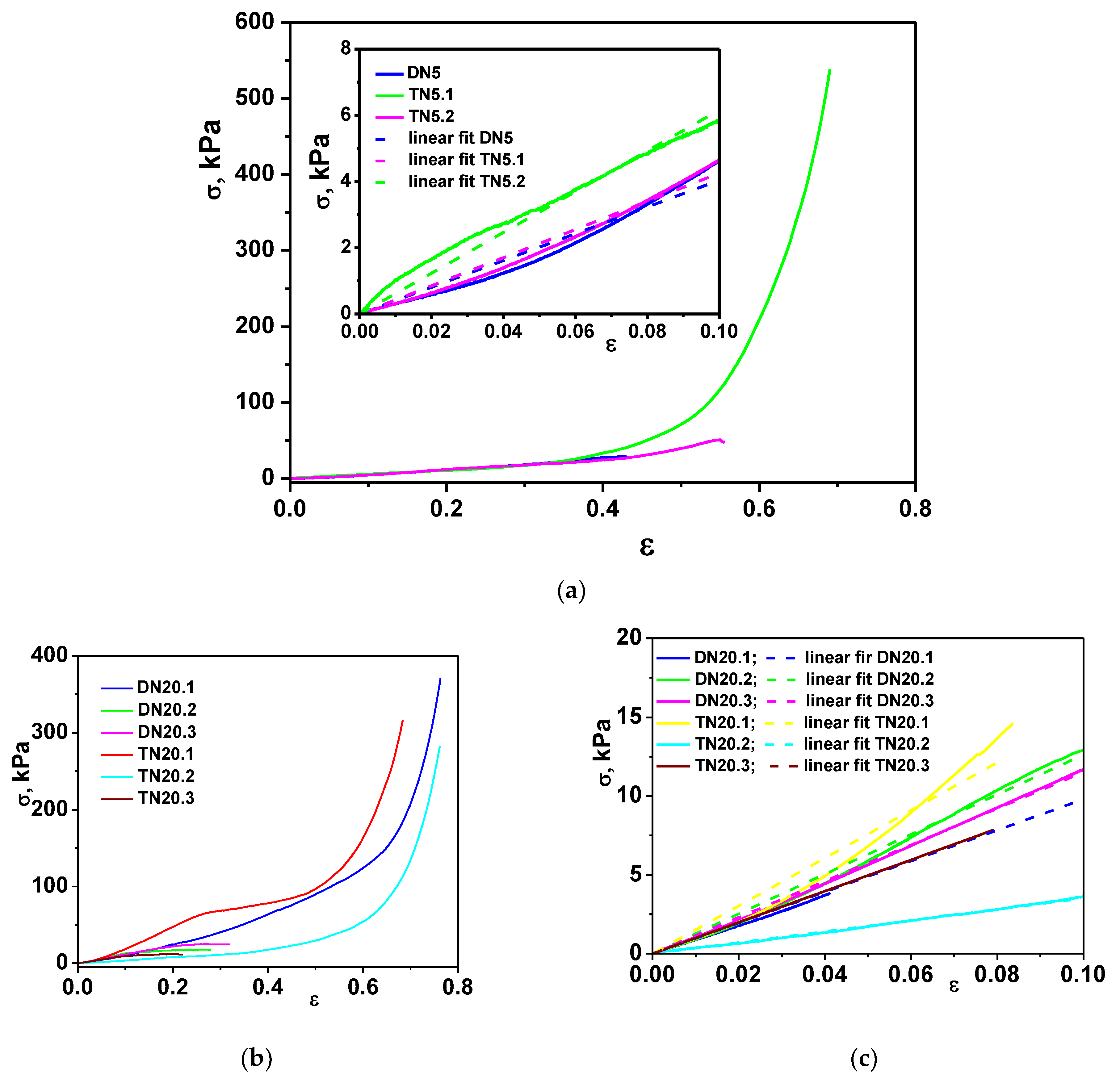
| Sample Code | Compressive Elastic Modulus, kPa | R2 | Compressive Nominal Stress, kPa | Strain% |
|---|---|---|---|---|
| DN5 | 40.37 | 0.985 | 31.38 | 52.90 |
| TN5.1 | 61.57 | 0.995 | 538.20 | 69.02 |
| TN5.2 | 42.51 | 0.991 | 48.07 | 55.63 |
| DN20.1 | 98.01 | 0.998 | 370.49 | 76.30 |
| DN20.2 | 126.26 | 0.997 | 14.45 | 13.30 |
| DN20.3 | 115.16 | 0.999 | 24.75 | 31.18 |
| TN20.1 | 163.99 | 0.984 | 316.52 | 68.37 |
| TN20.2 | 35.15 | 0.999 | 282.35 | 76.15 |
| TN20.3 | 99.23 | 0.999 | 11.36 | 21.91 |
| Isotherm Parameters | SN5 | DN5 | TN5.1 | TN5.2 |
|---|---|---|---|---|
| qm,exp, mg g−1 | 312 | 336 | 410 | 437 |
| Langmuir model: | ||||
| qm, mg g−1 | 358.03 | 359.13 | 391.76 | 429.5 |
| KL, L mg−1 | 0.0216 | 0.071 | 1.868 | 1.211 |
| R2 | 0.8934 | 0.9478 | 0.9579 | 0.9889 |
| χ2 | 1630 | 897 | 1074 | 319 |
| Freundlich model: | ||||
| KF, mg1−1/n.L1/n.g−1 | 50.77 | 91.82 | 181.33 | 196 |
| 1/n | 0.298 | 0.2188 | 0.1441 | 0.1418 |
| R2 | 0/7401 | 0.7688 | 0.8651 | 0.8831 |
| χ2 | 3974 | 3976 | 3447 | 3392 |
| Sips model: | ||||
| qm, mg g−1 | 306.9 | 332.2 | 413.7 | 439.32 |
| aS | 6.146 × 10⁻⁵ | 0.0078 | 1.1101 | 1.0661 |
| 1/n | 2.86 | 2.044 | 0.6728 | 0.7863 |
| R2 | 0.9914 | 0.9951 | 0.9671 | 0.9941 |
| χ2 | 130 | 85 | 840 | 173 |
| Isotherm Parameters | SN20 | DN20.1 | DN20.2 | DN20.3 |
|---|---|---|---|---|
| qm,exp, mg g−1 | 300 | 322 | 383 | 364.6 |
| Langmuir model: | ||||
| qm, mg g−1 | 352.64 | 356 | 394.63 | 383.4 |
| KL, L mg−1 | 0.0177 | 0.0354 | 0.2014 | 0.0799 |
| R2 | 0.8748 | 0.9548 | 0.9335 | 0.9811 |
| χ2 | 1830 | 658 | 1496 | 376 |
| Freundlich model: | ||||
| KF, mg1−1/n.L1/n.g−1 | 44.08 | 67.49 | 124.4 | 99.21 |
| 1/n | 0.3138 | 0.26 | 0.1935 | 0.2206 |
| R2 | 0.7209 | 0.7891 | 0.7840 | 0.8238 |
| χ2 | 4078 | 3330 | 4857 | 3510 |
| Sips model: | ||||
| qm, mg g−1 | 297.75 | 324.6 | 381.6 | 366.05 |
| aS | 7.515 × 10⁻⁶ | 0.0046 | 0.0308 | 0.0381 |
| 1/n | 3.29 | 1.75 | 1.92 | 1.378 |
| R2 | 0.9978 | 0.9958 | 0.9811 | 0.9901 |
| χ2 | 33 | 67 | 425 | 198 |
| Isotherm Parameters | TN20.1 | TN20.2 | TN20.3 |
|---|---|---|---|
| qm,exp, mg g−1 | 379 | 380 | 426.7 |
| Langmuir model: | |||
| qm, mg g−1 | 377.6 | 376.1 | 405.5 |
| KL, L mg−1 | 0.3034 | 0.4245 | 3.552 |
| R2 | 0.9847 | 0.9871 | 0.9718 |
| χ2 | 330 | 280 | 770 |
| Freundlich model: | |||
| KF, mg1−1/n.L1/n.g−1 | 134.9 | 143.6 | 199 |
| 1/n | 0.1783 | 0.1689 | 0.1345 |
| R2 | 0.8441 | 0.8494 | 0.871 |
| χ2 | 3352 | 3266 | 3530 |
| Sips model: | |||
| qm, mg g−1 | 375.41 | 377.4 | 420 |
| aS | 0.2977 | 0.4256 | 1.947 |
| 1/n | 1.046 | 0.972 | 0.7168 |
| R2 | 0.9831 | 0.9857 | 0.9771 |
| χ2 | 363 | 309 | 628 |
| Isotherm Parameters | DN20.1 | DN20.2 | TN20.1 | TN20.2 | TN5.1 | TN5.2 |
|---|---|---|---|---|---|---|
| qe,exp, mg/g | 295.7 | 367.82 | 373 | 390.4 | 405.3 | 422 |
| Langmuir model: | ||||||
| qm, mg g−1 | 331.64 | 397.65 | 378.14 | 376.79 | 382.67 | 407.62 |
| KL, L mg−1 | 0.0254 | 0.1028 | 0.1938 | 0.8001 | 1.276 | 2.262 |
| R2 | 0.9624 | 0.9551 | 0.9713 | 0.9551 | 0.9468 | 0.9552 |
| χ2 | 492 | 900 | 596 | 1024 | 1292 | 1210 |
| Freundlich model: | ||||||
| KF, mg1−1/n.L1/n.g−1 | 52.6 | 105 | 123.18 | 157.1 | 167.65 | 194.18 |
| 1/n | 0.284 | 0.2125 | 0.1897 | 0.1581 | 0.153 | 0.137 |
| R2 | 0.8116 | 0.8109 | 0.8205 | 0.8541 | 0.8699 | 0.8593 |
| χ2 | 2462 | 3795 | 3728 | 3318 | 3159 | 3805 |
| Sips model: | ||||||
| qm, mg g−1 | 297.47 | 365.58 | 364.83 | 391.1 | 408.93 | 422.45 |
| aS | 0.00301 | 0.0674 | 0.1405 | 0.6786 | 0.8178 | 1.421 |
| 1/n | 1.717 | 1.279 | 1.357 | 0.7688 | 0.6539 | 0.7056 |
| R2 | 0.9948 | 0.9565 | 0.9756 | 0.9557 | 0.9555 | 0.9584 |
| χ2 | 68 | 872 | 507 | 1006 | 1079 | 1125 |
Disclaimer/Publisher’s Note: The statements, opinions and data contained in all publications are solely those of the individual author(s) and contributor(s) and not of MDPI and/or the editor(s). MDPI and/or the editor(s) disclaim responsibility for any injury to people or property resulting from any ideas, methods, instructions or products referred to in the content. |
© 2023 by the authors. Licensee MDPI, Basel, Switzerland. This article is an open access article distributed under the terms and conditions of the Creative Commons Attribution (CC BY) license (https://creativecommons.org/licenses/by/4.0/).
Share and Cite
Dragan, E.S.; Humelnicu, D.; Dinu, M.V. Sustainable Multi-Network Cationic Cryogels for High-Efficiency Removal of Hazardous Oxyanions from Aqueous Solutions. Polymers 2023, 15, 885. https://doi.org/10.3390/polym15040885
Dragan ES, Humelnicu D, Dinu MV. Sustainable Multi-Network Cationic Cryogels for High-Efficiency Removal of Hazardous Oxyanions from Aqueous Solutions. Polymers. 2023; 15(4):885. https://doi.org/10.3390/polym15040885
Chicago/Turabian StyleDragan, Ecaterina Stela, Doina Humelnicu, and Maria Valentina Dinu. 2023. "Sustainable Multi-Network Cationic Cryogels for High-Efficiency Removal of Hazardous Oxyanions from Aqueous Solutions" Polymers 15, no. 4: 885. https://doi.org/10.3390/polym15040885
APA StyleDragan, E. S., Humelnicu, D., & Dinu, M. V. (2023). Sustainable Multi-Network Cationic Cryogels for High-Efficiency Removal of Hazardous Oxyanions from Aqueous Solutions. Polymers, 15(4), 885. https://doi.org/10.3390/polym15040885