
Low-Velocity Impact Resistance of 3D Re-Entrant Honeycomb Sandwich Structures with CFRP Face Sheets
 , ,
, ,
Abstract
:1. Introduction
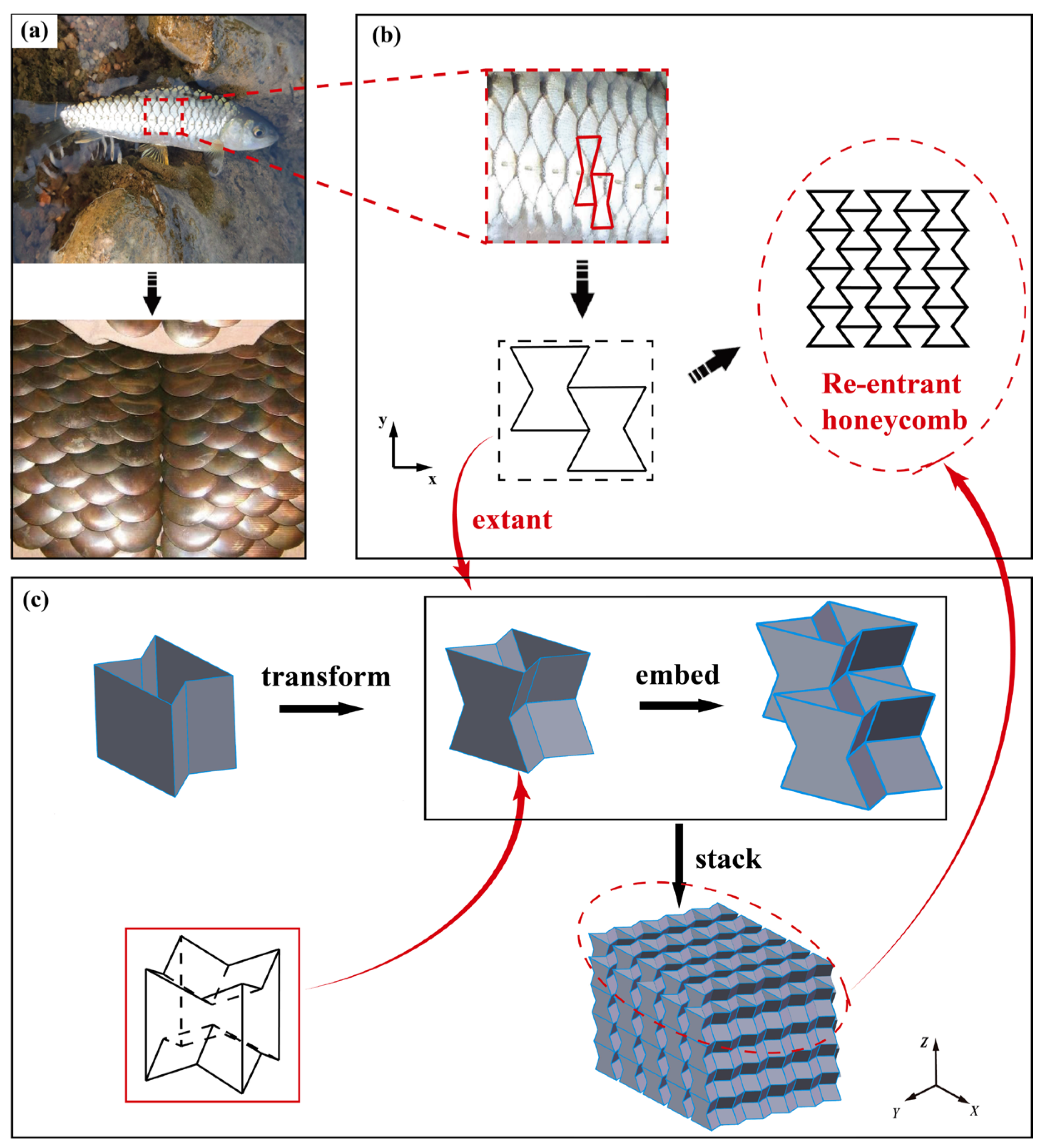
2. Theory and Design
3. Experiments and Simulation
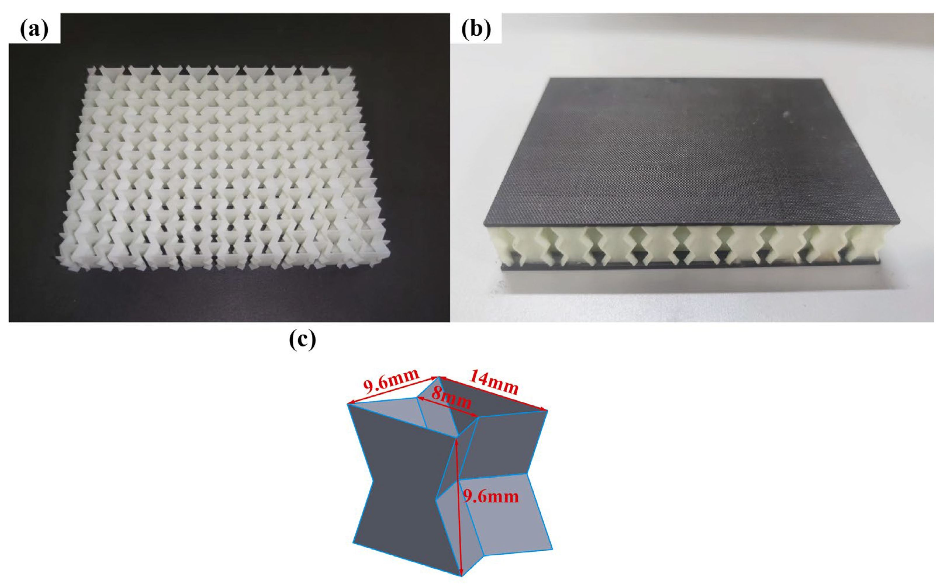
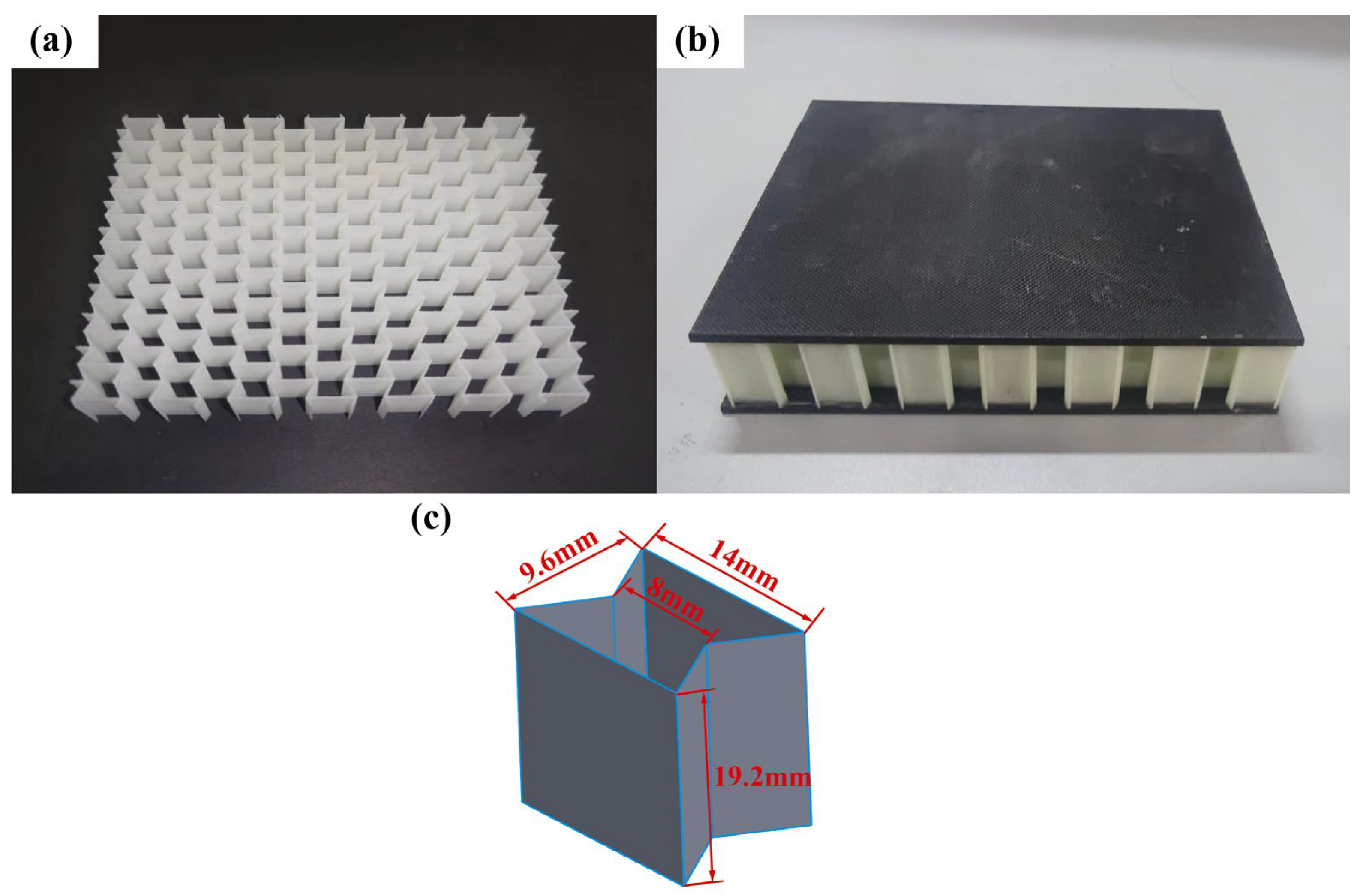
3.1. Specimen and Materials
3.2. Low-Velocity Impact Experiment
3.3. Finite Element Model
4. Results and Discussion
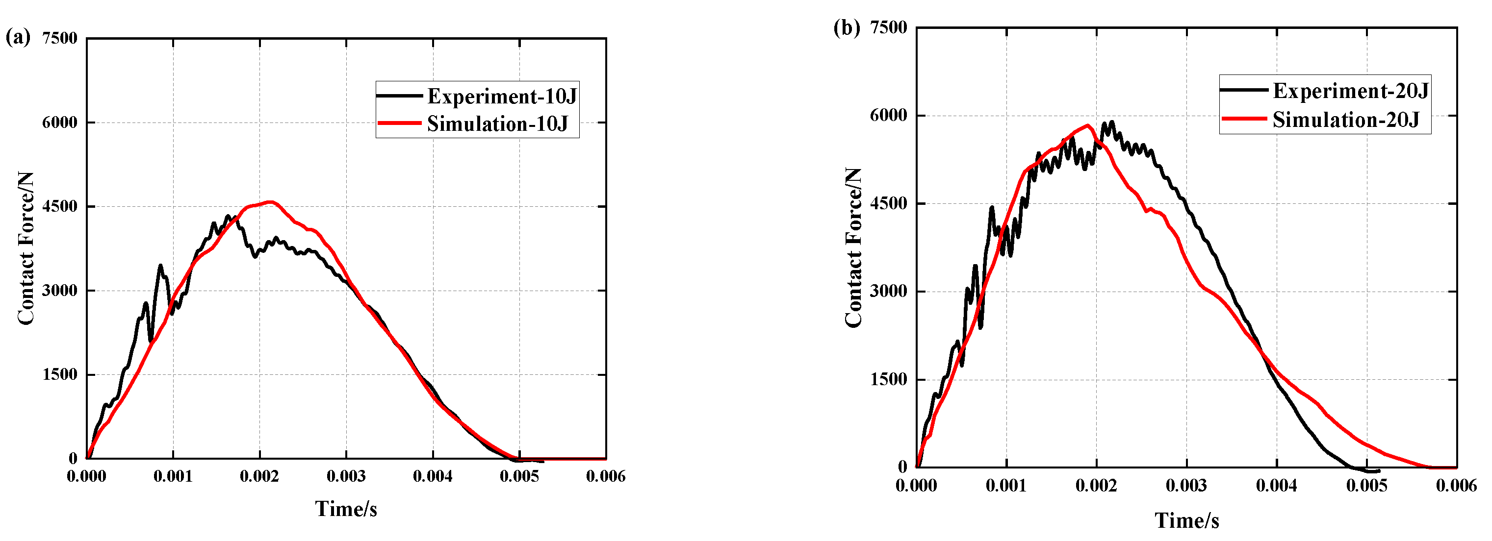
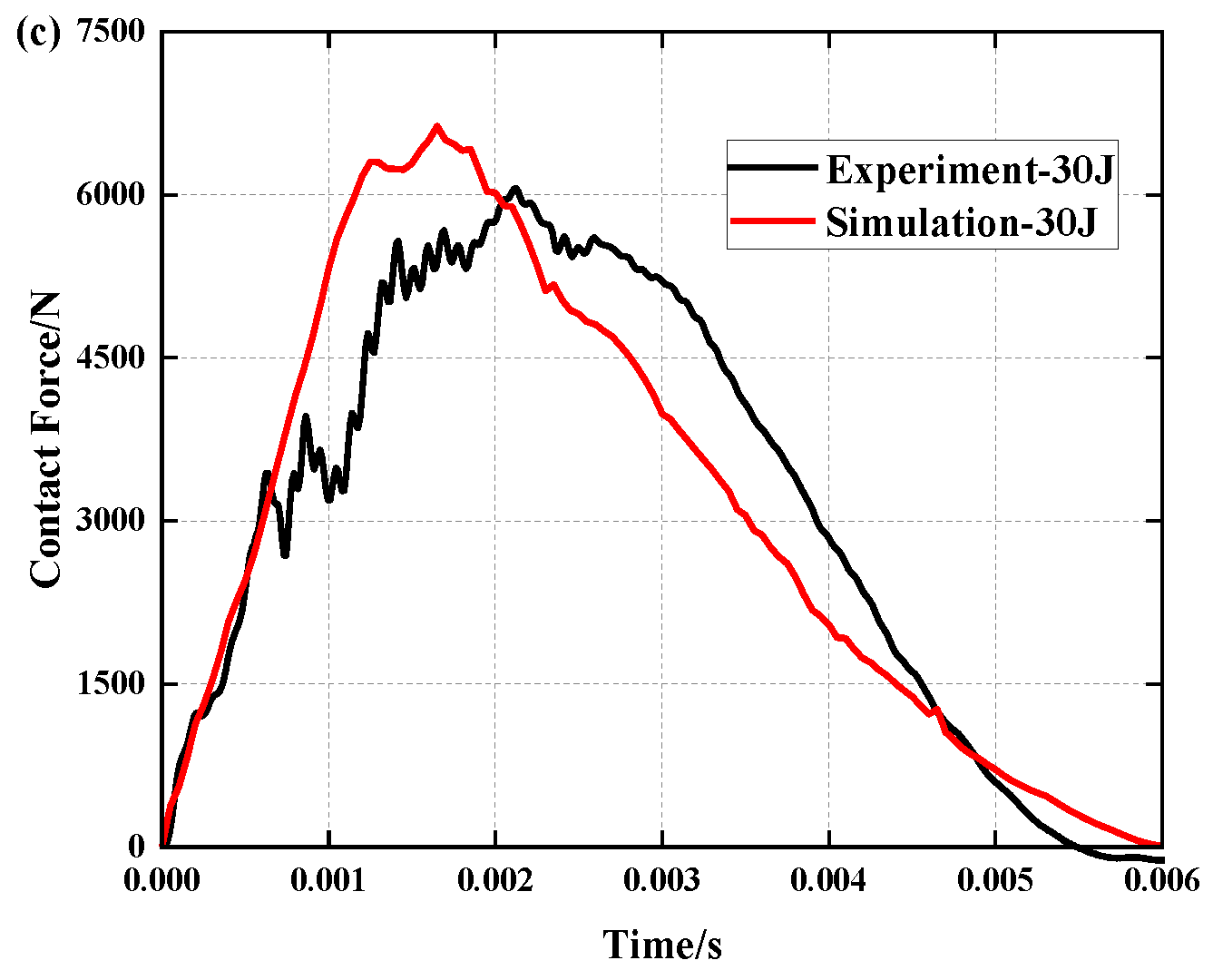
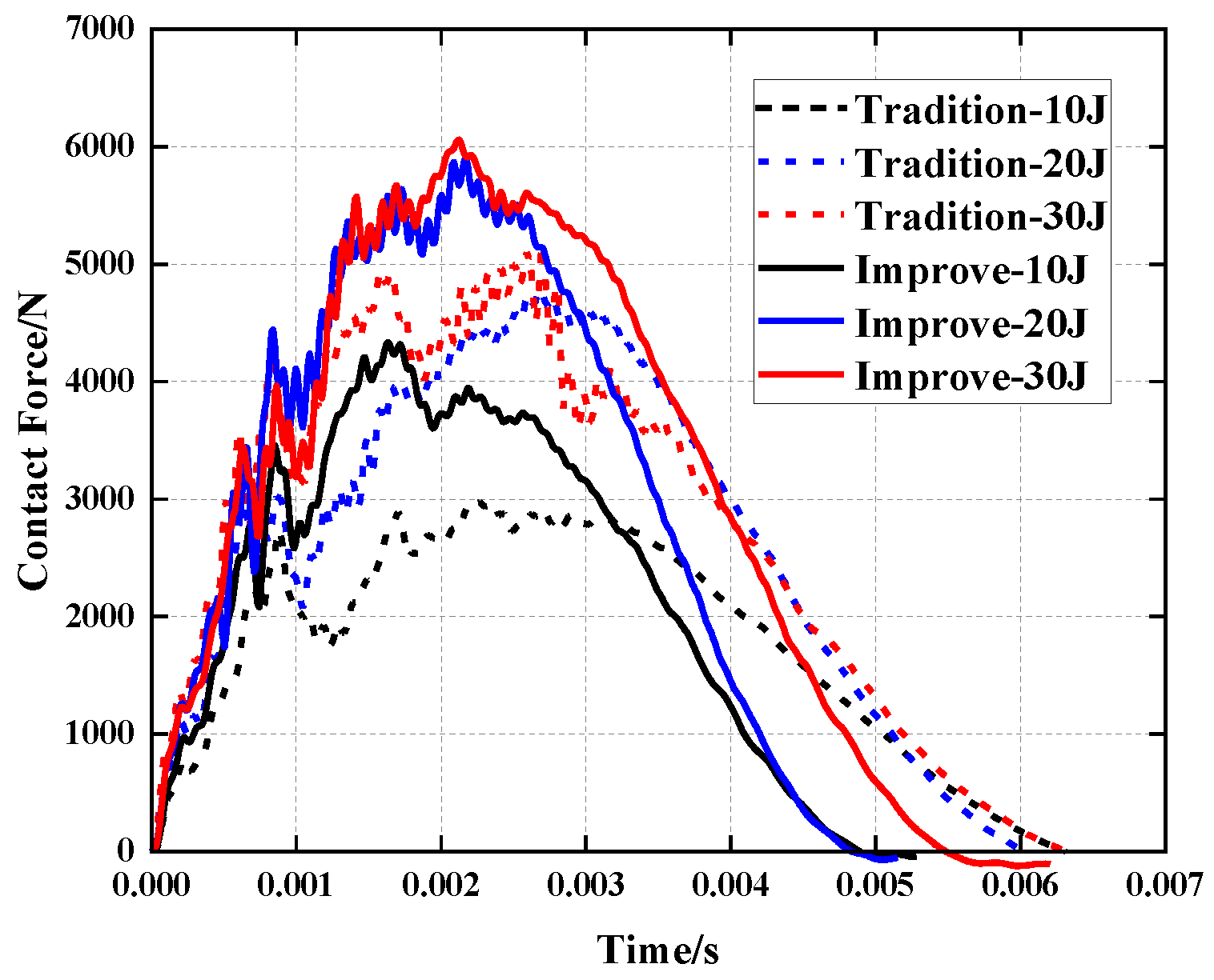
4.1. Validation of Numerical Models
4.2. Mechanical Properties Comparison with Traditional Re-Entrant Honeycomb
4.3. Effects of Geometric Parameters
4.3.1. Face Sheet Thickness
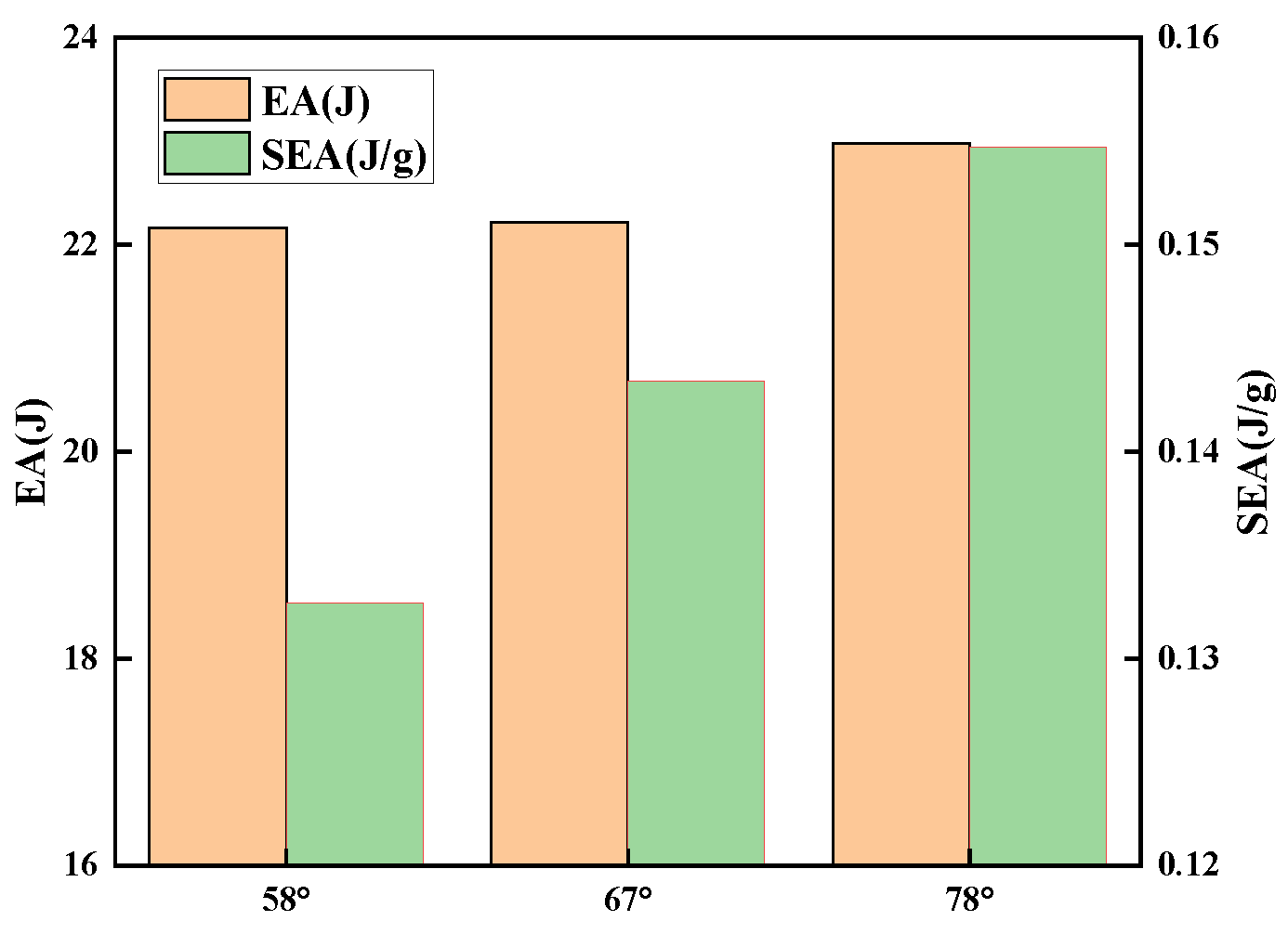
4.3.2. Concave Angle
5. Conclusions
Author Contributions
Funding
Institutional Review Board Statement
Data Availability Statement
Conflicts of Interest
References
- Bere, P.; Dudescu, M.; Neamțu, C.; Cocian, C. Design, Manufacturing and Test of CFRP Front Hood Concepts for a Light-Weight Vehicle. Polymers 2021, 13, 1374. [Google Scholar] [CrossRef]
- Duan, Y.; Zhan, Z.; Zou, T.; Tie, Y.; Cui, Z.; Wang, T. Low-Velocity Impact Resistance of Double-Layer Folded Sandwich Structure. Machines 2022, 10, 665. [Google Scholar] [CrossRef]
- Shi, S.-S.; Sun, Z.; Hu, X.-Z.; Chen, H.-R. Carbon-fiber and aluminum-honeycomb sandwich composites with and without Kevlar-fiber interfacial toughening. Compos. A Appl. Sci. Manuf. 2014, 67, 102–110. [Google Scholar] [CrossRef]
- Xue, X.; Zhang, C.; Chen, W.; Wu, M.; Zhao, J. Study on the impact resistance of honeycomb sandwich structures under low-velocity/heavy mass. Compos. Struct. 2019, 226, 111223. [Google Scholar] [CrossRef]
- Khan, M.S.; Abdul-Latif, A.; Koloor, S.S.R.; Petrů, M.; Tamin, M.N. Representative Cell Analysis for Damage-Based Failure Model of Polymer Hexagonal Honeycomb Structure under the Out-of-Plane Loadings. Polymers 2020, 13, 52. [Google Scholar] [CrossRef] [PubMed]
- He, W.; Yao, L.; Meng, X.; Sun, G.; Xie, D.; Liu, J. Effect of structural parameters on low-velocity impact behavior of aluminum honeycomb sandwich structures with CFRP face sheets. Thin-Walled Struct. 2019, 137, 411–432. [Google Scholar] [CrossRef]
- Hazizan, M.A.; Cantwell, W.J. The low velocity impact response of an aluminium honeycomb sandwich structure. Compos. B Eng. 2003, 34, 679–687. [Google Scholar] [CrossRef]
- Crupi, V.; Epasto, G.; Guglielmino, E. Collapse modes in aluminium honeycomb sandwich panels under bending and impact loading. Int. J. Impact Eng. 2012, 43, 6–15. [Google Scholar] [CrossRef]
- Ouadday, R.; Marouene, A.; Morada, G.; Kaabi, A.; Boukhili, R.; Vadean, A. Experimental and numerical investigation on the impact behavior of dual-core composite sandwich panels designed for hydraulic turbine applications. Compos. Struct. 2018, 185, 254–263. [Google Scholar] [CrossRef]
- Birman, V.; Kardomateas, G.A. Review of current trends in research and applications of sandwich structures. Compos. B Eng. 2018, 142, 221–240. [Google Scholar] [CrossRef]
- Asad, M.; Zahra, T.; Thambiratnam, D.P.; Chan, T.H.; Zhuge, Y. Geometrically modified auxetic polyurethane foams and their potential application in impact mitigation of masonry structures. Constr. Build. Mater. 2021, 311, 125170. [Google Scholar] [CrossRef]
- Gunes, R.; Arslan, K. Development of numerical realistic model for predicting low-velocity impact response of aluminium honeycomb sandwich structures. J. Sandw. Struct. Mater. 2015, 18, 95–112. [Google Scholar] [CrossRef]
- Audibert, C.; Andréani, A.-S.; Lainé, É.; Grandidier, J.-C. Discrete modelling of low-velocity impact on Nomex® honeycomb sandwich structures with CFRP skins. Compos. Struct. 2018, 207, 108–118. [Google Scholar] [CrossRef]
- Ivañez, I.; Sanchez-Saez, S. Numerical modelling of the low-velocity impact response of composite sandwich beams with honeycomb core. Compos. Struct. 2013, 106, 716–723. [Google Scholar] [CrossRef]
- Din, I.U.; Medhin, Y.; Aslam, N.; Bathusha, M.S.; Umer, R.; Khan, K.A. Rate dependent piezoresistive characterization of smart aerospace sandwich structures embedded with reduced graphene oxide (rGO) coated fabric sensors. Compos. Commun. 2022, 36, 101382. [Google Scholar] [CrossRef]
- Han, Q.; Qin, H.; Han, Z.; Zhang, J.; Niu, S.; Sun, Y.; Shi, S. Study on mechanical properties of multi-structure dactyl-inspired sandwich honeycomb with basalt fiber. Compos. Struct. 2020, 247, 112467. [Google Scholar] [CrossRef]
- Shin, K.; Lee, J.Y.; Cho, S.H. An experimental study of low-velocity impact responses of sandwich panels for Korean low floor bus. Compos. Struct. 2008, 84, 228–240. [Google Scholar] [CrossRef]
- Langdon, G.; Nurick, G.; Yahya, M.; Cantwell, W. The Response of Honeycomb Core Sandwich Panels, with Aluminum and Composite Face Sheets, to Blast Loading. J. Sandw. Struct. Mater. 2010, 12, 733–754. [Google Scholar] [CrossRef]
- Qi, J.; Li, C.; Tie, Y.; Zheng, Y.; Duan, Y. Energy absorption characteristics of origami-inspired honeycomb sandwich structures under low-velocity impact loading. Mater. Des. 2021, 207, 109837. [Google Scholar] [CrossRef]
- Qi, C.; Jiang, F.; Yang, S. Advanced honeycomb designs for improving mechanical properties: A review. Compos. B Eng. 2021, 227, 109393. [Google Scholar] [CrossRef]
- Yang, K.; Li, Z.; Ge, D. Quasi-static and dynamic out-of-plane crashworthiness of 3D curved-walled mixed-phase honeycombs. Thin-Walled Struct. 2023, 182, 110305. [Google Scholar] [CrossRef]
- Baertsch, F.; Ameli, A.; Mayer, T. Finite-Element Modeling and Optimization of 3D-Printed Auxetic Reentrant Structures with Stiffness Gradient under Low-Velocity Impact. J. Eng. Mech. 2021, 147, 04021036. [Google Scholar] [CrossRef]
- Cui, Z.; Qi, J.; Tie, Y.; Zou, T.; Duan, Y. Research on the energy absorption properties of origami-based honeycombs. Thin-Walled Struct. 2023, 184, 110520. [Google Scholar] [CrossRef]
- Hedayatian, M.; Daneshmehr, A.R.; Liaghat, G.H. The Efficiency of Auxetic Cores in Sandwich Beams Subjected to Low-Velocity Impact. Int. J. Appl. Mech. 2020, 12, 2050061. [Google Scholar] [CrossRef]
- Najafi, M.; Ahmadi, H.; Liaghat, G. Investigation on the flexural properties of sandwich beams with auxetic core. J. Braz. Soc. Mech. Sci. Eng. 2022, 44, 61. [Google Scholar] [CrossRef]
- Yang, S.; Qi, C.; Wang, D.; Gao, R.; Hu, H.; Shu, J. A Comparative Study of Ballistic Resistance of Sandwich Panels with Aluminum Foam and Auxetic Honeycomb Cores. Adv. Mech. Eng. 2013, 5, 589216. [Google Scholar] [CrossRef]
- Qi, C.; Remennikov, A.; Pei, L.-Z.; Yang, S.; Yu, Z.-H.; Ngo, T.D. Impact and close-in blast response of auxetic honeycomb-cored sandwich panels: Experimental tests and numerical simulations. Compos. Struct. 2017, 180, 161–178. [Google Scholar] [CrossRef]
- Hou, S.; Li, T.; Jia, Z.; Wang, L. Mechanical properties of sandwich composites with 3d-printed auxetic and non-auxetic lattice cores under low velocity impact. Mater. Des. 2018, 160, 1305–1321. [Google Scholar] [CrossRef]
- Li, C.; Shen, H.-S.; Yang, J.; Wang, H. Low-velocity impact response of sandwich plates with GRC face sheets and FG auxetic 3D lattice cores. Eng. Anal. Bound. Elem. 2021, 132, 335–344. [Google Scholar] [CrossRef]
- Li, C.; Shen, H.-S.; Yang, J. Multi-scale modeling and numerical analysis of sandwich beams with FG auxetic 3D lattice cores and GRC face sheets subjected to drop-weight impacts. Eng. Struct. 2022, 265, 114486. [Google Scholar] [CrossRef]
- Meng, L.; Shi, J.; Yang, C.; Gao, T.; Hou, Y.; Song, L.; Gu, D.; Zhu, J.; Breitkopf, P.; Zhang, W. An emerging class of hyperbolic lattice exhibiting tunable elastic properties and impact absorption through chiral twisting. Extreme Mech. Lett. 2020, 40, 100869. [Google Scholar] [CrossRef]
- Liu, K.; Jiang, L. Bio-inspired design of multiscale structures for function integration. Nano Today 2011, 6, 155–175. [Google Scholar] [CrossRef]
- Plessis, A.; Broeckhoven, C.; Yadroitsev, I.; Yadroitsava, I.; le Roux, S.G. Analyzing nature’s protective design: The glyptodont body armor. J. Mech. Behav. Biomed. Mater. 2018, 82, 218–223. [Google Scholar] [CrossRef]
- Zhang, Y.; Wang, J.; Wang, C.; Zeng, Y.; Chen, T. Crashworthiness of bionic fractal hierarchical structures. Mater. Des. 2018, 158, 147–159. [Google Scholar] [CrossRef]
- Yang, X.; Xi, X.; Pan, Q.; Liu, H. In-plane dynamic crushing of a novel circular-celled honeycomb nested with petal-shaped mesostructure. Compos. Struct. 2019, 226, 111219. [Google Scholar] [CrossRef]
- Zhang, X.-C.; An, C.-C.; Shen, Z.-F.; Wu, H.-X.; Yang, W.-G.; Bai, J.-P. Dynamic crushing responses of bio-inspired re-entrant auxetic honeycombs under in-plane impact loading. Mater. Today Commun. 2020, 23, 100918. [Google Scholar] [CrossRef]
- Hao, P.; Du, J. Energy absorption characteristics of bio-inspired honeycomb column thin-walled structure under impact loading. J. Mech. Behav. Biomed. Mater. 2018, 79, 301–308. [Google Scholar] [CrossRef]
- Tsang, H.; Raza, S. Impact energy absorption of bio-inspired tubular sections with structural hierarchy. Compos. Struct. 2018, 195, 199–210. [Google Scholar] [CrossRef]
- Yu, X.; Pan, L.; Chen, J.; Zhang, X.; Wei, P. Experimental and numerical study on the energy absorption abilities of trabecular–honeycomb biomimetic structures inspired by beetle elytra. J. Mater. Sci. 2019, 54, 2193–2204. [Google Scholar] [CrossRef]
- ASTM D7766/D7766M-16; Standard Practice for Damage Resistance Testing of Sandwich Constructions. ASTM International: West Conshohocken, PA, USA, 2016.
- Duan, Y.; Cui, Z.; Xie, X.; Tie, Y.; Zou, T.; Wang, T. Mechanical characteristics of composite honeycomb sandwich structures under oblique impact. Theor. Appl. Mech. Lett. 2022, 12, 100379. [Google Scholar] [CrossRef]
- ASTM D7136/D7136M-07; Standard Test Method for Measuring the Damage Resistance of a Fiber-Reinforced Polymer Matrix Composite to a Drop-Weight Impact Event. ASTM International: West Conshohocken, PA, USA, 2003.
- Din, I.U.; Panier, S.; Hao, P.; Franz, G.; Bijwe, J.; Hui, L. Finite element modeling of indentation and adhesive wear in sliding of carbon fiber reinforced thermoplastic polymer against metallic counterpart. Tribol. Int. 2019, 135, 200–212. [Google Scholar] [CrossRef]


| Properties | T300/7901 | Properties | Inter-Laminar Adhesive |
|---|---|---|---|
| Materials | Density (kg/m3) | Young’s Modulus (GPa) | Poisson’s Ratio | Yield Stress (MPa) | Tensile Strength (MPa) | Failure Strain |
|---|---|---|---|---|---|---|
| Godart ®8228 | 1180 | 2.1 | 0.35 | - | 51.21 | 0.16 |
| Araldite 2015 | 1400 | 1.85 | 0.33 | 12.63 | 21.63 | 0.047 |
| Energy/J | Experimental Value/N | Simulation Value/N | Deviation/N | Relative Error/% |
|---|---|---|---|---|
| 10 | 4335.57 | 4584.32 | 248.75 | 5.74 |
| 20 | 5897.92 | 5832.76 | 65.16 | 1.10 |
| 30 | 6058.96 | 6632.77 | 573.81 | 9.47 |
| Energy/J | Experimental Value/ms | Simulation Value/ms | Deviation/ms |
|---|---|---|---|
| 10 | 4.896 | 4.95 | 0.054 |
| 20 | 4.848 | 5.70 | 0.852 |
| 30 | 5.484 | 6.00 | 0.516 |
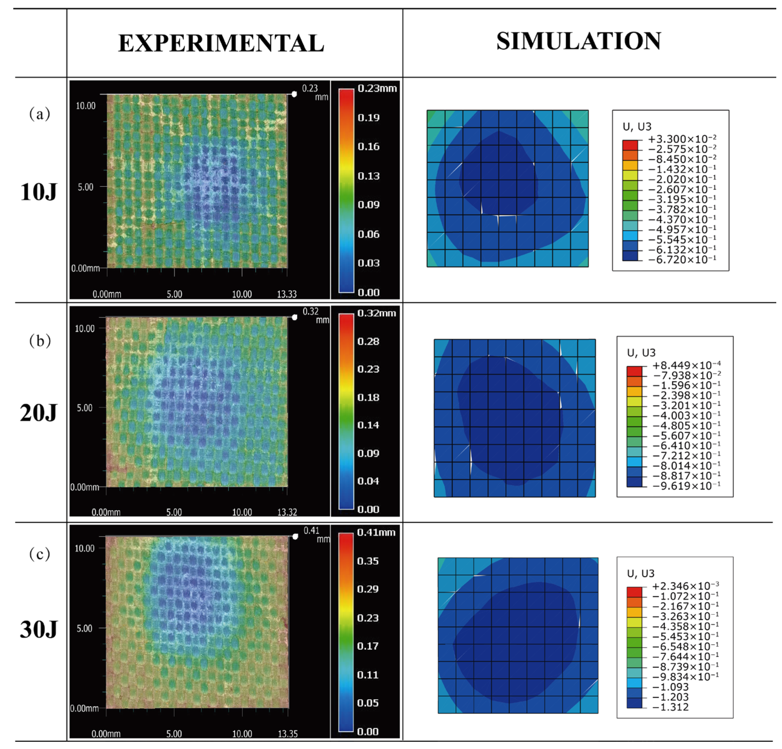
| Energy/J | Traditional Structures/mm | Improved Structure/mm |
|---|---|---|
| 10 | 0.27 | 0.23 |
| 20 | 0.35 | 0.32 |
| 30 | 0.47 | 0.41 |
Disclaimer/Publisher’s Note: The statements, opinions and data contained in all publications are solely those of the individual author(s) and contributor(s) and not of MDPI and/or the editor(s). MDPI and/or the editor(s) disclaim responsibility for any injury to people or property resulting from any ideas, methods, instructions or products referred to in the content. |
© 2023 by the authors. Licensee MDPI, Basel, Switzerland. This article is an open access article distributed under the terms and conditions of the Creative Commons Attribution (CC BY) license (https://creativecommons.org/licenses/by/4.0/).
Share and Cite
Cui, Z.; Qi, J.; Duan, Y.; Tie, Y.; Zheng, Y.; Yang, J.; Li, C. Low-Velocity Impact Resistance of 3D Re-Entrant Honeycomb Sandwich Structures with CFRP Face Sheets. Polymers 2023, 15, 1092. https://doi.org/10.3390/polym15051092
Cui Z, Qi J, Duan Y, Tie Y, Zheng Y, Yang J, Li C. Low-Velocity Impact Resistance of 3D Re-Entrant Honeycomb Sandwich Structures with CFRP Face Sheets. Polymers. 2023; 15(5):1092. https://doi.org/10.3390/polym15051092
Chicago/Turabian StyleCui, Zhen, Jiaqi Qi, Yuechen Duan, Ying Tie, Yanping Zheng, Jun Yang, and Cheng Li. 2023. "Low-Velocity Impact Resistance of 3D Re-Entrant Honeycomb Sandwich Structures with CFRP Face Sheets" Polymers 15, no. 5: 1092. https://doi.org/10.3390/polym15051092