
Proposal and Design of Flexible All-Polymer/CIGS Tandem Solar Cell

Abstract
:1. Introduction
2. Simulation Procedure and Device Construction
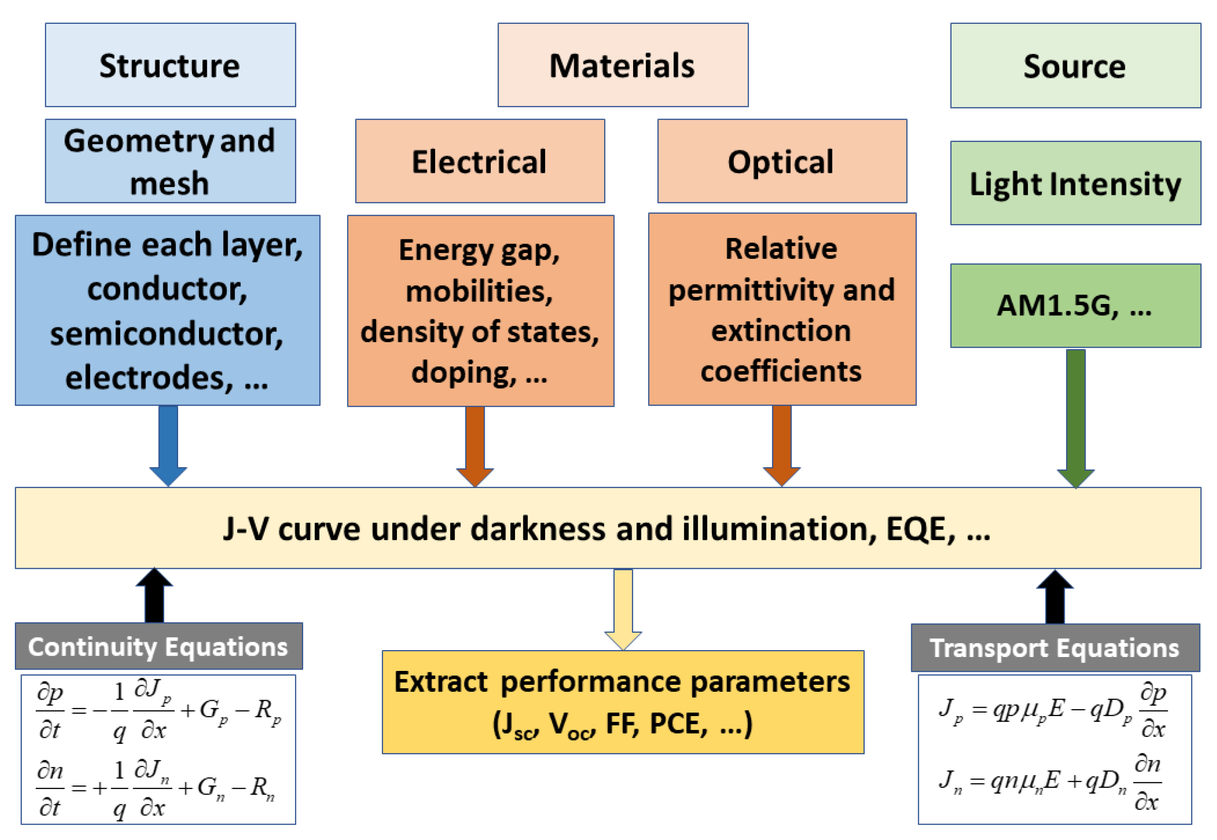
2.1. Silvaco Simulation Platform
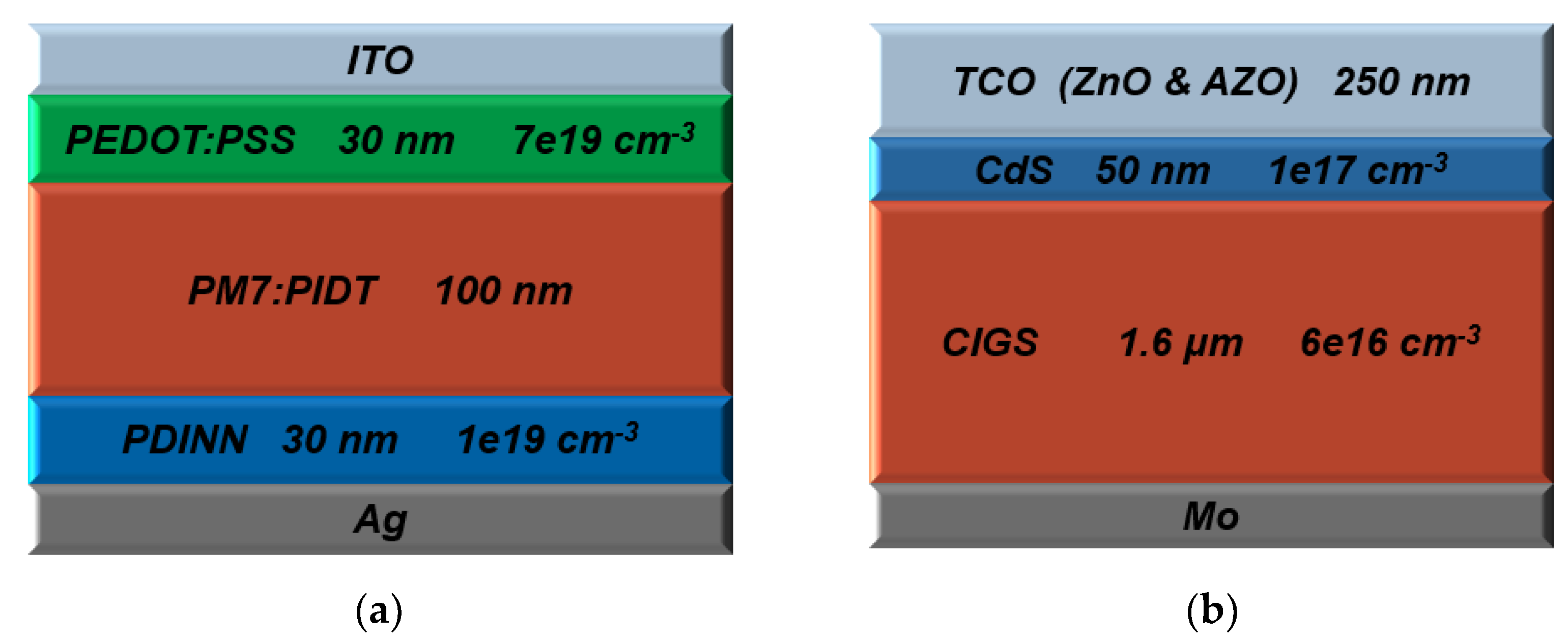
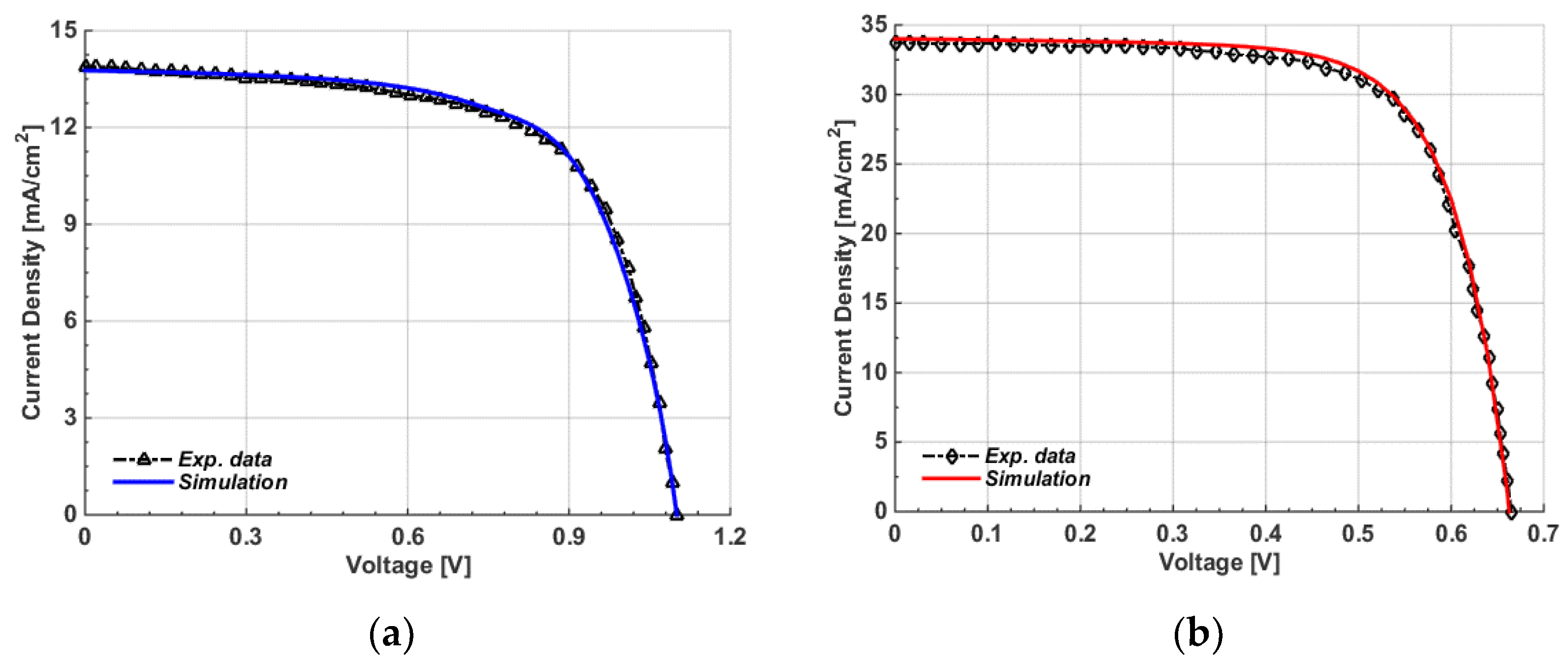
2.2. Top and Bottom Subcell Device Structures and Calibration
3. Results and Discussion
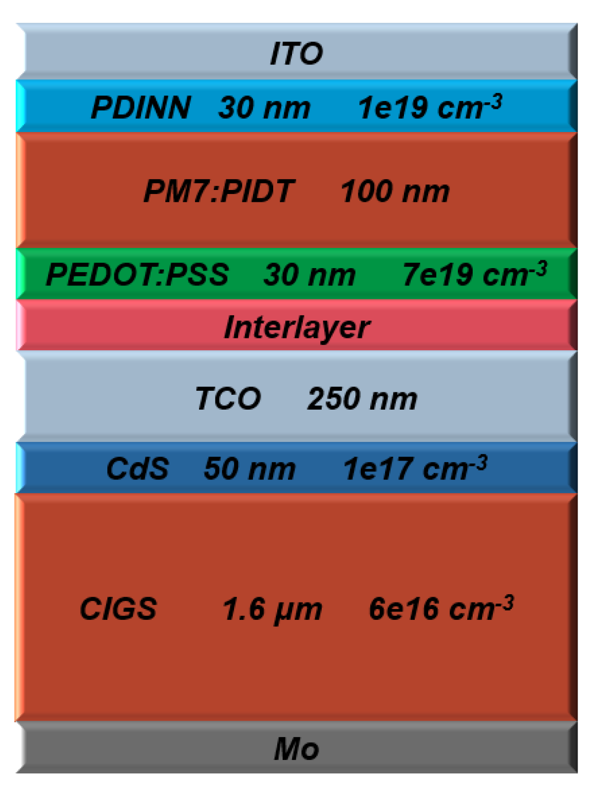
3.1. Initial Polymer/CIGS Tandem Design
3.2. Optimization of Band Alignment
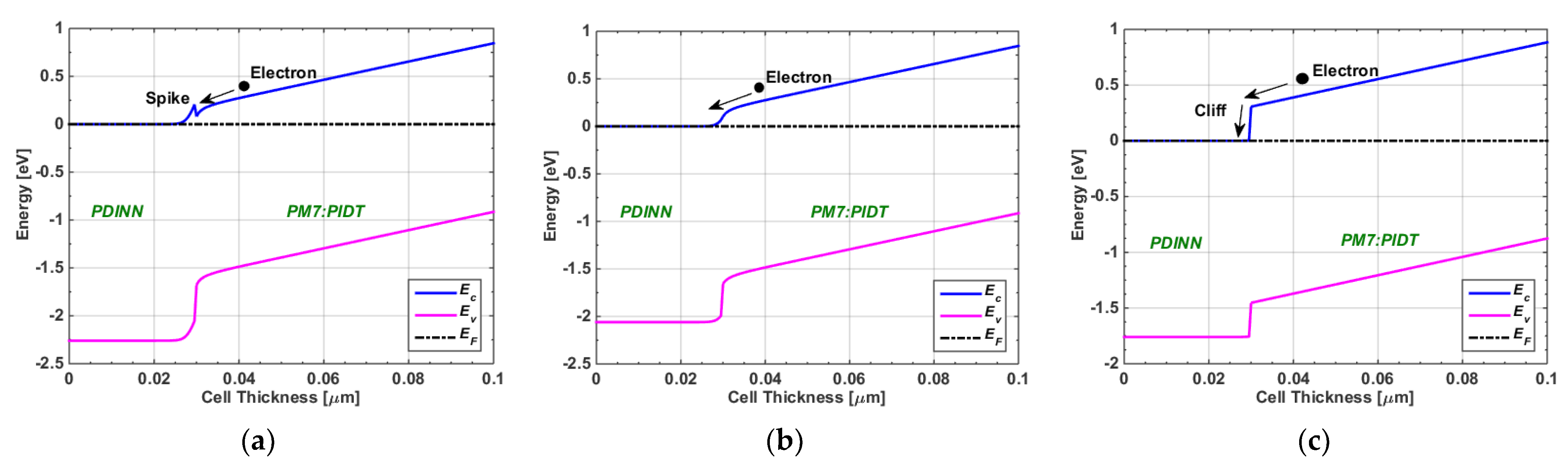
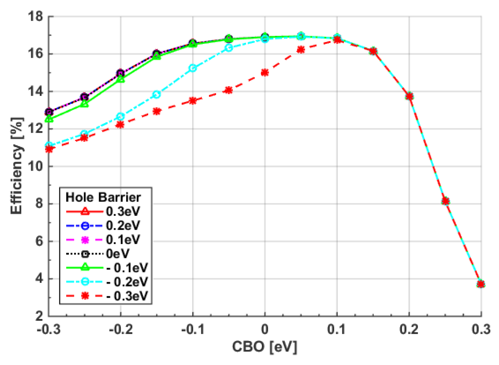
3.2.1. Impact of CBO of Top Subcell
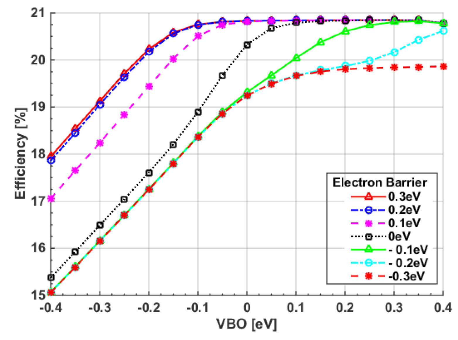
3.2.2. Impact of VBO of Top Subcell
3.2.3. Optimum ETL and HTL Top Subcell Materials
3.3. Optimization of Polymer and CIGS Thickness
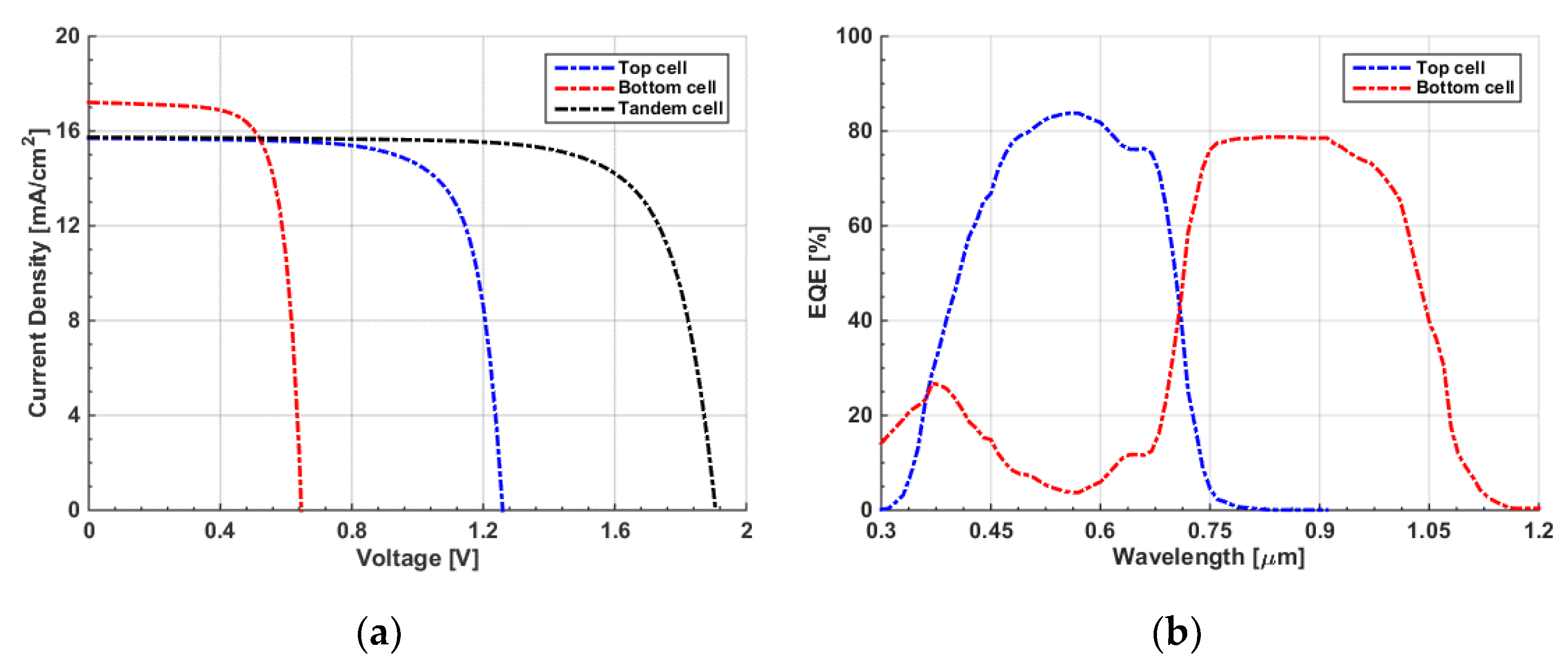
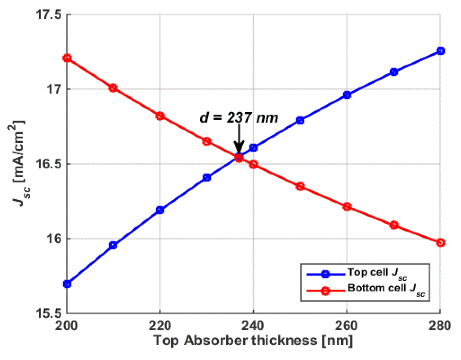
3.4. Current Matching Point Simulation
4. Conclusions
Supplementary Materials
Author Contributions
Funding
Institutional Review Board Statement
Data Availability Statement
Conflicts of Interest
References
- International Energy Agency. Renewables 2019, Market Analysis and Forecast from 2019 to 2024. IEA Reports. 2019. Available online: https://www.iea.org/reports/renewables-2019 (accessed on 10 February 2023).
- Okil, M.; Salem, M.S.; Abdolkader, T.M.; Shaker, A. From Crystalline to Low-cost Silicon-based Solar Cells: A Review. Silicon 2021, 14, 1895–1911. [Google Scholar] [CrossRef]
- Yoshikawa, K.; Kawasaki, H.; Yoshida, W.; Irie, T.; Konishi, K.; Nakano, K.; Uto, T.; Adachi, D.; Kanematsu, M.; Uzu, H.; et al. Silicon heterojunction solar cell with interdigitated back contacts for a photoconversion efficiency Over 26%. Nat. Energy 2017, 2, 17032. [Google Scholar] [CrossRef]
- Ben Rabha, M.; Mohamed, S.B.; Dimassi, W.; Gaidi, M.; Ezzaouia, H.; Bessais, B. Optoelectronic enhancement of monocrystalline silicon solar cells by porous silicon-assisted mechanical grooving. Phys. Status Solidi C 2011, 8, 887–890. [Google Scholar] [CrossRef]
- Ben Rabha, M.; Khezami, L.; Jemai, A.B.; Alhathlool, R.; Ajbar, A. Surface passivation of silicon nanowires based metal nano-particle assisted chemical etching for photovoltaic applications. J. Cryst. Growth 2017, 462, 35–40. [Google Scholar] [CrossRef]
- Eisenlohr, J.; Tucher, N.; Hauser, H.; Graf, M.; Benick, J.; Bläsi, B.; Goldschmidt, J.C.; Hermle, M. Efficiency increase of crystalline silicon solar cells with nanoimprinted rear side gratings for enhanced light trapping. Sol. Energy Mater. Sol. Cells 2016, 155, 288–293. [Google Scholar] [CrossRef]
- Sun, P.; Xu, P.; Zhu, K.; Zhou, Z. Silicon-Based Optoelectronics Enhanced by Hybrid Plasmon Polaritons: Bridging Dielectric Photonics and Nanoplasmonics. Photonics 2021, 8, 482. [Google Scholar] [CrossRef]
- Zekry, A. A road map for transformation from conventional to photovoltaic energy generation and its challenges. J. King Saud Univ. Eng. Sci. 2020, 32, 407–410. [Google Scholar] [CrossRef]
- Salem, M.S.; Zekry, A.; Shaker, A.; Abouelatta, M. Design and simulation of proposed low cost solar cell structures based on heavily doped silicon wafers. In Proceedings of the 2016 IEEE 43rd Photovoltaic Specialists Conference (PVSC), Portland, OR, USA, 5–10 June 2016. [Google Scholar] [CrossRef]
- Zhang, Y.; Fan, Z.; Zhang, W.; Ma, Q.; Jiang, Z.; Ma, D. High performance hybrid silicon micropillar solar cell based on light trapping characteristics of Cu nanoparticles. AIP Adv. 2018, 8, 055309. [Google Scholar] [CrossRef] [Green Version]
- Zhang, Y.; Liu, H. Nanowires for High-Efficiency, Low-Cost Solar Photovoltaics. Crystals 2019, 9, 87. [Google Scholar] [CrossRef] [Green Version]
- Salem, M.S.; Alzahrani, A.J.; Ramadan, R.A.; Alanazi, A.; Shaker, A.; Abouelatta, M.; Zekry, A. Physically based analytical model of heavily doped silicon wafers based proposed solar cell microstructure. IEEE Access 2020, 8, 138898–138906. [Google Scholar] [CrossRef]
- Bista, S.S.; Li, D.B.; Rijal, S.; Neupane, S.; Awni, R.A.; Jiang, C.S.; Xiao, C.; Subedi, K.K.; Song, Z.; Phillips, A.B.; et al. Water-Assisted Lift-Off Process for Flexible CdTe Solar Cells. ACS Appl. Energy Mater. 2023, 6, 885–891. [Google Scholar] [CrossRef]
- Salhi, B. The Photovoltaic Cell Based on CIGS: Principles and Technologies. Materials 2022, 15, 1908. [Google Scholar] [CrossRef]
- Mabvuer, F.T.; Nya, F.T.; Dzifack Kenfack, G.M.; Laref, A. Lowering Cost Approach for CIGS-Based Solar Cell Through Optimizing Band Gap Profile and Doping of Stacked Active Layers—SCAPS Modeling. ACS Omega 2023, 8, 3917–3928. [Google Scholar] [CrossRef]
- Lee, C.; Lee, S.; Kim, G.U.; Lee, W.; Kim, B.J. Recent advances, design guidelines, and prospects of all-polymer solar cells. Chem. Rev. 2019, 119, 8028–8086. [Google Scholar] [CrossRef]
- Li, Y.; Huang, W.; Zhao, D.; Wang, L.; Jiao, Z.; Huang, Q.; Wang, P.; Sun, M.; Yuan, G. Recent progress in organic solar cells: A review on materials from acceptor to donor. Molecules 2022, 27, 1800. [Google Scholar] [CrossRef] [PubMed]
- Alanazi, T.I. Current Spray-Coating Approaches to Manufacture Perovskite Solar Cells. Results Phys. 2023, 44, 106144. [Google Scholar] [CrossRef]
- Liang, X.; Ge, C.; Fang, Q.; Deng, W.; Dey, S.; Lin, H.; Zhang, Y.; Zhang, X.; Zhu, Q.; Hu, H. Flexible perovskite solar cells: Progress and Prospects. Front. Mater. 2021, 8, 634353. [Google Scholar] [CrossRef]
- Hu, Y.; Niu, T.; Liu, Y.; Zhou, Y.; Xia, Y.; Ran, C.; Wu, Z.; Song, L.; Müller-Buschbaum, P.; Chen, Y.; et al. Flexible perovskite solar cells with high power-per-weight: Progress, application, and perspectives. ACS Energy Lett. 2021, 6, 2917–2943. [Google Scholar] [CrossRef]
- Salem, M.S.; Shaker, A.; Abouelatta, M.; Saeed, A. Full Optoelectronic Simulation of Lead-Free Perovskite/Organic Tandem Solar Cells. Polymers 2023, 15, 784. [Google Scholar] [CrossRef]
- Sivaraj, S.; Rathanasamy, R.; Kaliyannan, G.V.; Panchal, H.; Jawad Alrubaie, A.; Musa Jaber, M.; Said, Z.; Memon, S. A Comprehensive Review on Current Performance, Challenges and Progress in Thin-Film Solar Cells. Energies 2022, 15, 8688. [Google Scholar] [CrossRef]
- Efaz, E.T.; Rhaman, M.M.; Al Imam, S.; Bashar, K.L.; Kabir, F.; Mourtaza, M.E.; Sakib, S.N.; Mozahid, A.F. A review of primary technologies of thin-film solar cells. Eng. Res. Express 2021, 3, 032001. [Google Scholar] [CrossRef]
- Ruiz-Preciado, M.A.; Gota, F.; Fassl, P.; Hossain, I.M.; Singh, R.; Laufer, F.; Schackmar, F.; Feeney, T.; Farag, A.; Allegro, I.; et al. Monolithic Two-Terminal Perovskite/CIS Tandem Solar Cells with Efficiency Approaching 25%. ACS Energy Lett. 2022, 7, 2273–2281. [Google Scholar] [CrossRef]
- Abdelaziz, S.; Zekry, A.; Shaker, A.; Abouelatta, M. Investigation of lead-free MASnI3-MASnIBr2 tandem solar cell: Numerical simulation. Opt. Mater. 2022, 123, 111893. [Google Scholar] [CrossRef]
- Chen, X.; Jia, Z.; Chen, Z.; Jiang, T.; Bai, L.; Tao, F.; Yang, Y.M. Efficient and reproducible monolithic perovskite/organic tandem solar cells with low-loss interconnecting layers. Joule 2020, 4, 1594–1606. [Google Scholar] [CrossRef]
- Okil, M.; Shaker, A.; Ahmed, I.S.; Abdolkader, T.M.; Salem, M.S. Design and analysis of Sb2S3/Si thin film tandem solar cell. Sol. Energy Mater. Sol. Cells 2023, 253, 112210. [Google Scholar] [CrossRef]
- Lin, R.; Xu, J.; Wei, M.; Wang, Y.; Qin, Z.; Liu, Z.; Wu, J.; Xiao, K.; Chen, B.; Park, S.M.; et al. All-perovskite tandem solar cells with improved grain surface passivation. Nature 2022, 603, 73–78. [Google Scholar] [CrossRef]
- Saeed, A.; Salah, M.M.; Zekry, A.; Mousa, M.; Shaker, A.; Abouelatta, M.; Amer, F.Z.; Mubarak, R.I.; Louis, D.S. Investigation of High-Efficiency and Stable Carbon-Perovskite/Silicon and Carbon-Perovskite/CIGS-GeTe Tandem Solar Cells. Energies 2023, 16, 1676. [Google Scholar] [CrossRef]
- Min, H.; Lee, D.Y.; Kim, J.; Kim, G.; Lee, K.S.; Kim, J.; Paik, M.J.; Kim, Y.K.; Kim, K.S.; Kim, M.G.; et al. Perovskite solar cells with atomically coherent interlayers on SnO2 electrodes. Nature 2021, 598, 444–450. [Google Scholar] [CrossRef]
- Jošt, M.; Köhnen, E.; Al-Ashouri, A.; Bertram, T.; Tomšič, S.; Magomedov, A.; Kasparavicius, E.; Kodalle, T.; Lipovšek, B.; Getautis, V.; et al. Perovskite/CIGS tandem solar cells: From certified 24.2% toward 30% and beyond. ACS Energy Lett. 2022, 7, 1298–1307. [Google Scholar] [CrossRef]
- Feurer, T.; Reinhard, P.; Avancini, E.; Bissig, B.; Löckinger, J.; Fuchs, P.; Carron, R.; Weiss, T.P.; Perrenoud, J.; Stutterheim, S.; et al. Progress in thin film CIGS photovoltaics–Research and development, manufacturing, and applications. Prog. Photovolt. Res. Appl. 2017, 25, 645–667. [Google Scholar] [CrossRef]
- Luo, J.; Tang, L.; Wang, S.; Yan, H.; Wang, W.; Chi, Z.; Gong, J.; Li, J.; Xiao, X. Manipulating Ga growth profile enables all-flexible high-performance single-junction CIGS and 4 T perovskite/CIGS tandem solar cells. Chem. Eng. J. 2023, 455, 140960. [Google Scholar] [CrossRef]
- Xu, Y.; Yuan, J.; Zhou, S.; Seifrid, M.; Ying, L.; Li, B.; Huang, F.; Bazan, G.C.; Ma, W. Ambient Processable and Stable All-Polymer Organic Solar Cells. Adv. Funct. Mater. 2019, 29, 1806747. [Google Scholar] [CrossRef]
- Wang, J.; Cui, Y.; Xu, Y.; Xian, K.; Bi, P.; Chen, Z.; Zhou, K.; Ma, L.; Zhang, T.; Yang, Y.; et al. A New Polymer Donor Enables Binary All-Polymer Organic Photovoltaic Cells with 18% Efficiency and Excellent Mechanical Robustness. Adv. Mater. 2022, 34, 2205009. [Google Scholar] [CrossRef]
- Yuan, J.; Gu, J.; Shi, G.; Sun, J.; Wang, H.Q.; Ma, W. High efficiency all-polymer tandem solar cells. Sci. Rep. 2016, 6, 26459. [Google Scholar] [CrossRef] [PubMed] [Green Version]
- Yuan, J.; Ford, M.J.; Xu, Y.; Zhang, Y.; Bazan, G.C.; Ma, W. Improved Tandem All-Polymer Solar Cells Performance by Using Spectrally Matched Subcells. Adv. Energy Mater. 2018, 8, 1703291. [Google Scholar] [CrossRef]
- Ma, Q.; Jia, Z.; Meng, L.; Yang, H.; Zhang, J.; Lai, W.; Guo, J.; Jiang, X.; Cui, C.; Li, Y. 17.87% Efficiency All-Polymer Tandem Solar Cell Enabled by Complementary Absorbing Polymer Acceptors. Adv. Funct. Mater. 2022, 33, 2210733. [Google Scholar] [CrossRef]
- Zang, Y.; Xin, Q.; Zhao, J.; Lin, J. Effect of active layer thickness on the performance of polymer solar cells based on a highly efficient donor material of PTB7-Th. J. Phys. Chem. C 2018, 122, 16532–16539. [Google Scholar] [CrossRef]
- Abdelaziz, W.; Zekry, A.; Shaker, A.; Abouelatta, M. Numerical study of organic graded bulk heterojunction solar cell using SCAPS simulation. Sol. Energy 2020, 211, 375–382. [Google Scholar] [CrossRef]
- Alahmadi, A.N.M. Design of an Efficient PTB7:PC70BM-Based Polymer Solar Cell for 8% Efficiency. Polymers 2022, 14, 889. [Google Scholar] [CrossRef]
- Moiz, S.A.; Alzahrani, M.S.; Alahmadi, A.N.M. Electron Transport Layer Optimization for Efficient PTB7:PC70BM Bulk-Heterojunction Solar Cells. Polymers 2022, 14, 3610. [Google Scholar] [CrossRef]
- Salem, M.S.; Shaker, A.; Salah, M.M. Device Modeling of Efficient PBDB-T:PZT-Based All-Polymer Solar Cell: Role of Band Alignment. Polymers 2023, 15, 869. [Google Scholar] [CrossRef] [PubMed]
- Heriche, H.; Rouabah, Z.; Bouarissa, N. High-efficiency CIGS solar cells with optimization of layers thickness and doping. Optik 2016, 127, 11751–11757. [Google Scholar] [CrossRef]
- Liu, J.; Zhang, M.; Feng, X. Simulation of graded bandgap on the performance of back-wall superstrate CIGS solar cells. Optik 2018, 172, 1172–1178. [Google Scholar] [CrossRef]
- Sajeev, C.; Abraham, N.; Sreevidhya, K.L. Defect states and grading induced bandgap variability analysis of CIGS solar cells through device simulations. Mater. Today Proc. 2021, 43, 3729–3734. [Google Scholar] [CrossRef]
- Hedayati, M.; Olyaee, S. High-Efficiency p-n Homojunction Perovskite and CIGS Tandem Solar Cell. Crystals 2022, 12, 703. [Google Scholar] [CrossRef]
- Salah, M.M.; Zekry, A.; Shaker, A.; Abouelatta, M.; Mousa, M.; Saeed, A. Investigation of Electron Transport Material-Free Perovskite/CIGS Tandem Solar Cell. Energies 2022, 15, 6326. [Google Scholar] [CrossRef]
- Kumari, D.; Pandey, S.K. Effect of an ultra-thin 2D transport layer on eco-friendly Perovskite/CIGS tandem solar cell: A numerical study. Micro Nanostructures 2022, 170, 207398. [Google Scholar] [CrossRef]
- Atlas User’s Manual, Silvaco Inc., Santa Clara, USA. Available online: https://silvaco.com/products/tcad/device_simulation/atlas/atlas.html (accessed on 20 February 2023).
- Boukortt, N.E.I.; Patanè, S.; Abdulraheem, Y.M. Numerical investigation of CIGS thin-film solar cells. Sol. Energy 2020, 204, 440–447. [Google Scholar] [CrossRef]
- Liu, Y.; Li, B.; Lin, S.; Liu, W.; Adam, J.; Madsen, M.; Rubahn, H.G.; Sun, Y. Numerical analysis on effects of experimental Ga grading on Cu(In, Ga)Se2 solar cell performance. J. Phys. Chem. Solids 2018, 120, 190–196. [Google Scholar] [CrossRef]
- Abdelaziz, W.; Shaker, A.; Abouelatta, M.; Zekry, A. Possible efficiency boosting of non-fullerene acceptor solar cell using device simulation. Opt. Mater. 2019, 91, 239–245. [Google Scholar] [CrossRef]
- Yao, J.; Qiu, B.; Zhang, Z.G.; Xue, L.; Wang, R.; Zhang, C.; Chen, S.; Zhou, Q.; Sun, C.; Yang, C.; et al. Cathode engineering with perylene-diimide interlayer enabling over 17% efficiency single-junction organic solar cells. Nat. Commun. 2020, 11, 2726. [Google Scholar] [CrossRef]
- Minemoto, T.; Murata, M. Theoretical analysis on effect of band offsets in perovskite solar cells. Sol. Energy Mater. Sol. Cells 2015, 133, 8–14. [Google Scholar] [CrossRef]
- Salem, M.S.; Shaker, A.; Zekry, A.; Abouelatta, M.; Alanazi, A.; Alshammari, M.T.; Gontand, C. Analysis of Hybrid Hetero-Homo Junction Lead-Free Perovskite Solar Cells by SCAPS Simulator. Energies 2021, 14, 5741. [Google Scholar] [CrossRef]
- Salem, M.S.; Shaker, A.; Othman, M.S.; Al-Bagawia, A.H.; Fedawy, M.; Aleid, G.M. Numerical analysis and design of high performance HTL-free antimony sulfide solar cells by SCAPS-1D. Opt. Mater. 2022, 123, 111880. [Google Scholar] [CrossRef]
- Hossain, M.K.; Rubel, M.H.K.; Toki, G.I.; Alam, I.; Rahman, M.F.; Bencherif, H. Effect of various electron and hole transport layers on the performance of CsPbI3-based perovskite solar cells: A numerical investigation in DFT, SCAPS-1D, and wxAMPS frameworks. ACS Omega 2022, 7, 43210–43230. [Google Scholar] [CrossRef] [PubMed]
- Aeberhard, U.; Schiller, A.; Masson, Y.; Zeder, S.J.; Blülle, B.; Ruhstaller, B. Analysis and optimization of organic tandem solar cells by full opto-electronic simulation. Front. Photonics 2022, 3, 16. [Google Scholar] [CrossRef]
- Gamal, N.; Sedky, S.H.; Shaker, A.; Fedawy, M. Design of Lead-Free Perovskite Solar Cell using Zn1-xMgxO as ETL: SCAPS Device Simulation. Optik 2021, 242, 167306. [Google Scholar] [CrossRef]
- Beiley, Z.M.; Christoforo, M.G.; Gratia, P.; Bowring, A.R.; Eberspacher, P.; Margulis, G.Y.; Cabanetos, C.; Beaujuge, P.M.; Salleo, A.; McGehee, M.D. Semi-transparent polymer solar cells with excellent sub-bandgap transmission for third generation photovoltaics. Adv. Mater. 2013, 25, 7020–7026. [Google Scholar] [CrossRef] [PubMed]
- Leong, W.L.; Ooi, Z.E.; Sabba, D.; Yi, C.; Zakeeruddin, S.M.; Gordon, J.M.; Katz, E.A. Identifying Fundamental Limitations in Halide Perovskite Solar Cells. Adv. Mater. 2016, 28, 2439–2445. [Google Scholar]
- Zhang, H.; Cheng, J.; Lin, F..; He, H.; Mao, J.; Wong, K.S.; Jen, A.K.Y.; Choy, W.C.H. Pinhole-free and surface-nanostructured niox film by room-Temperature solution process for high-performance flexible perovskite solar cells with good stability and reproducibility. ACS Nano 2016, 10, 1503–1511. [Google Scholar]
- Kyaw, A.K.K.; Wang, D.H.; Gupta, V.; Leong, W.L.; Ke, L.; Bazan, G.C.; Heeger, A.J. Intensity dependence of current–voltage characteristics and recombination in high-efficiency solution-processed small-molecule solar cells. ACS Nano 2013, 7, 4569–4577. [Google Scholar]
- Salem, M.S.; Shaker, A.; Abouelatta, M.; Alanazi, A.; Al-Dhlan, K.A.; Almurayziq, T.S. Numerical analysis of hole transport layer-free antimony selenide solar cells: Possible routes for efficiency promotion. Opt. Mater. 2022, 129, 112473. [Google Scholar]


| Parameters | ZnO:Al [51] | ZnO [51] | CdS [52] | CIGS [33,51] | PEDOT:PSS [53] | PM7:PIDT [38] | PDINN [54] |
|---|---|---|---|---|---|---|---|
| Thickness (nm) | 200 | 50 | 50 | 1600 | 30 | 100 | 30 |
| Eg (eV) | 3.3 | 3.3 | 2.4 | 1.15 | 1.6 | 1.76 | 2.24 |
| χ (eV) | 4.6 | 4.6 | 4.25 | 4.5 | 3.4 | 3.74 | 3.78 |
| εr | 9 | 9 | 10 | 13.6 | 3 | 3 | 5 |
| μn (cm2/Vs) | 100 | 100 | 100 | 300 | 4.5 × 10⁻⁴ | 2.89 × 10⁻⁴ | 2 × 10⁻⁶ |
| μp (cm2/Vs) | 25 | 25 | 25 | 30 | 9.9 × 10⁻⁵ | 2.89 × 10⁻⁴ | 1 × 10⁻³ |
| NC (cm−3) | 2.2 × 10¹⁸ | 2.2 × 10¹⁸ | 2.2 × 10¹⁸ | 2.2 × 10¹⁸ | 1 × 10²² | 1 × 10²¹ | 1 × 10¹⁹ |
| NV (cm−3) | 1.8 × 10¹⁹ | 1.8 × 10¹⁹ | 1.8 × 10¹⁹ | 1.8 × 10¹⁹ | 1 × 10²² | 1 × 10²¹ | 1 × 10¹⁹ |
| ND (cm−3) | 1 × 10¹⁸ | - | 1 × 10¹⁷ | - | - | - | 1 × 10¹⁹ |
| NA (cm−3) | - | - | - | 6 × 10¹⁶ | 7 × 10¹⁹ | - | - |
| PV Parameters | Voc (V) | Jsc (mA/cm2) | FF (%) | PCE (%) | |
|---|---|---|---|---|---|
| PM7:PIDT Cell | Exp. Data [38] | 1.10 ± 0.01 | 14.0 ± 0.3 | 65.3 ± 1.2 | 10.1 ± 0.3 |
| Simulation | 1.10 | 13.76 | 66.77 | 10.11 | |
| CIGS Cell | Exp. Data [33] | 0.665 | 33.75 | 71.30 | 16.01 |
| Simulation | 0.663 | 34 | 71.26 | 16.05 | |
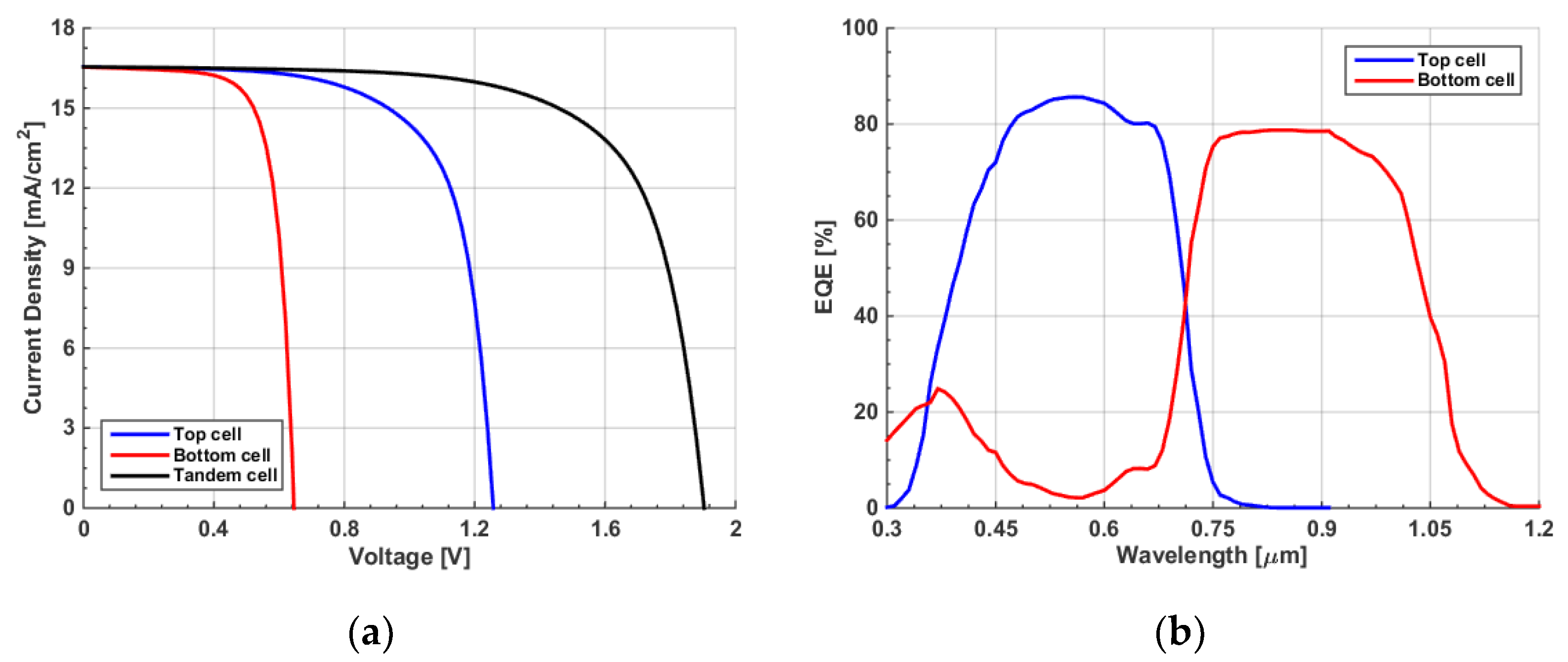
| PV Parameters | Voc (V) | Jsc (mA/cm2) | FF (%) | PCE (%) |
|---|---|---|---|---|
| Top cell | 1.10 | 12.52 | 71.56 | 9.87 |
| Bottom cell | 0.65 | 18.60 | 72.63 | 8.71 |
| Tandem cell | 1.75 | 12.51 | 76.75 | 16.77 |
| Maximum PCE Condition | Current Matching Condition | |||||||
|---|---|---|---|---|---|---|---|---|
| PV Parameters | Voc (V) | Jsc (mA/cm2) | FF (%) | PCE (%) | Voc (V) | Jsc (mA/cm2) | FF (%) | PCE (%) |
| Top cell | 1.26 | 15.70 | 74.99 | 14.82 | 1.26 | 16.55 | 69.37 | 14.43 |
| Bottom cell | 0.65 | 17.21 | 73.28 | 8.15 | 0.65 | 16.55 | 73.37 | 7.83 |
| Tandem cell | 1.91 | 15.74 | 75.80 | 22.73 | 1.90 | 16.55 | 70.46 | 22.19 |
| Top Subcell (Eg (eV)) | Bottom Subcell (Eg (eV)) | Voc (V) | Jsc (mA/cm2) | FF (%) | PCE (%) | Notes | Ref. |
|---|---|---|---|---|---|---|---|
| Perovskite (1.77) | Organic (1.41) | 1.902 | 13.05 | 83.1 | 20.60 | Experimental | [26] |
| Pb-free Perovskite (1.61) | Organic (1.33) | 1.580 | 13.29 | 82.15 | 17.46 | Simulation with SETFOS | [21] |
| Perovskite (1.76) | Perovskite (1.08) | 2.03 | 16.5 | 79.90 | 26.70 | Experimental | [29] |
| Perovskite (1.75) | Perovskite (1.25) | 2.047 | 18.30 | 86.23 | 32.30 | Simulation with SCAPS | [25] |
| Perovskite (1.68) | CIGS (1.10) | 1.77 | 18.8 | 71.2 | 24.20 | Experimental | [29] |
| Perovskite (1.55) | CIGS (1.10) | 1.23 | 28 | 80.71 | 27.74 | Simulation with SCAPS | [48] |
| Polymer (≈1.70) | CIGS (≈1.10) | 1.63 | NA | NA | 14.50 | Experimental | [61] |
| All-Polymer (1.67) | CIGS (1.15) | 1.75 | 12.51 | 76.75 | 16.77 | Simulation with TCAD Silvaco (Initial) | This work |
| All-Polymer (1.67) | CIGS (1.15) | 1.90 | 16.55 | 70.46 | 22.19 | Simulation with TCAD Silvaco (Optimized) | This work |
Disclaimer/Publisher’s Note: The statements, opinions and data contained in all publications are solely those of the individual author(s) and contributor(s) and not of MDPI and/or the editor(s). MDPI and/or the editor(s) disclaim responsibility for any injury to people or property resulting from any ideas, methods, instructions or products referred to in the content. |
© 2023 by the authors. Licensee MDPI, Basel, Switzerland. This article is an open access article distributed under the terms and conditions of the Creative Commons Attribution (CC BY) license (https://creativecommons.org/licenses/by/4.0/).
Share and Cite
Alanazi, T.I.; El Sabbagh, M. Proposal and Design of Flexible All-Polymer/CIGS Tandem Solar Cell. Polymers 2023, 15, 1823. https://doi.org/10.3390/polym15081823
Alanazi TI, El Sabbagh M. Proposal and Design of Flexible All-Polymer/CIGS Tandem Solar Cell. Polymers. 2023; 15(8):1823. https://doi.org/10.3390/polym15081823
Chicago/Turabian StyleAlanazi, Tarek I., and Mona El Sabbagh. 2023. "Proposal and Design of Flexible All-Polymer/CIGS Tandem Solar Cell" Polymers 15, no. 8: 1823. https://doi.org/10.3390/polym15081823