Article

Stable Structure and Fast Ion Diffusion: A Flexible MoO2@Carbon Hollow Nanofiber Film as a Binder-Free Anode for Sodium-Ion Batteries with Superior Kinetics and Excellent Rate Capability

1
State Key Laboratory of Bio-Fibers and Eco-Textiles, Qingdao University, No. 308 Ningxia Road, Qingdao 266071, China
2
College of Materials Science and Engineering, Qingdao University, No. 308 Ningxia Road, Qingdao 266071, China
3
College of Textiles & Clothing, Qingdao University, No. 308 Ningxia Road, Qingdao 266071, China
4
School of Environmental and Municipal Engineering, Qingdao University of Technology, No. 777 Jialingjiang East Road, Qingdao 266520, China
*
Authors to whom correspondence should be addressed.
Polymers 2024, 16(11), 1452; https://doi.org/10.3390/polym16111452
Submission received: 12 April 2024 / Revised: 15 May 2024 / Accepted: 17 May 2024 / Published: 21 May 2024
(This article belongs to the Section Smart and Functional Polymers)

Abstract

:
Designing innovative anode materials that exhibit excellent ion diffusion kinetics, enhanced structural stability, and superior electrical conductivity is imperative for advancing the rapid charge–discharge performance and widespread application of sodium-ion batteries. Hollow-structured materials have received significant attention in electrode design due to their rapid ion diffusion kinetics. Building upon this, we present a high-performance, free-standing MoO2@hollow carbon nanofiber (MoO2@HCNF) electrode, fabricated through facile coaxial electrospinning and subsequent heat treatment. In comparison to MoO2@carbon nanofibers (MoO2@CNFs), the MoO2@HCNF electrode demonstrates superior rate capability, attributed to its larger specific surface area, its higher pseudocapacitance contribution, and the enhanced diffusion kinetics of sodium ions. The discharge capacities of the MoO2@HCNF (MoO2@CNF) electrode at current densities of 0.1, 0.2, 0.5, 1.0, 2.0 and 5.0 A g−1 are 195.55 (155.49), 180.98 (135.20), 163.81 (109.71), 144.05 (90.46), 121.16 (71.21) and 88.90 (44.68) mAh g−1, respectively. Additionally, the diffusion coefficients of sodium ions in the MoO2@HCNFs are 8.74 × 10⁻¹² to 1.37 × 10⁻¹² cm2 s−1, which surpass those of the MoO2@CNFs (6.49 × 10⁻¹² to 9.30 × 10⁻¹³ cm2 s−1) during the discharging process. In addition, these prepared electrode materials exhibit outstanding flexibility, which is crucial to the power storage industry and smart wearable devices.

Graphical Abstract

1. Introduction

The market demand for both power and energy storage batteries has been increasing year after year due to the ongoing growth of the new energy vehicle and energy storage markets, and battery systems have promising growth prospects. However, the development of lithium-ion batteries (LIBs) may be restricted due to the limitations of the raw material reserves [1]. Sodium-ion batteries (SIBs) possess lower material costs, with an abundance of metallic sodium reserves, and have broad research and application prospects [2,3,4]. Meanwhile, SIBs possess a smaller working voltage window than LIBs, making the electrolyte difficult to break down, improving safety and opening up a wide range of research and application possibilities [5]. However, there are several challenges in the study of SIBs. The ionic radius of Na+ (0.113 nm) is around 35% larger than that of Li+ (0.076 nm), resulting in embedding that is difficult to reverse and slow kinetics. The volume change in SIBs is more violent than that of LIBs during the electrochemical reaction, and the slow diffusion kinetics of sodium ions hinders the promotion of its practical application [6,7]. Therefore, it is essential to strengthen the kinetic study of the sodium ion diffusion process.
Ion diffusion kinetics is the basis for storing charges in electrochemical energy storage devices, which is crucial for battery electrochemical reactions and significantly impacts the performance of electrode materials. The main methods to improve the ion diffusion kinetics of electrode materials include morphology control, the use of composites, nanosize applications, etc. [8,9]. Among these methods, morphology control can improve the ion diffusion rate by changing the morphology of the material, such as spherical, rod-like, flake-like, tubular, etc., which can affect the diffusion path and direction of ions [10,11]. In addition, the hollow structure with internal voids not only provides more active sites but also increases the contact area between the electrode and the electrolyte, thus increasing the reaction rate and capacity of the electrode. Meanwhile, it can shorten the ions’ diffusion path and reduce the diffusion resistance, thus improving the ion diffusion rate and the rate performance of the electrode. Furthermore, the hollow structure of the electrode material can greatly relieve the dramatic volume change during electrochemical reactions, which also can strengthen the structural stability of the electrode and cycle life [12,13,14]. Therefore, the construction of hollow-structured anode materials provides an effective strategy for the pursuit of higher performance in energy storage batteries. Zou et al. developed a novel anode material that was prepared for application in LIBs and SIBs. This Ni-MOFs with layered hollow sphere-in-sphere nanostructures had a capacity of 207 mAh g−1 at a current density of 2 A g−1, with a specific capacity attenuation of 0.2% cycles per revolution [15]. Uniform nitrogen–carbon doping on bullet-shaped Cu9S5 hollow particles was performed by Fang et al., exhibiting excellent multiplicity performance and a long cycle life [14]. All of these works encourage the construction of hollow nanostructures to improve ion diffusion kinetics as electrodes for SIBs [16].
At present, the anode materials used for SIBs are mostly carbon-based anode materials (including graphite, amorphous carbon, nanocarbon, etc.), alloy anode materials, metal oxide and sulfur-based anode materials, embedded titanium anode materials, and organic anode materials [17,18]. Among them, carbon-based anode materials have good electrical conductivity but low embedded sodium capacity and poor kinetics [19,20]. Alloy anode materials exhibit high theoretical capacity, but the more drastic volume change leads to lower coulomb efficiency, worse cycling stability, and inferior energy density. Metal oxide anode materials have high theoretical capacity but poor electrical conductivity [9,21]. Embedded titanium anode materials have a small volume change but poor capacity. Organic anode materials have low cost, but poor conductivity and are easily soluble in electrolytes [22,23]. Therefore, it is useful to design metal oxide composite carbon anode materials, which have high specific capacity, high electrical conductivity, and excellent cycling stability. Among many anode materials, molybdenum dioxide (MoO2) is considered a very attractive anode material for batteries, with a vast interlayer distance and high theoretical capacity [24,25]. However, its low conductivity and sluggish diffusion kinetics seriously hinder its application, and most of the current work on MoO2-based anode materials in SIBs focuses on exploring the enhancement of their electrochemical performance without a more in-depth study of their ion diffusion kinetics (Table S1, Supporting Information) [6,26]. Hence, to reveal the intrinsic mechanism of hollow-structured MoO2-based anode materials for enhancing the performance of SIBs, the present work validates the kinetics of the sodium ion diffusion reaction from different perspectives and defines the modulation of the hollow structure as a general strategy.
Herein, we thoroughly investigate the kinetic behavior of the sodium ion diffusion reaction of hollow-structured anode materials compared to solid-structured anode materials in SIBs to design superior anode materials that can greatly improve the electrochemical performance of SIBs. In this work, we constructed a hollow carbon nanofiber film uniformly loaded with MoO2 via coaxial electrospinning and subsequent heat treatment, which was pressed to directly obtain electrode sheets. This method is not only simple and facile to operate, but also eliminates the need for additives and binders, thus reducing the occurrence of side reactions. Additionally, the experimental results verify that the obtained MoO2@HCNF electrode has a larger contact reaction area, a shorter ion diffusion path, more active sites, excellent multiplicity performance, and faster ion diffusion kinetics in sodium-ion batteries compared to those of the MoO2@CNF electrode. Therefore, it is feasible to promote charge transfer and enhance the ion diffusion kinetics by constructing hollow structures.

2. Materials and Methods

2.1. Materials

Polyacrylonitrile (PAN, Mw = 150,000) and polymethylmethacrylate (PMMA, Mw = 35,000) were purchased from Shanghai Macklin Biochemical Co., Ltd., Shanghai, China. Ammonium molybdate tetrahydrate (AMMT) and N, N-dimethylformamide (DMF) were supplied by Sinopharm Chemical Reagent Co., Ltd., Shanghai, China.

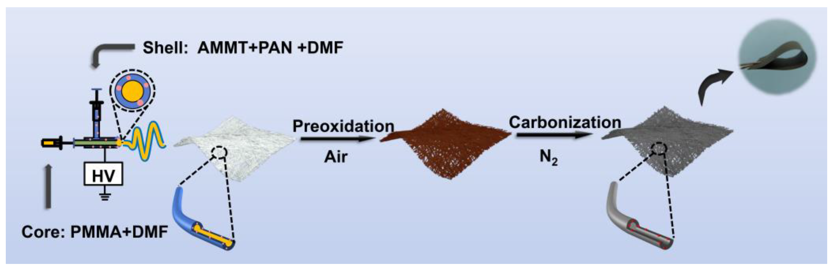
2.2. Synthesis of MoO2@HCNFs and MoO2@CNFs

Firstly, 1.2 g of PAN was dispersed in 8.8 g of DMF and stirred for 4 h at 40 °C to form a pale yellow clarified solution. Subsequently, 0.72 g of AMMT was added and stirred at room temperature overnight, and the final solution formed was named the shell layer solution. Next, 3 g of PMMA was dispersed in 7 g of DMF and stirred overnight at room temperature, and the final solution obtained was named as the core layer solution. Subsequently, the shell layer solution and the core layer solution were transferred into 5 mL syringes and connected to a 17/22-gauge needle for coaxial spinning to obtain the nanofibrous membrane. The working voltage, air humidity, tip-to-collector distance, flow rate of the shell solution, and flow rate of the core solution were fixed at 20 kV, 40%, 18 cm, 0.4 mL h−1, and 0.2 mL h−1, respectively. The nanofibrous membrane was pre-oxidized in a muffle furnace at 270 °C for 2 h at a heating rate of 2 °C min−1 and then moved to a tube furnace and carbonized at 600 °C for 2 h at a heating rate of 3 °C min−1 under nitrogen atmosphere to obtain the MoO2@HCNFs. As a comparison, the MoO2@CNFs were synthesized in the same way as MoO2@HCNFs without the core layer solution.

2.3. Material Characterization

Powder X-ray diffraction (XRD) patterns were recorded on a Rigaku Ultima IV diffractometer (Tokyo, Japan) with Cu Kα (λ = 0.154184 nm) radiation at 40 kV and 40 mA. Field emission scanning electron microscopy (FE-SEM) images were collected on the JEOL JSM-7800F microscope (Tokyo, Japan). High-resolution transmission electron microscope (HRTEM) images and energy dispersive spectroscopy (EDS) mapping were investigated via a JEOL JEM-F200 Plus microscope (Tokyo, Japan). X-ray photoelectron spectroscopy (XPS) spectra were obtained using a ULVAC PHI 5000 Versa Probe Ispectrometer (Chigasaki, Japan) with a monochromatized Al Ka X-ray source (1486.6 eV). Raman spectra were studied using a Horiba LabRAM HR Evolution microscope (Kyoto, Japan) with a wavelength of 532 nm. Thermogravimetric analysis (TGA) was carried out to calculate the active material contents of the samples using METTLER TOLEDO (Zurich, Switzerland) at the heating rate of 10 °C min−1 under an air atmosphere. Nitrogen adsorption–desorption isotherms were examined on a Quantachrome Autosorb-iQ3 (Boynton Beach, FL, USA).

2.4. Electrochemical Measurements

The electrochemical tests were performed using coin-type cells (CR2025), which were assembled in an Ar-filled glove box (H2O < 0.1 ppm, O2 < 0.1 ppm). The as-prepared flexible MoO2@HCNFs and MoO2@CNFs were dried at 80 °C in a vacuum, cut into a disc with a diameter of 14 mm, and used as the cathode electrode directly without any additives. A Na metal foil was used as the counter electrode. The glass microfiber filter (Whatman, grade GF/A) served as the separator. The electrolyte was 1.0 M sodium perchlorate (NaClO4) in ethylene carbonate (EC)/diethyl carbonate (DEC) (1:1 by volume) with 5 wt % fluoroethylene carbonate (FEC). Galvanostatic charge–discharge (GCD) and galvanostatic intermittent titration technique (GITT) tests were tested on the NEWARE battery testing system at room temperature. Cyclic voltammetry (CV) and electrochemical impedance spectroscopy (EIS) tests were performed on an electrochemical workstation (CHI 660E, Shanghai Chenhua, Shanghai, China). The CV curves were performed in the voltage range from 0.01 to 3.00 V (vs. Na/Na+) with different scanning rates. The EIS was measured in the frequency range of 100 kHz–0.01 Hz.

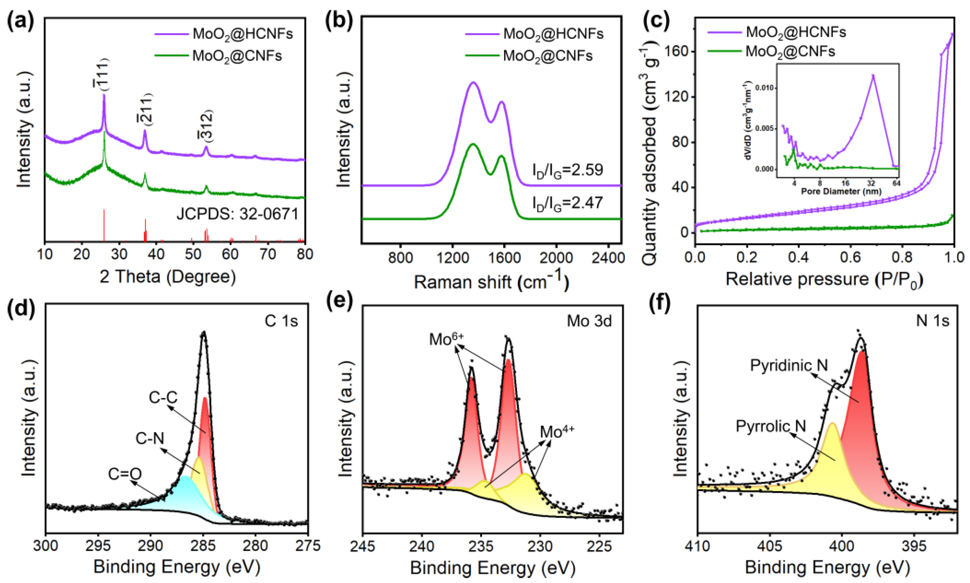
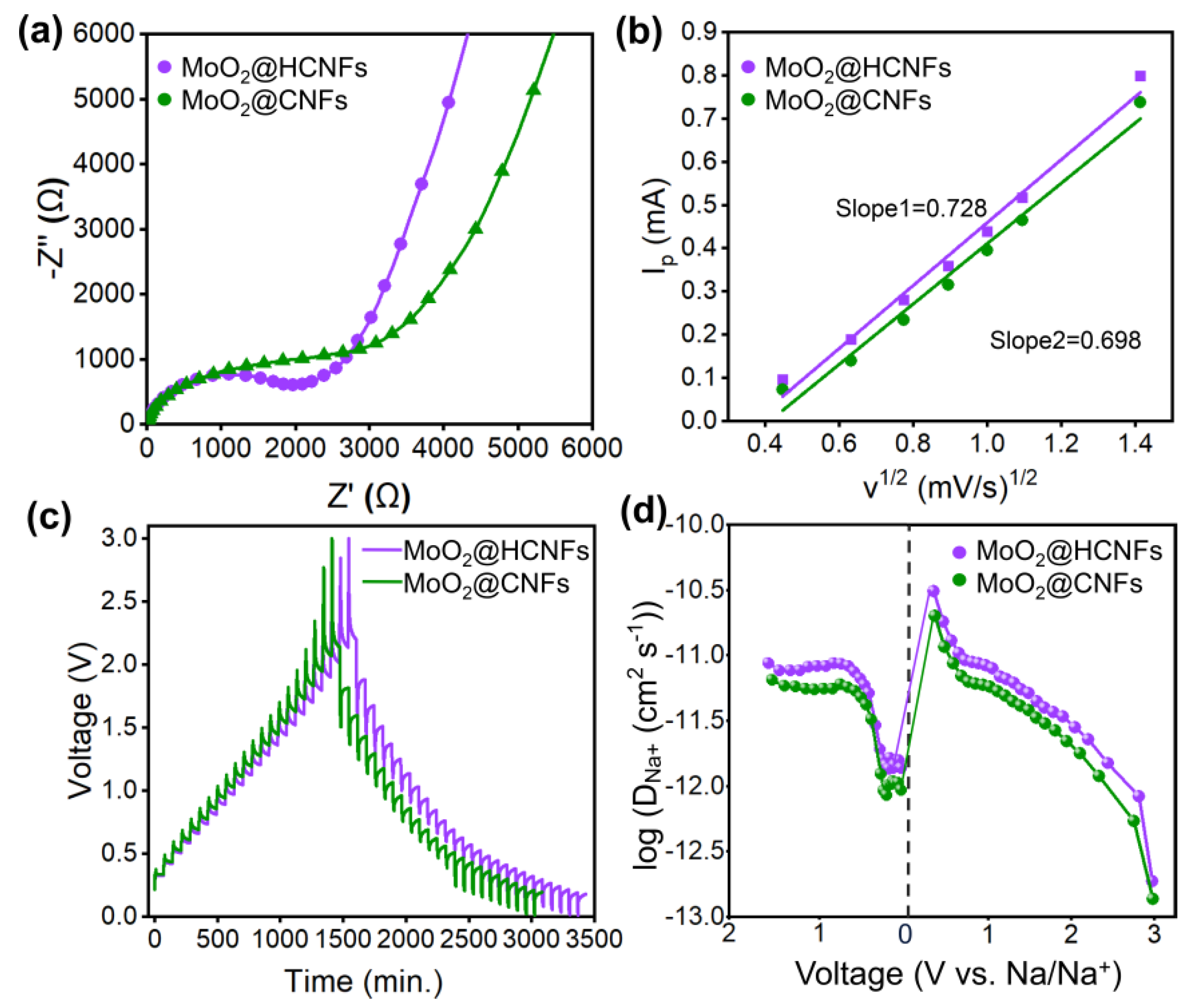
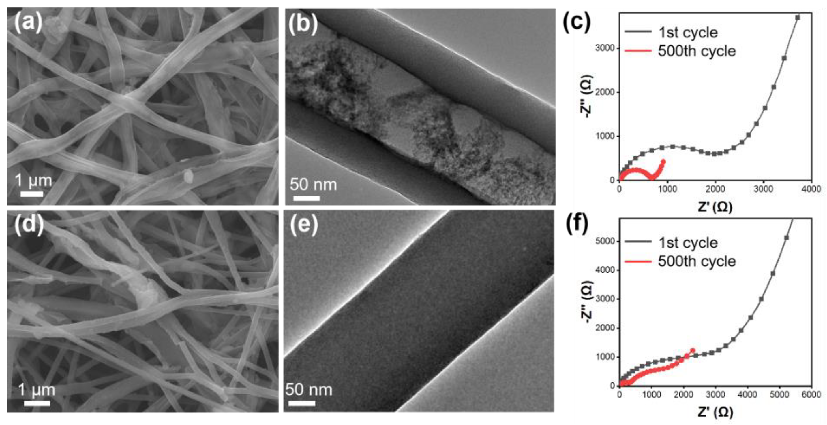
3. Results and Discussion

The synthesis process of MoO2@hollow carbon nanofibers (MoO2@HCNFs) is shown in Figure 1. Firstly, we formed a shell-core fiber structure through a simple coaxial electrospinning method, after pre-oxidation and carbonization under a nitrogen atmosphere at 600 °C. The ammonium molybdate in the shell layer thermally decomposed to form MoO2, while the PMMA in the core layer completely decomposed to form the hollow carbon nanofiber structure. This method of synthesizing carbon nanofibers with a hollow structure is straightforward to operate, and the obtained hollow structure is uniform and smooth, which promotes shortening the transport channel of electrons and ions, accompanied by alleviating volume expansion. Meanwhile, the synthesized carbon nanofiber film can be directly laminated into an electrode sheet without the need for either a conductive agent and binder or an aluminum foil as a collector, reducing the occurrence of side reactions as well as lowering the cost.
Field emission scanning electron microscopy (FE-SEM) and high-resolution transmission electron microscopy (HRTEM) were used to observe the morphologies of the MoO2@HCNFs and MoO2@carbon nanofibers (MoO2@CNFs). The fibers of the MoO2@HCNFs both before (Figure 2a) and after (Figure 2b,c) carbonation were very smooth, with regular and hollow shapes of the fibers. The whole fibrous membranes were mutually supportive and developed a three-dimensional conductive network, similar to that of MoO2@CNFs. In addition, the prepared electrode material exhibits excellent foldability that does not break after 180° bending, which indicates superior flexibility properties (Figure S1, Supporting Information). To distinguish the hollow features between MoO2@HCNFs and MoO2@CNFs, the cross-sectional images are shown in Figure 2c,d. Moreover, the TEM image of MoO2@HCNFs also shows the hollow features of the fibers in more detail in Figure 2e. The MoO2@HCNFs exhibit a hollow feature with thick walls on both sides and thin in the middle, whereas the MoO2@CNFs exhibit a uniform solid feature. The fiber diameters of both the MoO2@HCNFs and the MoO2@CNFs are about 400 nm. The thickness of the hollow carbon wall is around 65 nm. The HRTEM image in Figure 2f demonstrates lattice fringes of 0.136 nm, corresponding to the (−111) plane of the MoO2 (JCPDS: 32-0671), which is consistent with the 26.03° diffraction peak in X-ray diffraction (XRD). Figure 2g shows the element distribution of the MoO2@HCNFs using element mapping technology, exhibiting obvious shell and core layers. The fibers have a clear hollow structure with Mo, O, C, and N elements concentrating on both sides of the fibers, which indicates that MoO2 is dispersed uniformly in the walls of the hollow carbon fibers without agglomeration. The carbon materials can strengthen the electrical conduction of electrode materials, and can also limit the expansion of MoO2 to avoid crystal pulverization and electrode damage caused by excessive stress [27].
The crystal structure and components of the MoO2@HCNFs and MoO2@CNFs were characterized by means of XRD. These diffraction peaks are located at 26.03°, 37.02°, and 53.51°, which are indexed to the (−111), (−211) and (−312) crystal planes of MoO2 (JCPDS: 32-0671), respectively (Figure 3a) [28]. Furthermore, in Figure 3b, the Raman spectra of the MoO2@HCNFs and MoO2@CNFs exhibit two obvious bands located at 1358 cm−1 and 1582 cm−1, which are attributed to the D-band and G-band, respectively [29,30]. The calculated ID/IG ratio of the MoO2@HCNFs is 2.59, which is higher than that of the MoO2@CNFs (2.47), suggesting that more active sites and abundant defects were formed in the hollow structure. Furthermore, both the specific surface area and pore size greatly affect the electrochemical properties of electrode materials, and thus the nitrogen adsorption–desorption isotherms and pore size distribution curves of the MoO2@HCNFs and MoO2@CNFs are shown in Figure 3c. Both the MoO2@HCNFs and MoO2@CNFs exhibit reversible type IV isotherms, which are mesoporous materials. According to the Brunauer–Emmett–Teller (BET) model, the specific surface area of MoO2@HCNFs (46.98 m2 g−1) is significantly higher than that of the MoO2@CNFs (7.87 m2 g−1), which demonstrates that the electrode material has a larger reaction contact area with the electrolyte in MoO2@HCNFs. Both MoO2@HCNFs and MoO2@CNFs have abundant mesoporous structures, and the pore size of MoO2@HCNFs is concentrated at around 32 nm, which is larger than that of MoO2@CNFs at around 4 nm, which may be more favorable for the rapid diffusion of ions and accelerate the electrochemical reaction kinetics. Therefore, a uniformly loaded MoO2 carbon nanofiber film with simple synthesis and excellent hollow structure was successfully prepared and directly pressed as an electrode sheet without the need for conductive agents and additives in this work. Moreover, according to the thermal gravimetric analysis (TGA, Figure S2, Supporting Information), the MoO2@HCNF and MoO2@CNF film started to lose weight rapidly after 350 °C, corresponding to the oxidation of carbon in the samples. Meanwhile, the residual MoO3 may be generated by the oxidation of MoO2 with weight retention of 37.9% and 40.9%, respectively. Based on these data, the MoO2 content of the MoO2@HCNFs and MoO2@CNFs was calculated to be 33.69% and 36.35%, respectively [28,31].
The surface elemental chemical states of electrode materials were tested by means of X-ray photoelectron spectroscopy (XPS). The full survey spectrum (Figure S3, Supporting Information) indicates that the MoO2@HCNFs are composed of Mo, C, N, and O elements. The peaks of the C 1s (Figure 3d) are divided into three peaks located at 284.80 eV, 285.36 eV, and 286.63 eV, assigned to C-C, C-N, and C=O bonds, respectively [28,32,33]. The peaks of Mo 3d could be divided to four components (Figure 3e), including two peaks located at 231.19 eV and 234.66 eV of Mo4+ and two peaks located at 232.64 eV and 235.81 eV of Mo6+ [28,31]. The presence of Mo6+ could be assigned to the oxidation of MoO2. The signal of N 1s could be clearly distinguished as two peaks with binding energies of 398.55 eV and 400.60 eV (Figure 3f), corresponding to pyridinic nitrogen and pyrrolic nitrogen, respectively, further confirming the presence of nitrogen. The spectrum of O 1s in Figure S3b corresponds to the lattice oxygen of MoO2 at the peak at 531.89 eV and shows oxygen-containing functional groups at 533.00 eV [30,34]. Meanwhile, nitrogen-doped carbon materials can introduce multiple defects, which correspondingly result in more active reaction sites and also improve electrical conductivity.
The electrochemical measurements of the MoO2@HCNF and MoO2@CNF electrode materials were tested by assembling CR2025-type coin cells. Figure 4a displays the cyclic voltammetry (CV) curves of the MoO2@HCNFs in the voltage range from 0.01 to 3.0 V at a scan rate of 0.2 mV s−1. During the first curve, the reduction peaks were observed at 1.1 V and 0.4 V, corresponding to the formation of a solid electrolyte interphase (SEI) in the initial discharge cycle and the irreversible reactions [31,35]. There are no obvious oxidation peaks during the process of anodic scanning. After the activation of the first scan, a reduction peak located at 0.47 V and an oxidation peak located at 0.34 V were observed in subsequent scans, which are related to the conversion reaction between MoO2 and Mo. Furthermore, the CV curves were highly overlapped after the second cycle, showing high cycling stability and reflecting the strong reversibility of the composite electrode’s charging and discharging. The composite electrode shows excellent electrochemical activity, which proves the effectiveness and importance of the carbon nanofiber conductive network [28,31,36]. Figure 4b displays the charging and discharging curves of the hollow composite anode material for the 1st, 2nd, 10th, 50th, and 100th cycles. During the first discharge, a long voltage plateau started to appear at around 1.20 V, which corresponds to a reduction peak in the CV curve and finally reaches a high specific capacity of 347.14 mAh g−1. This voltage plateau disappeared in the subsequent cycles, and the specific discharge capacity decreased, representing the irreversible decomposition of the electrolyte and forming SEI. The later charge–discharge curves almost overlapped, indicating that the conversion reaction was highly reversible and MoO2 obtained good electrochemical stability in the composite electrode. Further, the cycling performance of the MoO2@HCNF and MoO2@CNF electrodes were investigated at 0.2 A g−1. The MoO2@HCNF electrode delivered excellent cycling stability with a reversible specific capacity of 221.55 mAh g−1 with 63.82% initial coulombic efficiency (ICE) after 500 cycles (Figure 4c). Notably, the MoO2@CNF electrode showed an inferior reversible specific capacity of 163.90 mAh g−1 after 500 cycles. To further explore the electrochemical performance of the MoO2@HCNF electrode, the rate capability is shown in Figure 4d. The MoO2@HCNF (or MoO2@CNF) electrode delivered high discharge capacities of 195.55 (155.49), 180.98 (135.20), 163.81 (109.71), 144.05 (90.46), 121.16 (71.21) and 88.90 (44.68) mAh g−1 at current densities of 0.1, 0.2, 0.5, 1.0, 2.0 and 5.0 A g−1, respectively. This could be restored to 222.08 (171.09) mAh g−1 when the current density was restored to 0.1 A g−1, which indicates that the MoO2@HCNF electrode has excellent multiplication performance. To further investigate the cycling stability, the MoO2@HCNF electrode was tested at a high current density of 5 A g−1 after ultra-long cycling (Figure 4e). After 1000 cycles, the discharge capacity of MoO2@HCNF electrodes increased from the initial 110.46 mAh g−1 to 174.10 mAh g−1, which could be attributed to the continuous activation of the electrode materials during the cycling process. At the beginning of the cycle, the permeability of the electrolyte is not good, and Na+ cannot diffuse into the electrode material quickly, so the sodium storage capacity is low at the beginning of the cycle. As the cycle proceeds, the electrolyte gradually penetrates into the interior of the electrode material, and the advantage of the utilization of the hollow structure increases significantly, so the specific capacity increases gradually. In contrast, the discharge capacity of the MoO2@CNF electrode was poorer, with an initial capacity of 47.42 mAh g−1 at a high current density and 57.02 mAh g−1 after 1000 cycles, which was much lower than that of the MoO2@HCNF electrode. The higher capacity of the MoO2@HCNF electrode compared with the MoO2@CNF electrode can be attributed to the more active sites provided by the hollow structure, which is favorable for the contact and reaction between MoO2 and electrolyte in the electrode. At the same time, the buffer space provided by the hollow carbon wall can work with the carbon layer to buffer the volume expansion of MoO2 and maintain the structural stability and cycling stability of the composite.
To investigate the reaction kinetics of the MoO2@HCNFs and MoO2@CNFs, CV tests were performed at different scan rates from 0.2 mV s−1 to 2.0 mV s−1. The position of the redox peaks was only slightly shifted when the scan rate increased from 0.2 mV s−1 to 2.0 mV s−1, which shows superior cycling stability and reversible performance (Figure 5a,d). The relationship between the peak current (i) and the scan rate (v) can be described by Equations (1) and (2): [36,37]
i = avb
log (i) = blog (v) + log (a)
where a and b are variable constants. The b value is the slope of the plots of log (i) versus log (v). When the b value is close to 0.5, the electrochemical behavior is mainly a diffusion-controlled process, while the b value is approaching 1.0, which represents a capacitive-controlled process. The b values of MoO2@HCNFs (or MoO2@CNFs) were 0.870 (0.837) and 0.922 (0.987) for the cathodic and anodic peaks, respectively (Figure 5b,e). This confirms that the electrochemical behaviors of the MoO2@HCNFs and MoO2@CNFs are represented by the predominance of the surface capacitive controlled process. To further investigate the pseudocapacitive contribution, Equations (3) and (4) are given [38,39]:
i = k1v + k2v1/2
i/v1/2 = k1v1/2 + k2
where k1v is the surface capacitive behaviour and k2v1/2 is the diffusion-controlled behaviour. As shown in Figure 5c, the pseudocapacitance contribution of the MoO2@HCNFs is 75.0% at a scan rate of 1.0 mV s−1, indicating that the pseudocapacitance behavior accounts for a higher proportion of the overall capacitance. Furthermore, we calculated the pseudocapacitance contribution of the MoO2@HCNFs and MoO2@CNFs at different scan rates (Figure 5f). The surface capacitive proportion gradually increased as the scan rate increased, with values of 61.9%, 67.8%, 70.1%, 73.0%, 75.0%, 77.5%, and 85.4% at gradually increasing sweep speeds of 0.2, 0.4, 0.6, 0.8, 1.0, 1.2, and 2.0 mV s−1, respectively. In comparison, the MoO2@CNFs exhibit a capacitance share of 59.5%, 63.5%, 67.7%, 72.4%, 75.6%, 77.6%, and 83.9%, respectively. In addition, the MoO2@HCNFs have a higher pseudocapacitance contribution than MoO2@CNFs at scan rates of 0.2, 0.4, 0.6, 0.8, and 2.0 mV s−1. The higher pseudocapacitance contribution facilitates the fast transfer kinetics of Na+ during intercalation/extraction, thereby further enhancing the rate performance of the MoO2@HCNF electrode. Therefore, the MoO2@HCNFs exhibited stronger surface reaction dynamics based on calculations, showing that they possessed a higher pseudocapacitance contribution than the MoO2@CNFs. This suggests that the hollow channels constructed by the MoO2@HCNFs are crucial for the transport of sodium ions in the electrodes.
To further investigate the Na+ diffusion kinetics of the MoO2@HCNFs and MoO2@CNFs, electrochemical impedance spectroscopy (EIS) and the galvanostatic intermittent titration technique (GITT) were measured. The Nyquist plots shown in Figure 6a consist of a semicircle in the high-medium frequency region and a sloping line in the low-frequency region, with the semicircle region relating to the SEI film resistance (Re) and charge transfer resistance (Rct) and the sloping line corresponding to the Warburg impendence (Zw) of ion diffusion [39,40,41]. The MoO2@HCNF electrode exhibited a smaller Rct than that of the MoO2@CNFs before cycling. This shows that the MoO2@HCNF electrode is capable of faster charge transfer and ion diffusion, demonstrating its excellent rate performance. Furthermore, the diffusion coefficient can also be calculated using the Randles–Sevcik equation [37,42]:
Ip = 2.69 × 10⁵An3/2CD1/2v1/2
where Ip corresponds to the peak current, A corresponds to the surface area of the electrode, n corresponds to the electron transfer number, C corresponds to the concentration of sodium ions, v corresponds to the scan rate, and D corresponds to the diffusion coefficient of sodium ions. As shown in Figure 6b, the slope of the line reflects the value of the Na+ diffusion coefficient. MoO2@HCNFs exhibits higher Na+ diffusion coefficients and is more beneficial to the transport of Na+ due to its steeper line. In addition, the diffusion behavior of Na+ is further investigated by the GITT curve, showing that the MoO2@HCNFs exhibited a longer time and higher diffusion coefficient of sodium ions during charging and discharging (Figure 6c,d). The Na+ diffusion coefficient (DNa+) could be calculated by Equation (6).
D N a + = 4 π τ [ ( m B V m A M B ) Δ E s Δ E t ] 2
where τ is the constant current titration time; A is the surface area of the electrode; mB, Vm, and MB are the mass, molar volume, and molar mass of active materials, respectively; and ΔEs and ΔEt are the total voltage change due to pulses and the voltage change for constant current charging/discharging, respectively. The diffusion coefficients of Na+ in MoO2@HCNFs calculated via GITT tests during discharging and charging were 8.74 × 10⁻¹² to 1.37 × 10⁻¹² cm2 s−1 and 3.09 × 10⁻¹¹ to 1.87 × 10⁻¹³ cm2 s−1, while the diffusion coefficients of Na+ in the MoO2@CNFs were 6.49 × 10⁻¹² to 9.30 × 10⁻¹³ cm2 s−1 and 2.01 × 10⁻¹¹ to 1.36 × 10⁻¹³ cm2 s−1, respectively. These results suggest that hollow channels of the MoO2@HCNFs provide faster transport velocity of sodium ions, resulting in superior ion diffusion kinetics.
The micromorphology and diffusion kinetics of the MoO2@HCNFs and MoO2@CNF electrodes were further investigated after 500 cycles at 0.2 A g−1 of SIBs. The integrity of the hollow carbon nanofiber structure in MoO2@HCNFs is remarkable, as it exhibited no signs of swelling or collapse after cycling. The overall morphology of the fibers closely resembled their pre-cycling state, with only minimal fiber breaks observed. Similarly, MoO2@CNFs experienced some fiber breaks and agglomerations between fibers (Figure 7a–e). The structure of the electrode material after 500 cycles of charging and discharging was not destroyed, indicating that the prepared hollow structure can provide a buffer space for the volume change in the electrochemical reaction process, and avoids the problem of structural collapse of the material during multiple charging and discharging cycles. This demonstrates the robustness of the hollow structure obtained from the preparation in this work, which is important for the long cycling performance of the electrode materials. In addition, the charge transfer resistance of both the MoO2@HCNFs and MoO2@CNFs decreased after 500 cycles, which is favorable for improving electrochemical performance (Figure 7c,f).

4. Conclusions

In summary, a high-performance free-standing MoO2@HCNF electrode was fabricated by means of facile coaxial electrospinning and subsequent heat treatment. It is revealed that the MoO2@HCNFs not only possessed a larger specific surface area and superior specific capacity but also delivered better rate capability and faster diffusion kinetics of Na+. The superior electrochemical performance may be related to the following advantages: (i) The larger specific surface area can provide more active sites, and MoO2 is uniformly loaded on the carbon nanofibers. At the same time, the 3D carbon network also increases the contact area between the electrode material and the electrolyte and provides more electronic channels. (ii) The ultra-long and excellent cycling performance is assigned to the hollow carbon nanofiber structure, which alleviates the volume change during charging and discharging while shortening the Na+ diffusion path and improving electron conductivity, leading to stronger ion transport and ultimately improved sodium storage performance. This work not only provides a simple and widely applicable strategy for the fabrication and utilization of electrode materials for high-performance energy storage batteries; the properties of the flexible film are also conducive to research on smart wearable devices.

Supplementary Materials

The following supporting information can be downloaded at: https://www.mdpi.com/article/10.3390/polym16111452/s1, Figure S1. SEM images of (a) as−spun MoO2@CNFs and (b) MoO2@CNFs; (c) flexibility test of MoO2@HCNFs film; Figure S2. TGA curves of MoO2@HCNFs and MoO2@CNFs; Figure S3. (a) Survey XPS spectra of the MoO2@HCNFs and (b) high-resolution XPS spectra of O 1s; Table S1. Comparison of sodium storage performance of MoO2−based anode materials [43,44,45].

Author Contributions

Software, M.G.; Formal analysis, N.F. and M.G.; Data curation, N.F.; Writing—original draft, N.F.; Writing—review & editing, N.F.; Supervision, J.Z., C.G. and B.L.; Project administration, J.Z., C.G., Y.Z. and B.L.; Funding acquisition, Y.Z. All authors have read and agreed to the published version of the manuscript.

Funding

This research was funded by the Natural Science Foundation of Shandong Province (ZR2023MB145), the Natural Science Foundation of Qingdao (23-2-1-242-zyyd-jch) and the Youth Innovation Team Project of Shandong Provincial Education Department.

Institutional Review Board Statement

Not applicable.

Data Availability Statement

The data that support the findings of this study are available in the Supplementary Materials of this article.

Acknowledgments

We would like to thank all authors for their valuable contributions to this research. Specifically, we appreciate the thorough formal analysis conducted by N.F. and M.G. We are also deeply grateful to J.Z., C.G., and B.L. for their supervision, providing guidance and direction throughout the project. Lastly, we thank Y.Z. for securing the funding that has enabled this research to be conducted. We are immensely grateful to all authors for their dedication, hard work, and collaboration, and we are proud to have published this manuscript with their collective contributions.

Conflicts of Interest

The authors declare no conflicts of interest.

References

  1. Shi, C.; Yu, M. Flexible solid-state lithium-sulfur batteries based on structural designs. Energy Storage Mater. 2023, 57, 429–459. [Google Scholar] [CrossRef]
  2. Zhao, X.-X.; Fu, W.; Zhang, H.-X.; Guo, J.-Z.; Gu, Z.-Y.; Wang, X.-T.; Yang, J.-L.; Lü, H.-Y.; Wu, X.-L.; Ang, E.H. Pearl-structure-enhanced NASICON cathode toward ultrastable sodium-ion batteries. Adv. Sci. 2023, 10, 2301308. [Google Scholar] [CrossRef] [PubMed]
  3. Xu, H.; Li, H.; Wang, X. The anode materials for lithium-ion and sodium-ion batteries based on conversion reactions: A review. ChemElectroChem 2023, 10, e202201151. [Google Scholar] [CrossRef]
  4. Vaalma, C.; Buchholz, D.; Weil, M.; Passerini, S. A cost and resource analysis of sodium-ion batteries. Nat. Rev. Mater. 2018, 3, 18013. [Google Scholar] [CrossRef]
  5. Kundu, D.; Talaie, E.; Duffort, V.; Nazar, L.F. The emerging chemistry of sodium ion batteries for electrochemical energy storage. Angew. Chem. Int. Ed. 2015, 54, 3431–3448. [Google Scholar] [CrossRef] [PubMed]
  6. Wang, T.; Su, D.; Shanmukaraj, D.; Rojo, T.; Armand, M.; Wang, G. Electrode materials for sodium-ion batteries: Considerations on crystal structures and sodium storage mechanisms. Electrochem. Energy Rev. 2018, 1, 200–237. [Google Scholar] [CrossRef]
  7. Delmas, C. Sodium and sodium-ion batteries: 50 years of research. Adv. Energy Mater. 2018, 8, 1703137. [Google Scholar] [CrossRef]
  8. Qiao, S.; Zhou, Q.; Ma, M.; Liu, H.K.; Dou, S.X.; Chong, S. Advanced anode materials for rechargeable sodium-ion batteries. ACS Nano 2023, 17, 11220–11252. [Google Scholar] [CrossRef] [PubMed]
  9. Prajapati, A.K.; Bhatnagar, A. A review on anode materials for lithium/sodium-ion batteries. J. Energy Chem. 2023, 83, 509–540. [Google Scholar] [CrossRef]
  10. Yang, C.; Ou, X.; Xiong, X.; Zheng, F.; Hu, R.; Chen, Y.; Liu, M.; Huang, K. V5S8-graphite hybrid nanosheets as a high rate-capacity and stable anode material for sodium-ion batteries. Energy Environ. Sci. 2017, 10, 107–113. [Google Scholar] [CrossRef]
  11. Chao, D.; Zhu, C.; Yang, P.; Xia, X.; Liu, J.; Wang, J.; Fan, X.; Savilov, S.V.; Lin, J.; Fan, H.J.; et al. Array of nanosheets render ultrafast and high-capacity Na-ion storage by tunable pseudocapacitance. Nat. Commun. 2016, 7, 12122. [Google Scholar] [CrossRef] [PubMed]
  12. Tang, L.-B.; Zhang, B.; Peng, T.; He, Z.-J.; Yan, C.; Mao, J.; Dai, K.; Wu, X.-W.; Zheng, J.-C. MoS2/SnS@C hollow hierarchical nanotubes as superior performance anode for sodium-ion batteries. Nano Energy 2021, 90, 106568. [Google Scholar] [CrossRef]
  13. Lian, X.; Xu, N.; Ma, Y.; Hu, F.; Wei, H.; Chen, H.-Y.; Wu, Y.; Li, L.; Li, D.; Peng, S. In-situ formation of Co1−xS hollow polyhedrons anchored on multichannel carbon nanofibers as self-supporting anode for lithium/sodium-ion batteries. Chem. Eng. J. 2021, 421, 127755. [Google Scholar] [CrossRef]
  14. Fang, Y.; Yu, X.-Y.; Lou, X.W. Bullet-like Cu9S5 hollow particles coated with nitrogen-doped carbon for sodium-ion batteries. Angew. Chem. Int. Ed. 2019, 58, 7744–7748. [Google Scholar] [CrossRef] [PubMed]
  15. Zou, F.; Chen, Y.-M.; Liu, K.; Yu, Z.; Liang, W.; Bhaway, S.M.; Gao, M.; Zhu, Y. Metal organic frameworks derived hierarchical hollow NiO/Ni/graphene composites for lithium and sodium storage. ACS Nano 2016, 10, 377–386. [Google Scholar] [CrossRef]
  16. Yu, L.; Hu, H.; Wu, H.B.; Lou, X.W. Complex hollow nanostructures: Synthesis and energy-related applications. Adv. Mater. 2017, 29, 1604563. [Google Scholar] [CrossRef]
  17. Bai, X.; Wu, N.; Yu, G.; Li, T. Recent advances in anode materials for sodium-ion batteries. Inorganics 2023, 11, 289. [Google Scholar] [CrossRef]
  18. Rojo, T.; Hu, Y.-S.; Forsyth, M.; Li, X. Sodium-ion batteries. Adv. Energy Mater. 2018, 8, 1800880. [Google Scholar] [CrossRef]
  19. Jia, M.; Zhang, L.; Yuan, Q. Application of new COF materials in secondary battery anode materials. Molecules 2023, 28, 5953. [Google Scholar] [CrossRef]
  20. Zhang, T.; Li, C.; Wang, F.; Noori, A.; Mousavi, M.F.; Xia, X.; Zhang, Y. Recent advances in carbon anodes for sodium-ion batteries. Chem. Rec. 2022, 22, e202200083. [Google Scholar] [CrossRef]
  21. Tian, Y.; An, Y.; Zhang, B. Approaching microsized alloy anodes via solid electrolyte interphase design for advanced rechargeable batteries. Adv. Energy Mater. 2023, 13, 2300123. [Google Scholar] [CrossRef]
  22. Yao, S.; Ramakrishna, S.; Chen, G. Recent advances in metal-organic frameworks based on electrospinning for energy storage. Adv. Fiber Mater. 2023, 5, 1592–1617. [Google Scholar] [CrossRef]
  23. Tan, S.; Yang, H.; Zhang, Z.; Xu, X.; Xu, Y.; Zhou, J.; Zhou, X.; Pan, Z.; Rao, X.; Gu, Y.; et al. The progress of hard carbon as an anode material in sodium-ion batteries. Molecules 2023, 28, 3134. [Google Scholar] [CrossRef] [PubMed]
  24. He, H.; Man, Y.; Yang, J.; Xie, J.; Xu, M. MoO2 nanosheets embedded in amorphous carbon matrix for sodium-ion batteries. R. Soc. Open Sci. 2017, 4, 170892. [Google Scholar] [CrossRef] [PubMed]
  25. Chen, Z.; Yang, T.; Shi, H.; Wang, T.; Zhang, M.; Cao, G. Single nozzle electrospinning synthesized MoO2@C core shell nanofibers with high capacity and long-term stability for lithium-ion storage. Adv. Mater. Interfaces 2017, 4, 1600816. [Google Scholar] [CrossRef]
  26. Yabuuchi, N.; Kubota, K.; Dahbi, M.; Komaba, S. Research development on sodium-ion batteries. Chem. Rev. 2014, 114, 11636–11682. [Google Scholar] [CrossRef] [PubMed]
  27. Ebner, M.; Marone, F.; Stampanoni, M.; Wood, V. Visualization and quantification of electrochemical and mechanical degradation in li ion batteries. Science 2013, 342, 716–720. [Google Scholar] [CrossRef]
  28. Zhang, H.; Han, Z.; Li, X.; Kong, F.; Tao, S.; Qian, B. MoO2 nanosheets embedded into carbon nanofibers with a self-standing structure for lithium ion and sodium ion batteries. Ceram. Int. 2021, 47, 26839–26846. [Google Scholar] [CrossRef]
  29. Ramakrishnan, K.; Nithya, C.; Karvembu, R. High-performance sodium ion capacitor based on MoO2@rGO nanocomposite and goat hair derived carbon electrodes. ACS Appl. Energy Mater. 2018, 1, 841–850. [Google Scholar] [CrossRef]
  30. Li, L.; Chen, Z.; Zhang, H.; Zhu, Z.; Zhang, M. The double effects of sulfur-doping on MoO2/C nanofibers with high properties for Na-ion batteries. Appl. Surf. Sci. 2018, 455, 343–348. [Google Scholar] [CrossRef]
  31. Liang, J.; Gao, X.; Guo, J.; Chen, C.; Fan, K.; Ma, J. Electrospun MoO2@NC nanofibers with excellent Li+/Na+ storage for dual applications. Sci. China Mater. 2018, 61, 30–38. [Google Scholar] [CrossRef]
  32. Wang, X.; Han, Y.; Li, W.; Li, J.; Ren, S.; Wang, M.; Han, G.; Yu, J.; Zhang, Y.; Zhao, H. Doped carbon dots enable highly efficient multiple-color room temperature phosphorescence. Adv. Opt. Mater. 2023, 12, 2301962. [Google Scholar] [CrossRef]
  33. Meng, X.; Song, Y.; Jing, Q.; Zhao, H. Self-precipitation of highly purified red emitting carbon dots as red phosphors. J. Phys. Chem. Lett. 2023, 14, 9176–9182. [Google Scholar] [CrossRef] [PubMed]
  34. Geng, Q.; Su, X.; Dong, F.; Wang, Z. Two-phase Solvothermal Synthesis of MoO2/RGO Nanocomposites for Lithium-Ion Battery Anodes. In Proceedings of the IOP Conference Series: Earth and Environmental Science, Changsha, China, 3 February 2021. [Google Scholar]
  35. Huang, J.; Xu, Z.; Cao, L.; Zhang, Q.; Ouyang, H.; Li, J. Tailoring MoO2/graphene oxide nanostructures for stable, high-density sodium-ion battery anodes. Energy Technol. 2015, 3, 1108–1114. [Google Scholar] [CrossRef]
  36. Zhao, C.; Yu, C.; Zhang, M.; Huang, H.; Li, S.; Han, X.; Liu, Z.; Yang, J.; Xiao, W.; Liang, J.; et al. Ultrafine MoO2-carbon microstructures enable ultralong-life power-type sodium ion storage by enhanced pseudocapacitance. Adv. Energy Mater. 2017, 7, 1602880. [Google Scholar] [CrossRef]
  37. Li, X.; Han, Z.; Yang, W.; Li, Q.; Li, H.; Xu, J.; Li, H.; Liu, B.; Zhao, H.; Li, S.; et al. 3D ordered porous hybrid of ZnSe/N-doped carbon with anomalously high Na+ mobility and ultrathin solid electrolyte interphase for sodium-ion batteries. Adv. Funct. Mater. 2021, 31, 2106194. [Google Scholar] [CrossRef]
  38. Yin, J.; Hai, P.; Gao, Y.; Gan, Z.; Wu, C.; Cheng, Y.; Xu, X. Theory-driven designed TiO2@MoO2 heterojunction: Balanced crystallinity and nanostructure toward desirable kinetics and high-rate sodium-ion storage. Nano Res. 2023, 16, 4941–4949. [Google Scholar] [CrossRef]
  39. Tao, W.; Chen, J.; Xu, C.; Liu, S.; Fakudze, S.; Wang, J.; Wang, C. Nanostructured MoS2 with interlayer controllably regulated by ionic liquids/cellulose for high-capacity and durable sodium storage properties. Small 2023, 19, 2207397. [Google Scholar] [CrossRef]
  40. Zhu, Y.; Ren, J.; Huang, G.; Dong, C.-L.; Huang, Y.-C.; Lu, P.; Tang, H.; Liu, Y.; Shen, S.; Yang, D. Red phosphorus grafted high-index (116) faceted anatase TiO2 for Z-scheme photocatalytic pure water splitting. Adv. Funct. Mater. 2023, 34, 2311623. [Google Scholar] [CrossRef]
  41. Zeng, F.; Liu, H.; Pan, Y.; Yu, M.; Qu, Y.; Yuan, C. Encapsulating N-doped carbon nanorod bundles/MoO2 nanoparticles via surface growth of ultrathin MoS2 nanosheets for ultrafast and ultralong cycling sodium storage. ACS Appl. Mater. Interfaces 2020, 12, 6205–6216. [Google Scholar] [CrossRef]
  42. Ni, X.P.; Chen, H.F.; Liu, C.L.; Zeng, F.L.; Yu, H.Y.; Ju, A.Q. A freestanding nitrogen-doped carbon nanofiber/MoS2 nanoflowers with expanded interlayer for long cycle-life lithium-ion batteries. J. Alloys Compd. 2020, 818, 152835. [Google Scholar] [CrossRef]
  43. Jiang, J.; Yang, W.; Wang, H.; Zhao, Y.; Guo, J.; Zhao, J.; Beidaghi, M.; Gao, L. Electrochemical performances of MoO2/C nanocomposite for sodium ion storage: An insight into rate dependent charge/discharge mechanism. Electrochim. Acta 2017, 240, 379–387. [Google Scholar] [CrossRef]
  44. Zhao, X.; Zhao, Y.D.; Yang, Y.; Liu, Z.H.; Wang, H.E.; Sui, J.H.; Cai, W. Fresh MoO2 as a better electrode for pseudocapacitive sodium-ion storage. New J. Chem. 2018, 42, 14721–14724. [Google Scholar] [CrossRef]
  45. Luo, Y.; Ding, X.; Ma, X.; Liu, D.; Fu, H.; Xiong, X. Constructing MoO2@MoS2 heterostructures anchored on graphene nanosheets as a high-performance anode for sodium ion batteries. Electrochim. Acta 2021, 388, 138612. [Google Scholar] [CrossRef]
Figure 1. Schematic illustration of the synthetic process of MoO2@HCNF composites via the electrospinning method.
Polymers 16 01452 g001
Figure 2. (ac) SEM images of the MoO2@HCNFs (inserted: photograph of flexible MoO2@HCNFs film); (d) SEM image of the MoO2@CNFs; (e) FETEM image of the MoO2@HCNFs; (f) HRTEM image of the MoO2@HCNFs; (g) high−angle annular dark−field (HAADF) image and corresponding elemental mapping images of the MoO2@HCNFs.
Polymers 16 01452 g002
Figure 3. (a) XRD patterns of the MoO2@HCNFs and MoO2@CNFs; (b) Raman spectra of the MoO2@HCNFs and MoO2@CNFs; (c) nitrogen adsorption−desorption isotherm curves of the MoO2@HCNFs and MoO2@CNFs (inserted: pore size distribution curves); high−resolution XPS spectra of the MoO2@HCNFs: (d) C 1s, (e) Mo 3d, and (f) N 1s.
Polymers 16 01452 g003
Figure 4. (a) CV curves of the MoO2@HCNF electrode at the scan rate of 0.2 mV s−1 for SIBs; (b) galvanostatic charge/discharge curves of the MoO2@HCNFs at 0.2 A g−1 for SIBs; (c) cycle performance, (d) rate performance, and (e) long cycle performance of the MoO2@HCNFs and MoO2@CNFs for SIBs.
Polymers 16 01452 g004
Figure 5. (a) CV curves of the MoO2@HCNFs at different scan rates; (b) corresponding log(i) versus log(ν) linear relationships at peaks; (c) pseudocapacitive contribution of the MoO2@HCNFs at scan rates of 1.0 mV s−1; (d) CV curves of MoO2@CNFs at different scan rates; (e) corresponding log(i) versus log(ν) linear relationships at peaks; (f) pseudocapacitive contribution of the MoO2@HCNFs and MoO2@CNFs at different scan rates.
Polymers 16 01452 g005
Figure 6. (a) Nyquist plots, (b) linear relationships between the peak current Ip and v1/2 of MoO2@HCNFs and MoO2@CNFs; (c) GITT tests; and (d) calculated sodium−ion diffusion coefficients of MoO2@HCNFs and MoO2@CNFs.
Polymers 16 01452 g006
Figure 7. (a) SEM images, (b) TEM images, and (c) Nyquist plots of MoO2@HCNFs; (d) SEM images, (e) TEM images, and (f) Nyquist plots of MoO2@CNFs after 500 cycles at 0.2 A g−1 for SIBs.
Polymers 16 01452 g007
Disclaimer/Publisher’s Note: The statements, opinions and data contained in all publications are solely those of the individual author(s) and contributor(s) and not of MDPI and/or the editor(s). MDPI and/or the editor(s) disclaim responsibility for any injury to people or property resulting from any ideas, methods, instructions or products referred to in the content.

