
Epoxy/Graphene Nanoplatelet (GNP) Nanocomposites: An Experimental Study on Tensile, Compressive, and Thermal Properties


Abstract
:
1. Introduction
2. Materials and Methods
2.1. Materials
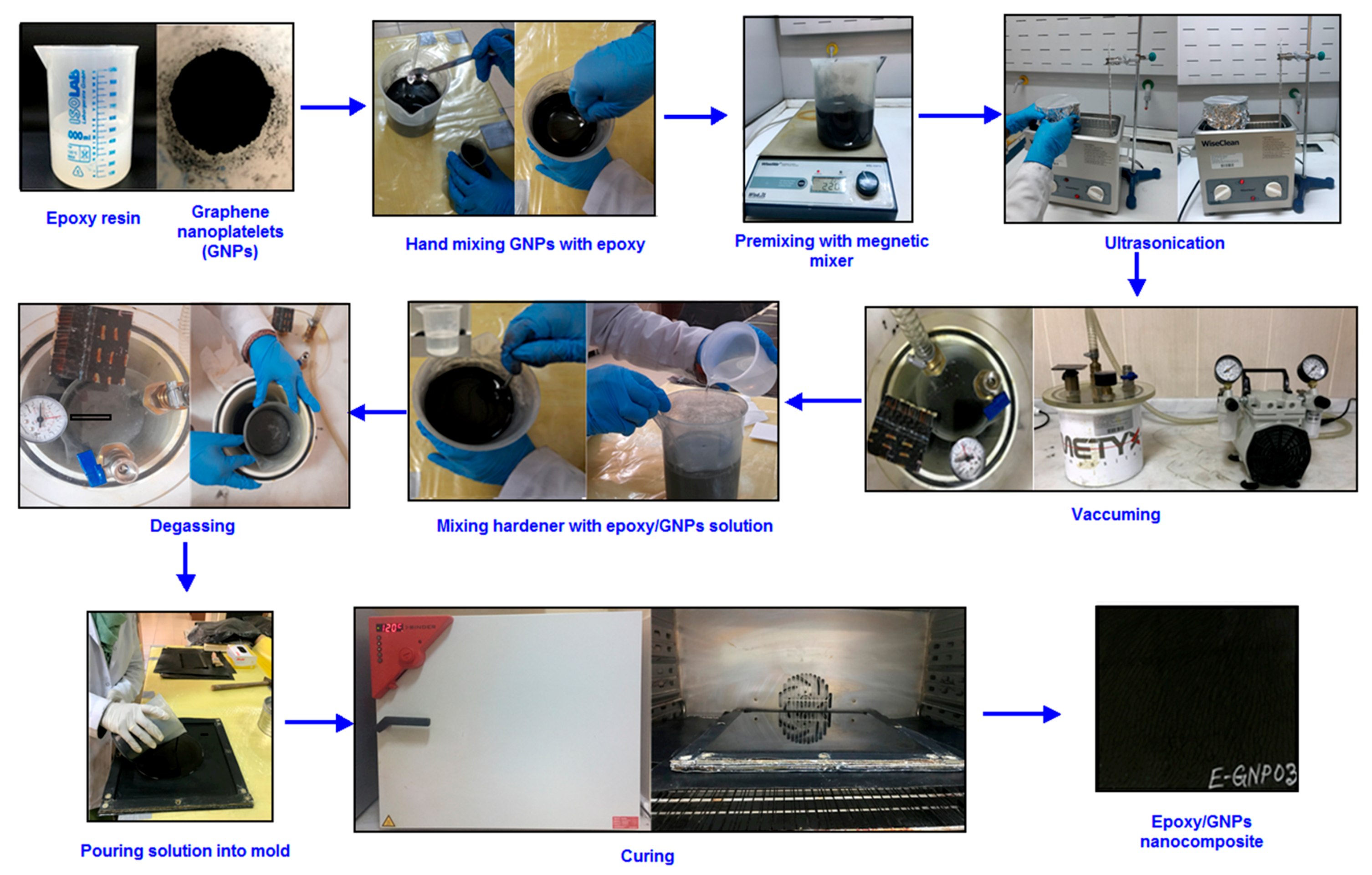
2.2. Preparation of Epoxy Composite
2.3. Preparation of Epoxy/Graphene Nanoplatelet Composite
2.4. Composite Testing
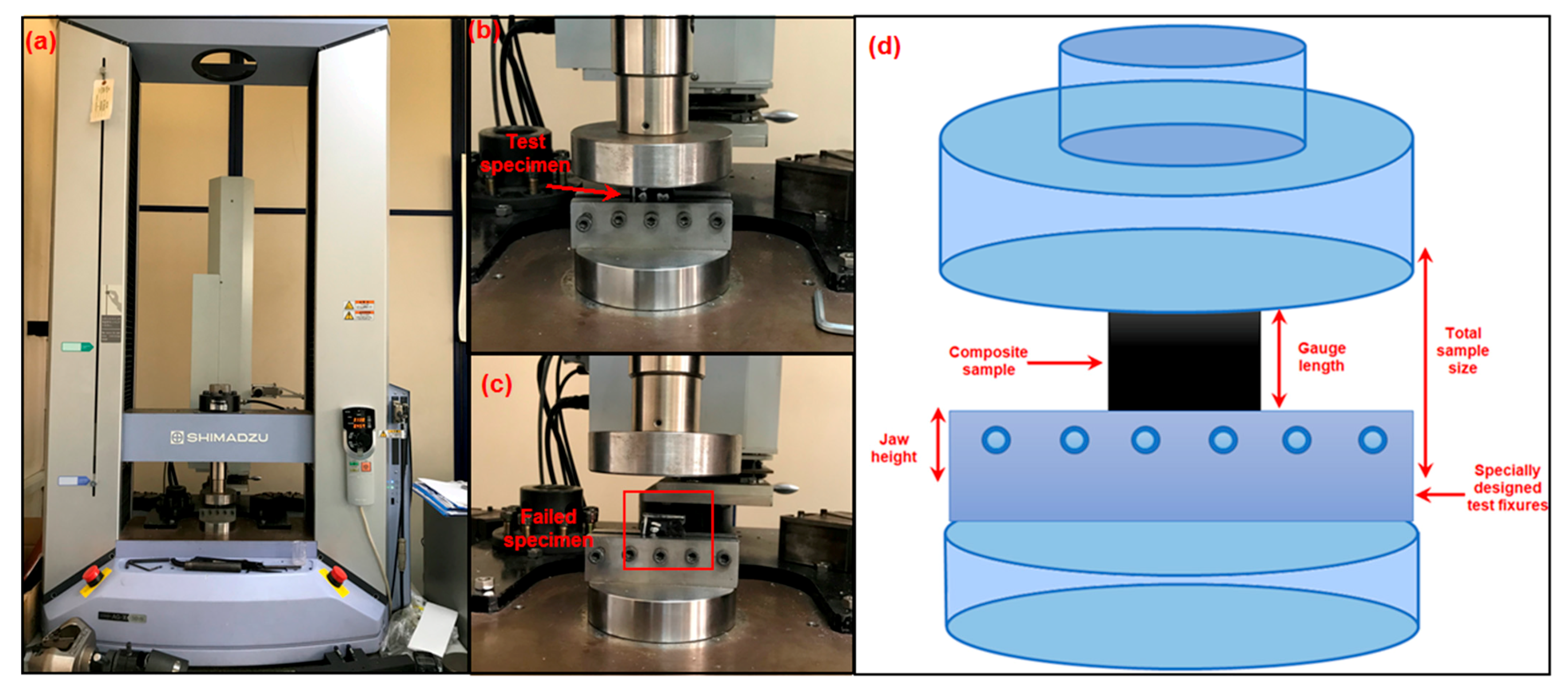
2.4.1. Tensile Test
2.4.2. Compression Test
2.4.3. Thermal Conductivity Test
2.5. Analysis and Characterizations
3. Results and Discussion
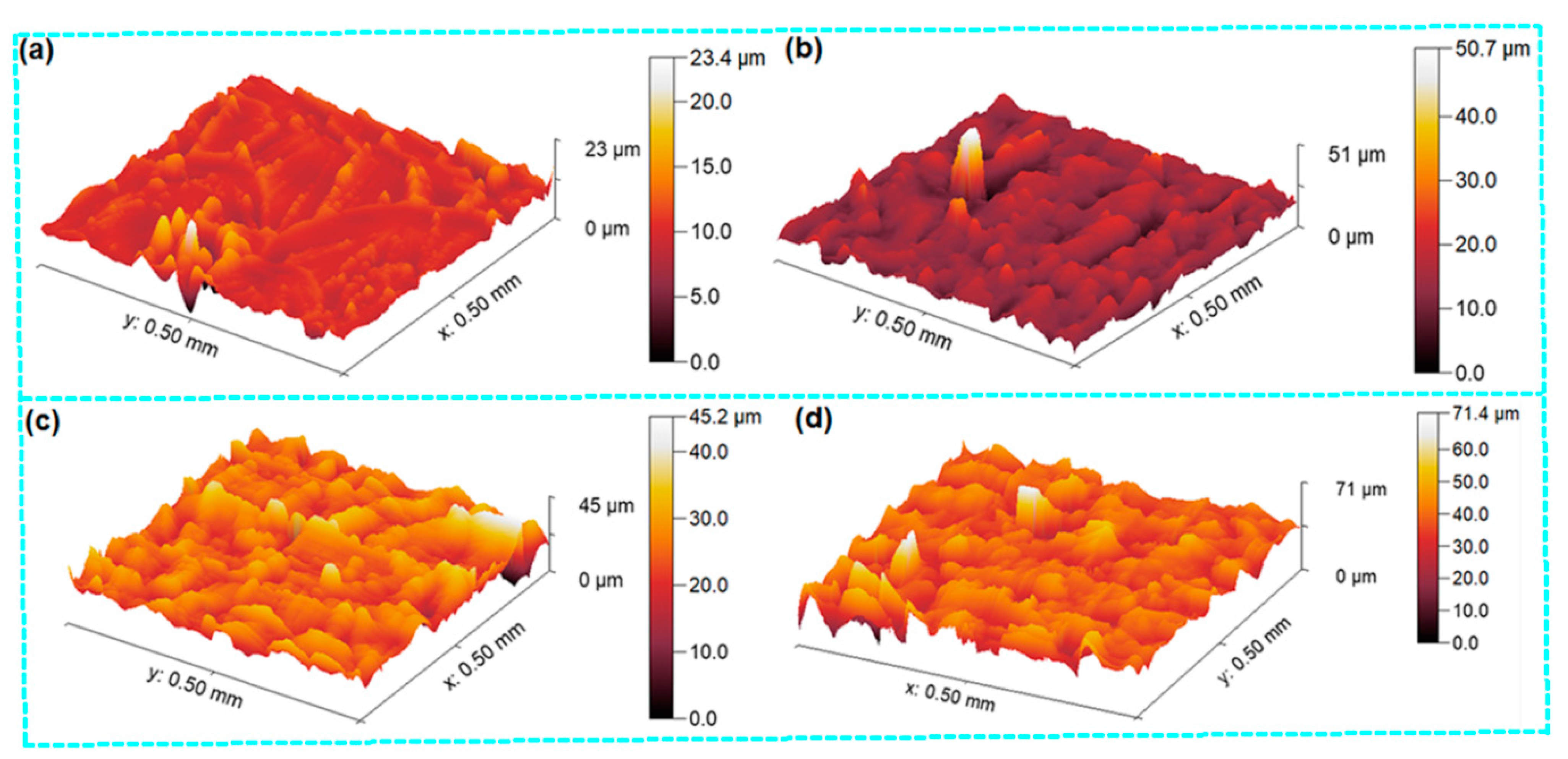
3.1. Surface Morphology and Structure
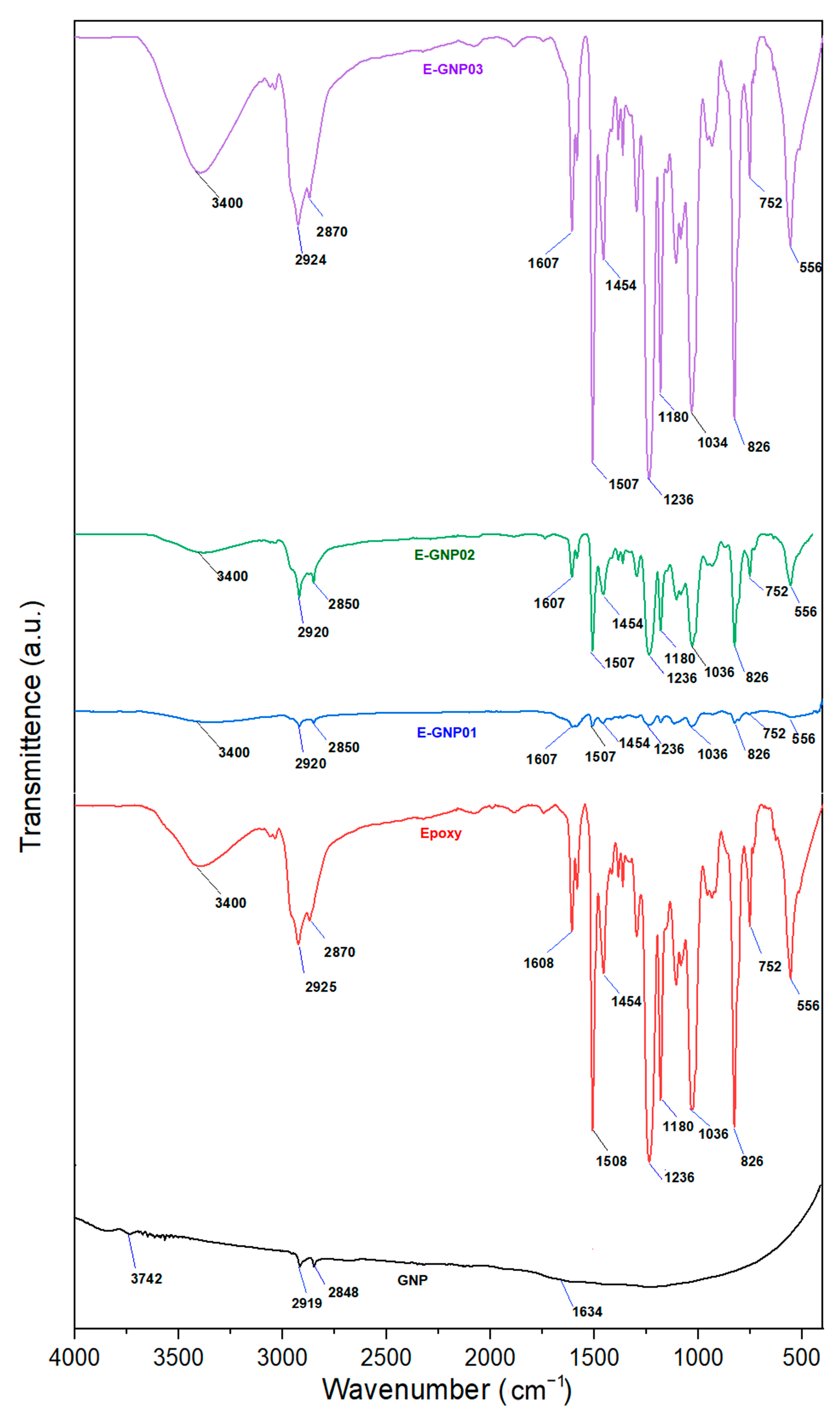
3.1.1. FTIR Spectroscopy Result
3.1.2. Raman Spectroscopy Result
3.2. Mechanical Properties
3.2.1. Density of Nanocomposites
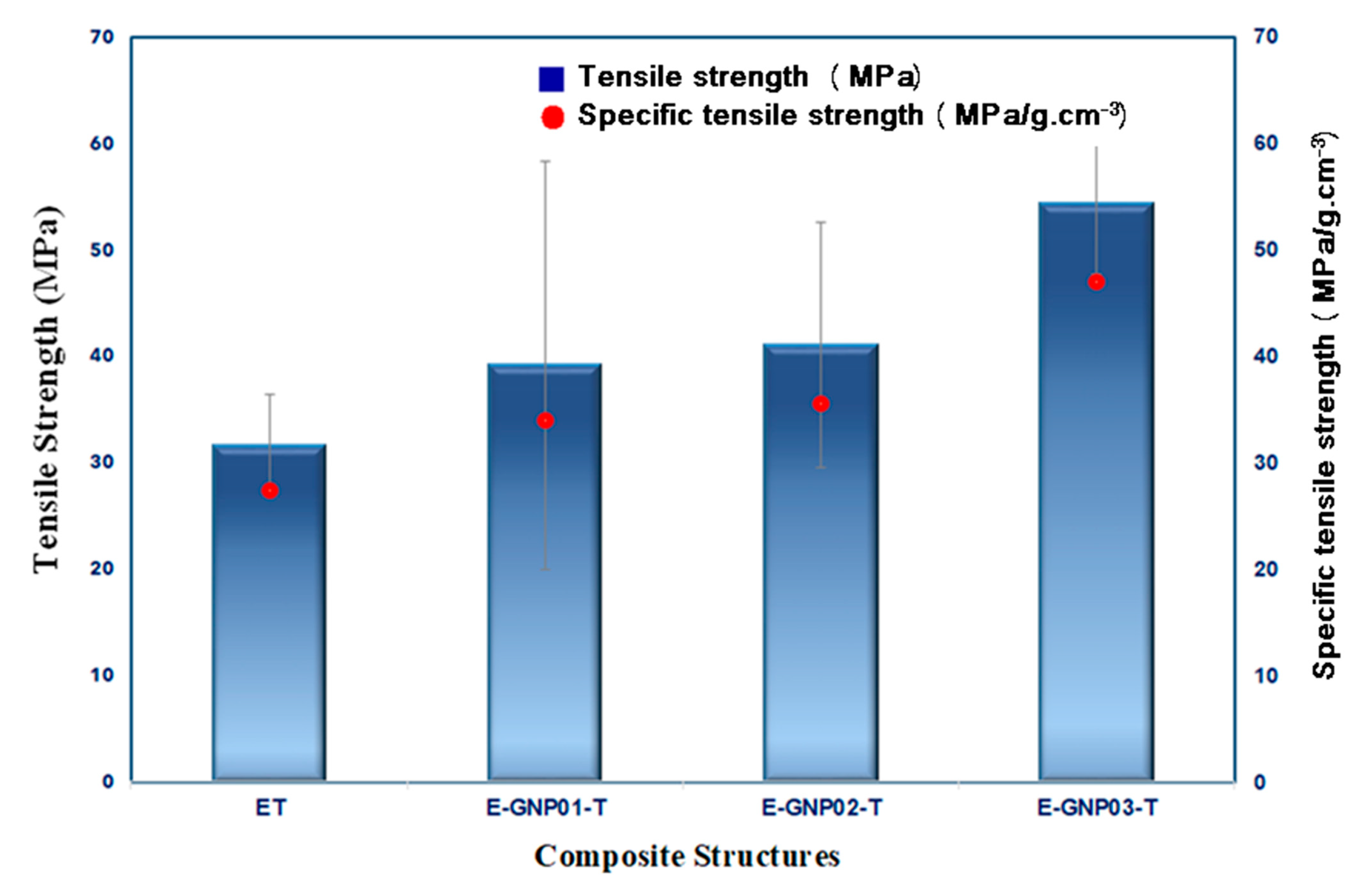
3.2.2. Tensile Properties
Tensile Strength
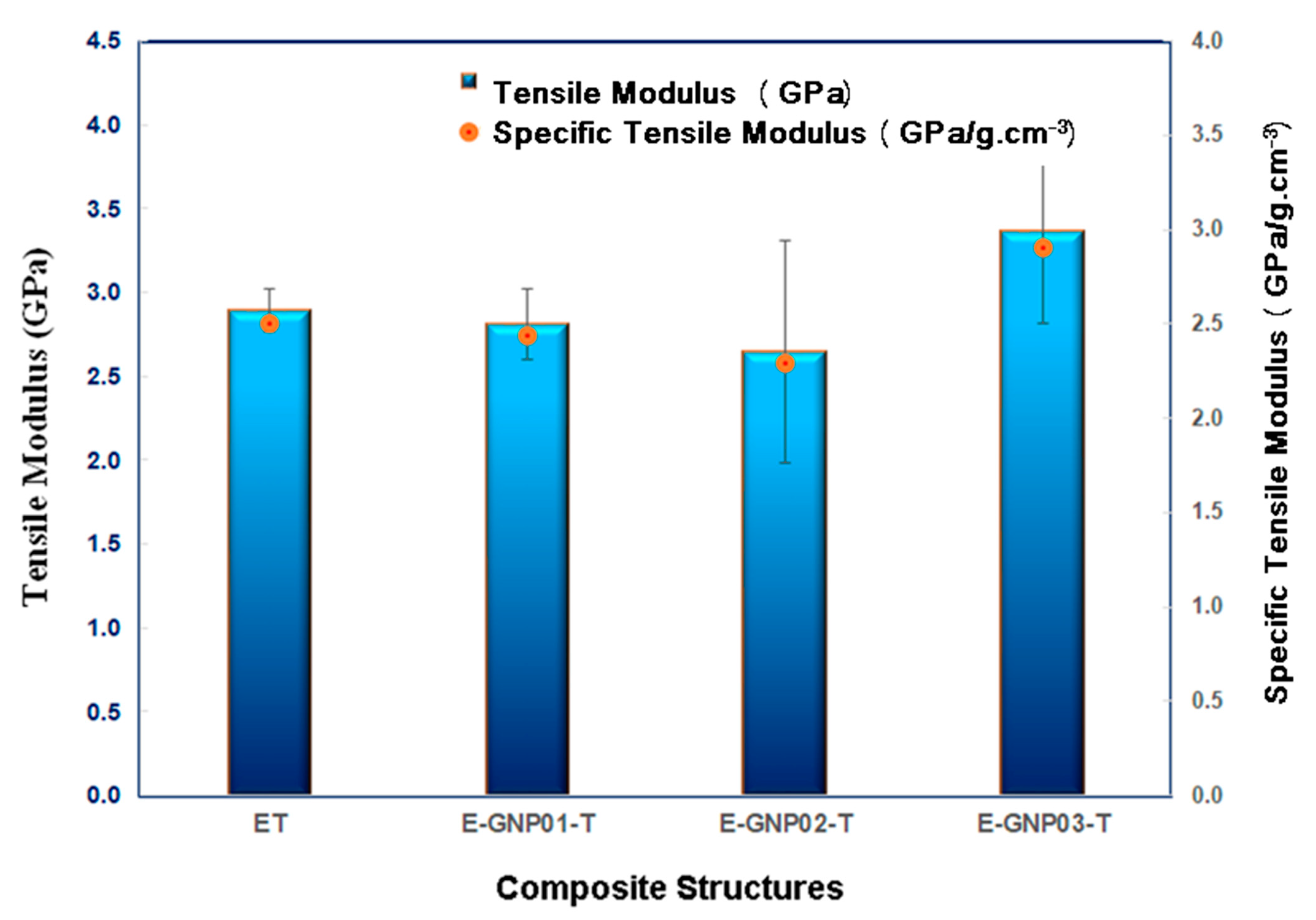
Tensile Modulus
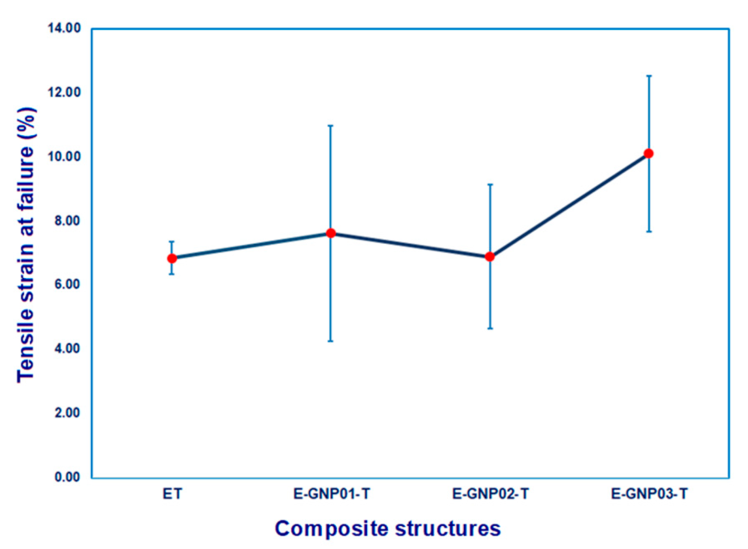
Tensile Strain
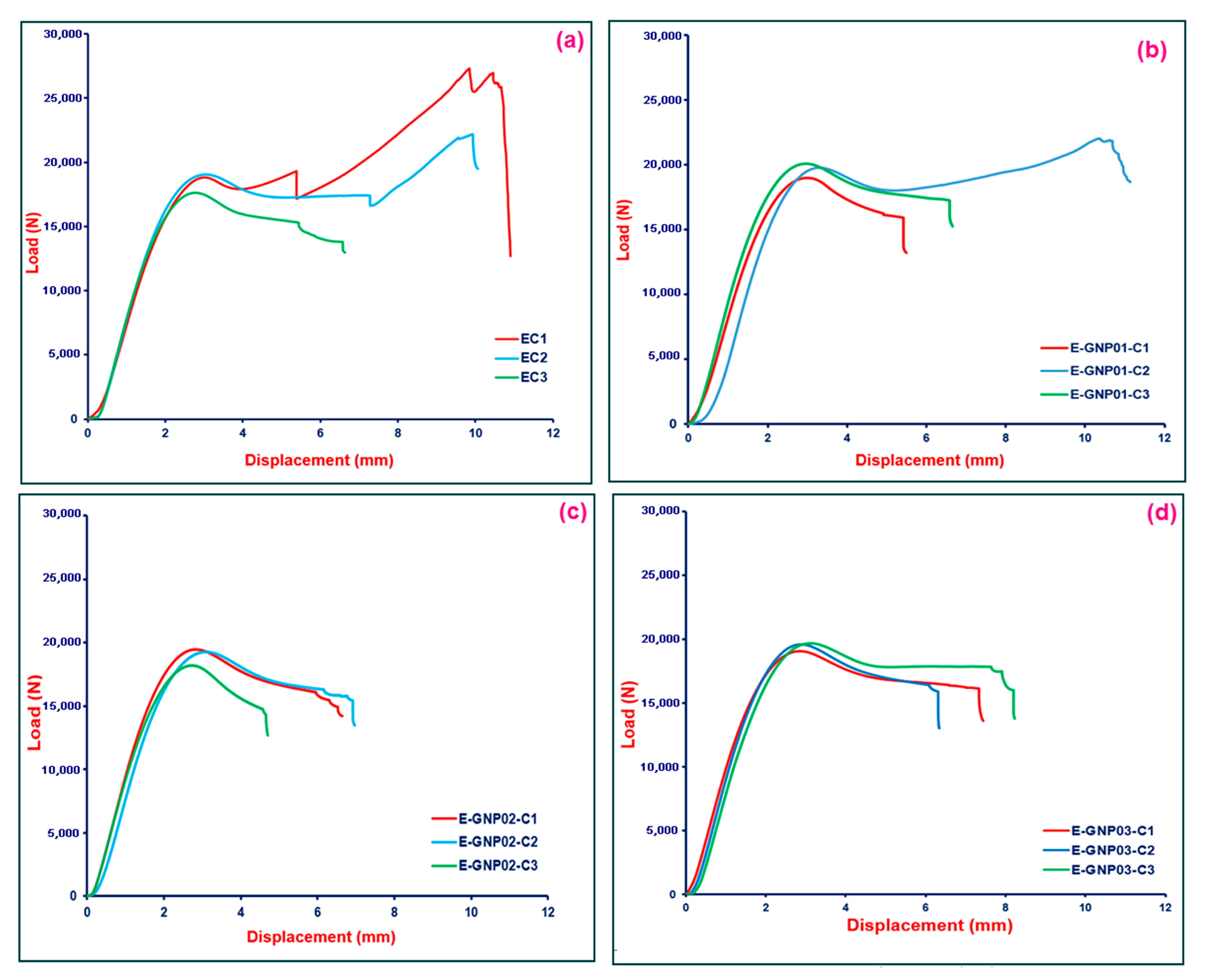
3.2.3. Compressive Properties
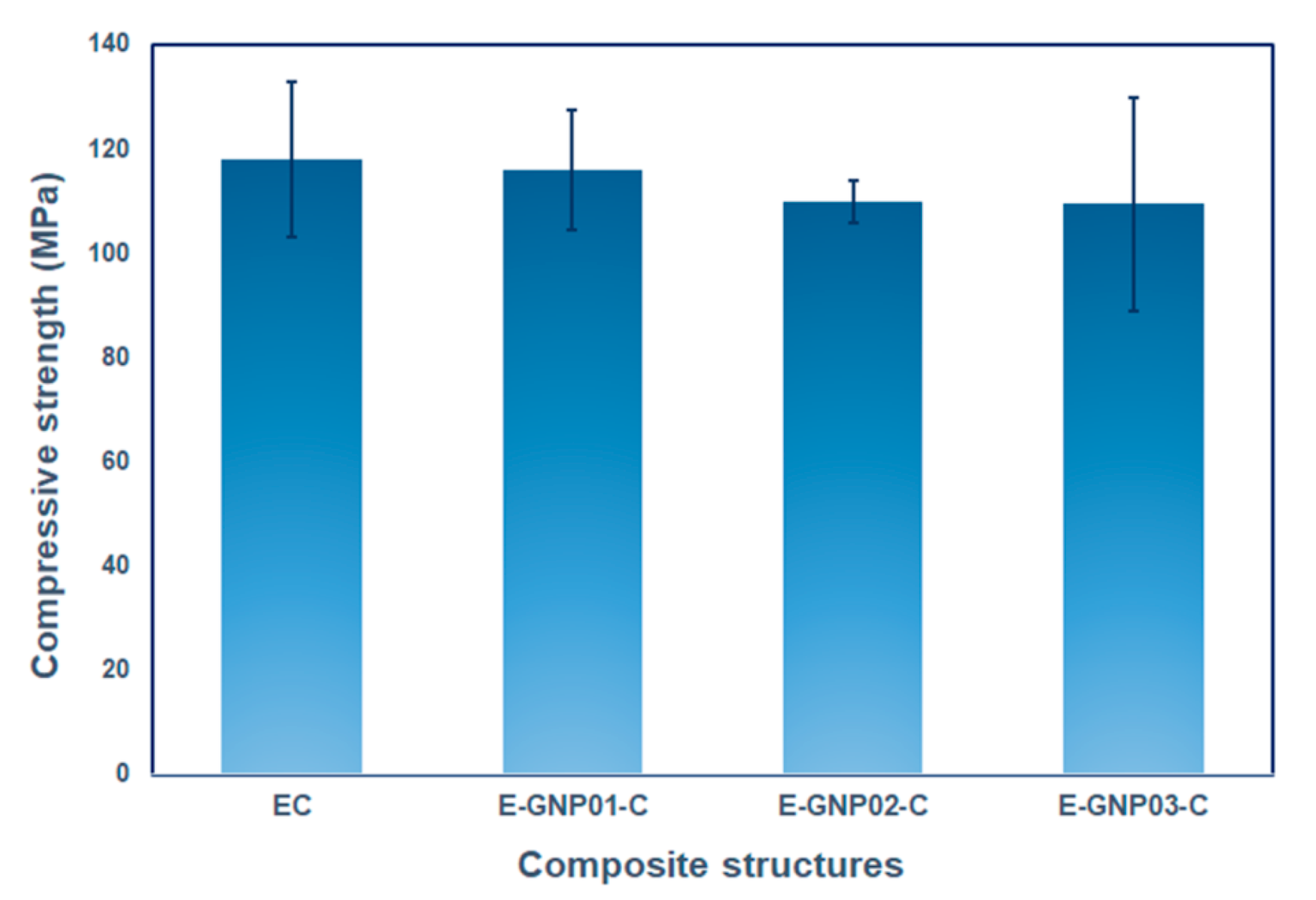
Compressive Strength
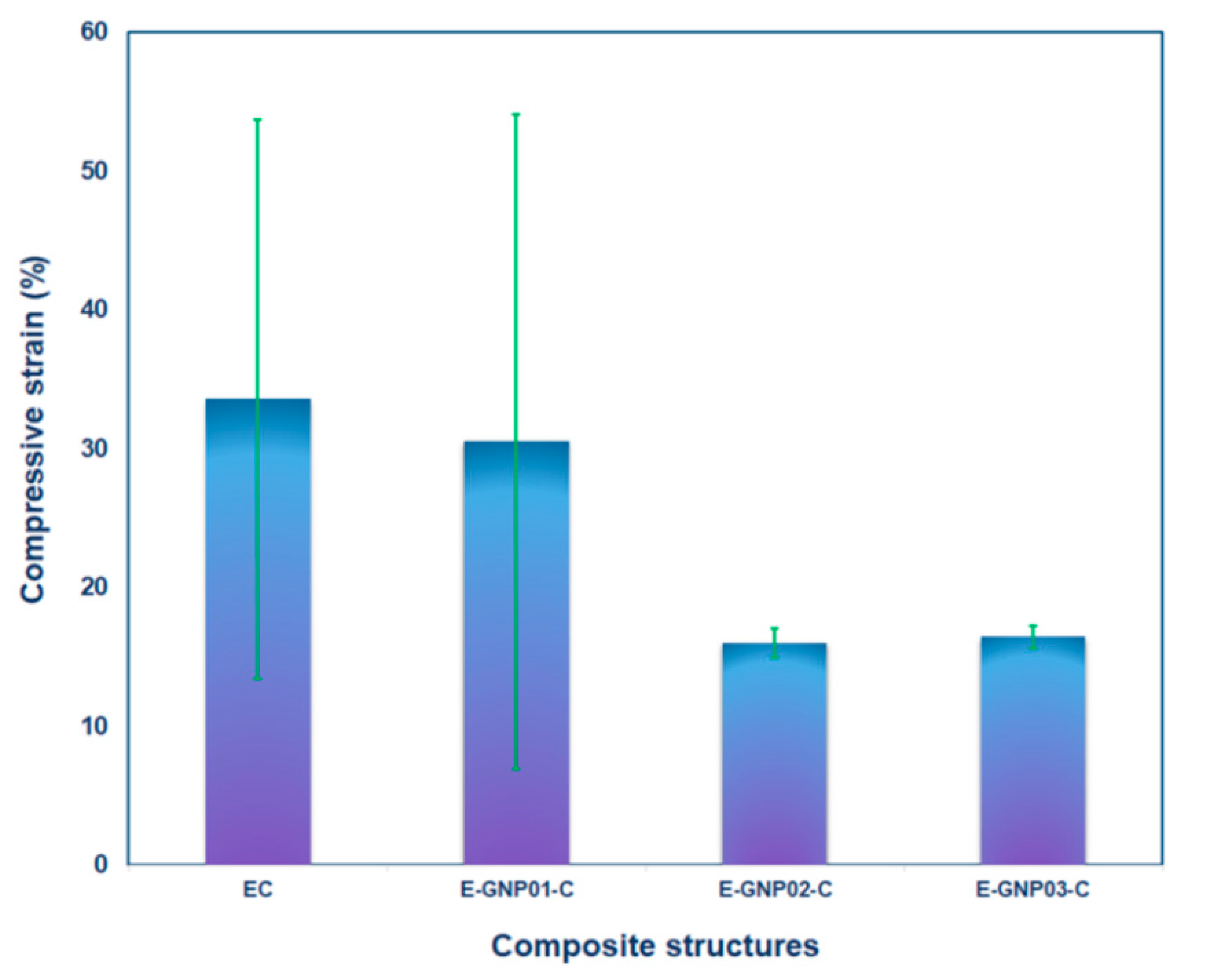
Compressive Strain
3.3. Fracture Morphology
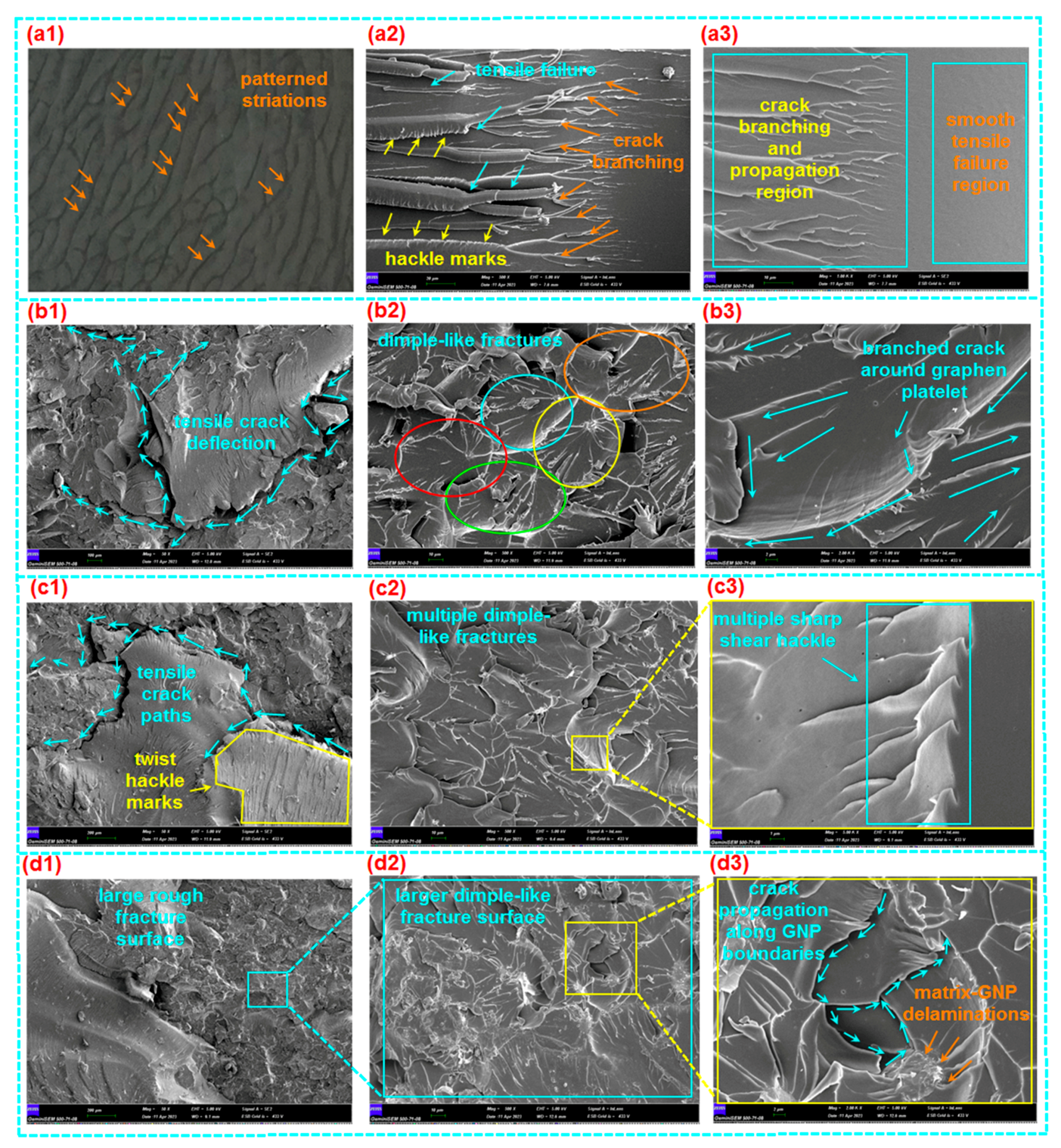
3.3.1. Tensile Fracture
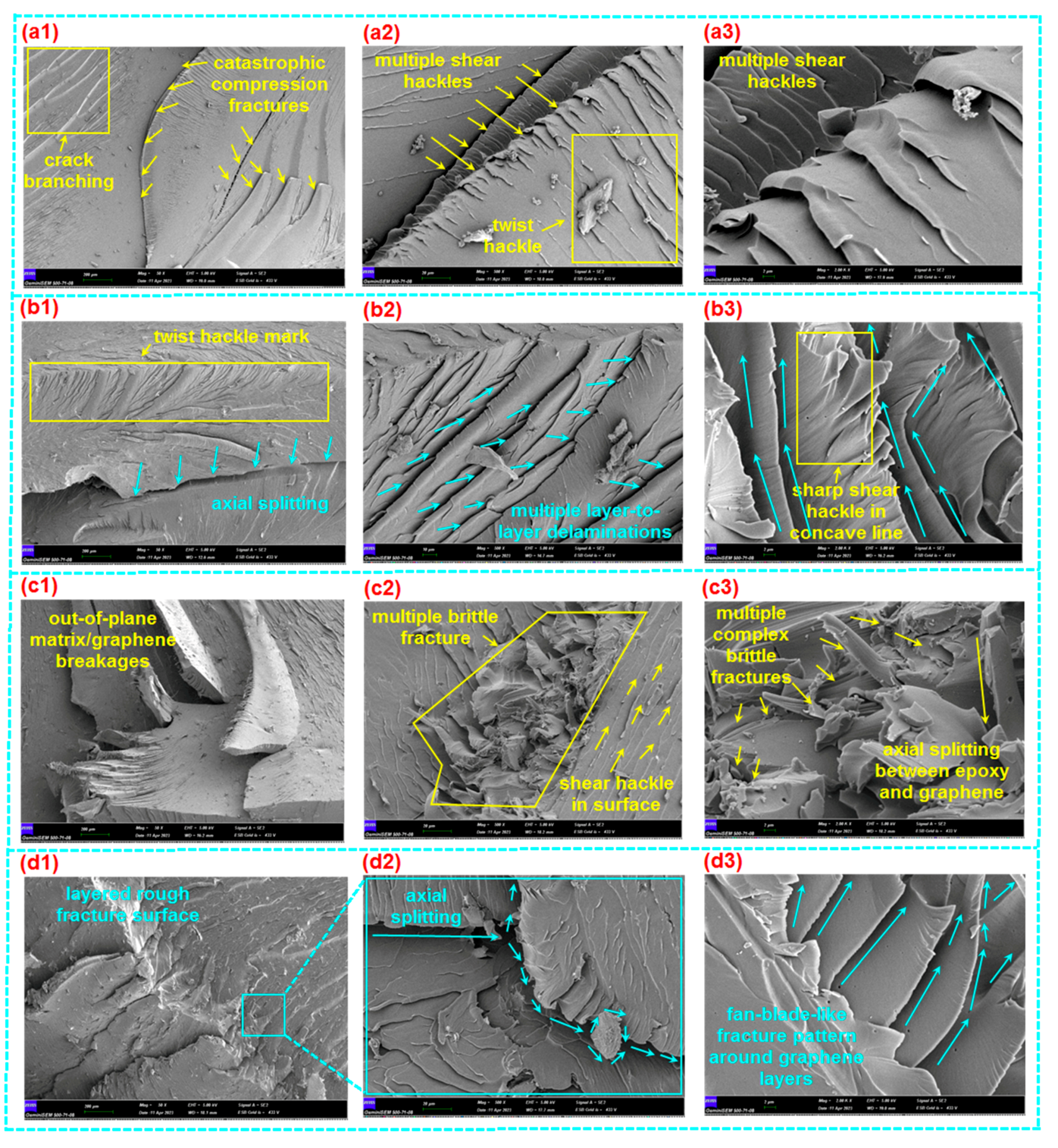
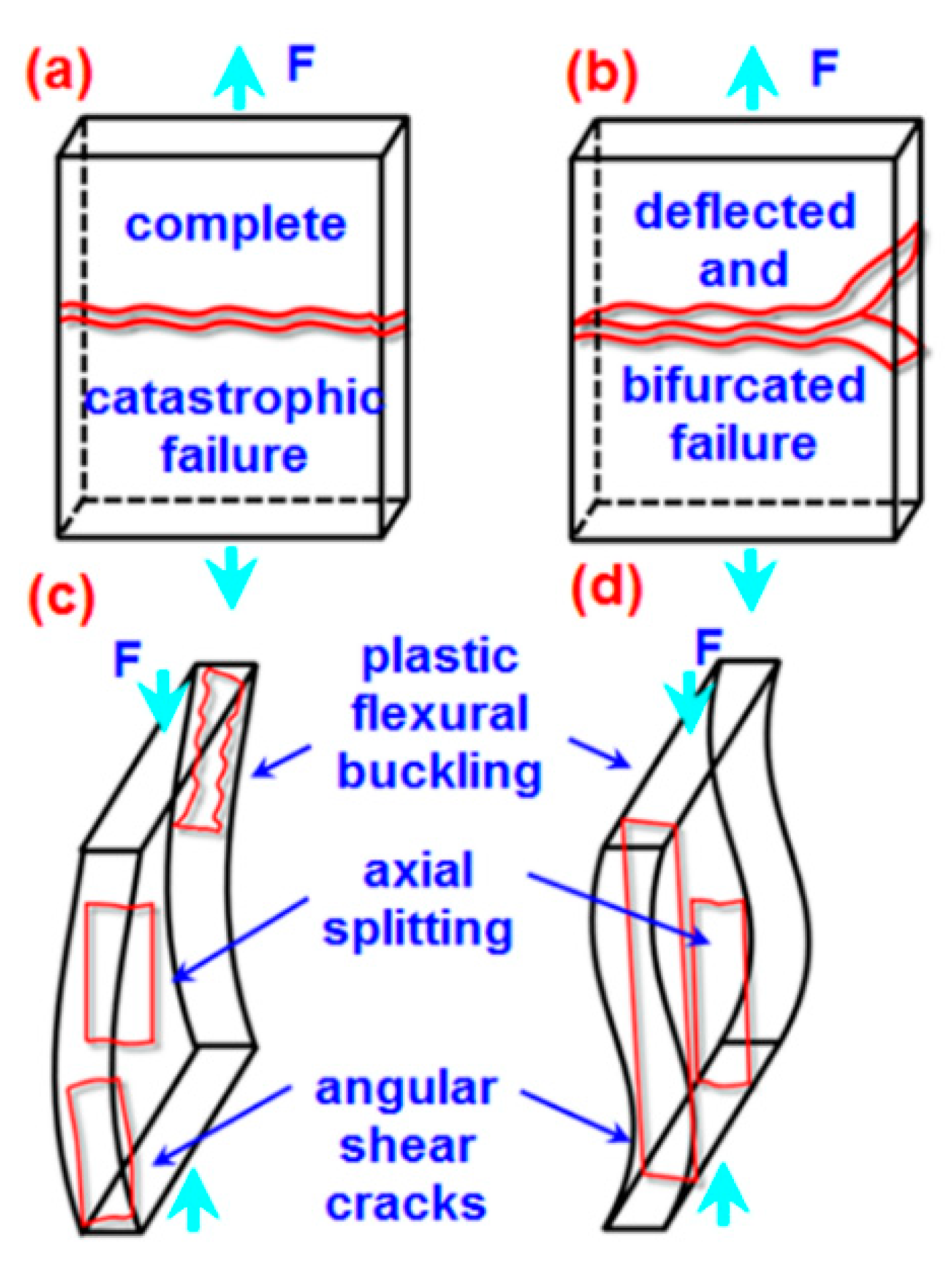
3.3.2. Compressive Fracture
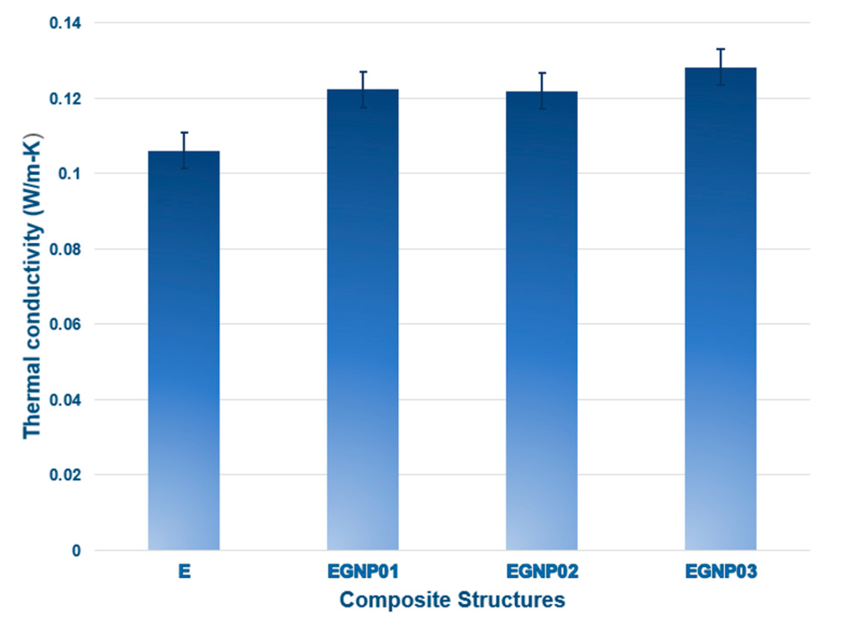
3.4. Thermal Conductivity
4. Conclusions
Author Contributions
Funding
Data Availability Statement
Acknowledgments
Conflicts of Interest
References
- de Oliveira, A.D.; Beatrice, C.A.G. Polymer nanocomposites with different types of nanofiller. In Nanocomposites—Recent Evolutions; Intech Open: London, UK, 2019. [Google Scholar] [CrossRef]
- Rajak, D.K.; Pagar, D.D.; Menezes, P.L.; Emanoil, L. Fiber-reinforced polymer composites: Manufacturing, properties, and applications. Polymers 2019, 11, 1667. [Google Scholar] [CrossRef] [PubMed]
- Li, B.; Zhong, W.H. Review on polymer/graphite nanoplatelet nanocomposites. J. Mater. Sci. 2011, 46, 5595–5614. [Google Scholar] [CrossRef]
- Saravanan, N.; Rajasekar, R.; Mahalakshmi, S.; Sathishkumar, T.P.; Sasikumar, K.S.K.; Sahoo, S. Graphene and modified gra-phene-based polymer nanocomposites—A review. J. Reinf. Plast. Compos. 2014, 33, 1158–1170. [Google Scholar] [CrossRef]
- Yazyev, O.V.; Chen, P. Polycrystalline graphene and other two-dimensional materials. Nat. Nanotechnol. 2014, 9, 755–767. [Google Scholar] [CrossRef]
- Bao, C.; Guo, Y.; Song, L.; Kan, Y.; Qian, X.; Hu, Y. In situ preparation of functionalized graphene oxide/epoxy nanocomposites with effective reinforcements. J. Mater. Chem. 2011, 21, 13290–13298. [Google Scholar] [CrossRef]
- Raval, B.; Sahare, P.D.; Mahapatra, S.K.; Banerjee, I. Enhanced capacitive behaviour of graphene nanoplatelets embedded epoxy nanocomposite. J. Mater. Sci. Mater. Electron. 2021, 32, 4034–4044. [Google Scholar] [CrossRef]
- Bhattacharya, M. Polymer nanocomposites—A comparison between carbon nanotubes, graphene, and clay as nanofillers. Materials 2016, 9, 262. [Google Scholar] [CrossRef] [PubMed]
- Young, R.J.; Kinloch, I.A.; Gong, L.; Novoselov, K.S. The mechanics of graphene nanocomposites: A review. Compos. Sci. Technol. 2012, 72, 1459–1476. [Google Scholar] [CrossRef]
- Awwad, K.Y.E.; Yousif, B.F.; Fallahnezhad, K.; Saleh, K.; Zeng, X. Influence of graphene nanoplatelets on mechanical proper-ties and adhesive wear performance of epoxy-based composites. Friction 2021, 9, 856–875. [Google Scholar] [CrossRef]
- Balandin, A.A.; Ghosh, S.; Bao, W.; Calizo, I.; Teweldebrhan, D.; Miao, F.; Lau, C.N. Superior thermal conductivity of sin-gle-layer graphene. Nano Lett. 2008, 8, 902–907. [Google Scholar] [CrossRef]
- Zaman, I.; Phan, T.T.; Kuan, H.C.; Meng, Q.; Bao, L.T.; Luong, L.; Youssf, O.; Ma, J. Epoxy/graphene platelets nano-composites with two levels of interface strength. Polymer 2011, 52, 1603–16011. [Google Scholar] [CrossRef]
- Zaman, I.; Kuan, H.C.; Dai, J.; Kawashima, N.; Michelmore, A.; Sovi, A.; Dong, S.; Luong, L.; Ma, J. From carbon nanotubes and silicate layers to graphene platelets for polymer nanocomposites. Nanoscale 2012, 4, 4578–4586. [Google Scholar] [CrossRef]
- Yue, L.; Pircheraghi, G.; Monemian, S.A.; Manas-Zloczower, I. Epoxy composites with carbon nanotubes and graphene nano-platelets—Dispersion and synergy effects. Carbon 2014, 78, 268–278. [Google Scholar] [CrossRef]
- Yang, Y.; Xu, Z.H.; Pan, Z.; Li, X. Hydrogen passivation induced dispersion of multi-walled carbon nanotubes. Adv. Mater. 2012, 24, 881–885. [Google Scholar] [CrossRef]
- Wei, J.; Vo, T.; Inam, F. Epoxy/graphene nanocomposites—Processing and properties: A review. RSC Adv. 2015, 5, 73510–73524. [Google Scholar] [CrossRef]
- Yang, K.; Zhang, F.; Chen, Y.; Zhang, H.; Xiong, B.; Chen, H. Recent progress on carbon-based composites in multidimen-sional applications. Compos. Part A Appl. Sci. Manuf. 2022, 157, 106906. [Google Scholar] [CrossRef]
- Stankovich, S.; Dikin, D.A.; Dommett, G.H.B.; Kohlhaas, K.M.; Zimney, E.J.; Stach, E.A.; Piner, R.D.; Nguyen, S.T.; Ruoff, R.S. Graphene-based composite materials. Nature 2006, 442, 282–286. [Google Scholar] [CrossRef]
- Debelak, B.; Lafdi, K. Use of exfoliated graphite filler to enhance polymer physical properties. Carbon 2007, 45, 1727–1734. [Google Scholar] [CrossRef]
- Ganguli, S.; Roy, A.K.; Anderson, D.P. Improved thermal conductivity for chemically functionalized exfoliated graphite/epoxy composites. Carbon 2008, 46, 806–817. [Google Scholar] [CrossRef]
- Kim, H.; Hahn, H.T.; Viculis, L.M.; Gilje, S.; Kaner, R.B. Electrical conductivity of graphite/polystyrene composites made from potassium intercalated graphite. Carbon 2007, 45, 1578–1582. [Google Scholar] [CrossRef]
- Mohan, V.B.; Lau, K.T.; Hui, D.; Bhattacharyya, D. Graphene-based materials and their composites: A review on production, applications and product limitations. Compos. Part B Eng. 2018, 142, 200–220. [Google Scholar] [CrossRef]
- Wu, Z.S.; Ren, W.; Gao, L.; Liu, B.; Jiang, C.; Cheng, H.M. Synthesis of high-quality graphene with a pre-determined number of layers. Carbon 2009, 47, 493–499. [Google Scholar] [CrossRef]
- Kalaitzidou, K.; Fukushima, H.; Drzal, L.T. Multifunctional polypropylene composites produced by incorporation of exfoliated graphite nanoplatelets. Carbon 2007, 45, 1446–1452. [Google Scholar] [CrossRef]
- Xiao, W.; Li, B.; Yan, J.; Wang, L.; Huang, X.; Gao, J. Three dimensional graphene composites: Preparation, morphology and their multi-functional applications. Compos. Part A Appl. Sci. Manuf. 2023, 165, 107335. [Google Scholar] [CrossRef]
- Yee, K.; Ghayesh, M.H. A review on the mechanics of graphene nanoplatelets reinforced structures. Int. J. Eng. Sci. 2023, 186, 103831. [Google Scholar] [CrossRef]
- Zhang, X.; Alloul, O.; He, Q.; Zhu, J.; Verde, M.J.; Li, Y.; Wei, S.; Guo, Z. Strengthened magnetic epoxy nanocomposites with protruding nanoparticles on the graphene nanosheets. Polymer 2013, 54, 3594–3604. [Google Scholar] [CrossRef]
- Wang, F.; Drzal, L.T.; Qin, Y.; Huang, Z. Mechanical properties and thermal conductivity of graphene nanoplatelet/epoxy composites. J. Mater. Sci. 2014, 50, 1082–1093. [Google Scholar] [CrossRef]
- Anwer, M.A.S.; Wang, J.; Naguib, H.E. 1D/2D CNF/GNP hybrid nanofillers: Evaluation of the effect of surfactant on the mor-phological, mechanical, fracture, and thermal characteristics of their nanocomposites with epoxy resin. Ind. Eng. Chem. Res. 2019, 58, 8131–8139. [Google Scholar] [CrossRef]
- Mohan, P. A critical review: The modification, properties, and applications of epoxy resins. Polym. Plast. Technol. Eng. 2013, 52, 107–125. [Google Scholar] [CrossRef]
- Hashim, U.R.; Jumahat, A. Improved tensile and fracture toughness properties of graphene nanoplatelets filled epoxy poly-mer via solvent compounding shear milling method. Mater. Res. Express 2018, 6, 025303. [Google Scholar] [CrossRef]
- Zotti, A.; Zuppolini, S.; Zarrelli, M.; Borriello, A.J.A.A. Fracture toughening mechanisms in epoxy adhesives. In Adhesives-Applications and Properties; Rudawska, A., Ed.; Intech Open: London, UK, 2016; pp. 237–269. [Google Scholar] [CrossRef]
- Berhanuddin, N.I.C.; Zaman, I.; Rozlan, S.A.M.; Karim, M.A.A.; Manshoor, B.; Khalid, A.; Chan, S.W.; Meng, Q. Enhance-ment of mechanical properties of epoxy/graphene nanocomposite. J. Physics Conf. Ser. 2017, 914, 012036. [Google Scholar] [CrossRef]
- Shen, M.Y.; Chang, T.Y.; Hsieh, T.H.; Li, Y.L.; Chiang, C.L.; Yang, H.; Yip, M.C. Mechanical properties and tensile fatigue of graphene nanoplatelets reinforced polymer nanocomposites. J. Nanomater. 2013, 565401. [Google Scholar] [CrossRef]
- Chiou, Y.C.; Chou, H.Y.; Shen, M.Y. Effects of adding graphene nanoplatelets and nanocarbon aerogels to epoxy resins and their carbon fiber composites. Mater. Des. 2019, 178, 107869. [Google Scholar] [CrossRef]
- Khalid, N.A.; Razak, J.A.; Ismail, M.M.; Flaifel, M.H.; Puspitasari, P. Polyaniline/graphene nanoplatelets-silver (pani/gnps-ag) nanocomposites treated via non-covalent surface functionalization method. Malays. J. Microsc. 2023, 19, 208–219. [Google Scholar]
- Flaifel, M.H.; Zakaria, M.Z.; Ahmad, S.H. The influence of adopted chemical modification route on the thermal and mechanical properties of alumina nanoparticles-impregnated thermoplastic natural rubber nanocomposite. Arab. J. Sci. Eng. 2020, 45, 1181–1190. [Google Scholar] [CrossRef]
- Shahdan, D.; Flaifel, M.H.; Ahmad, S.H.; Chen, R.S.; Razak, J.A. Enhanced magnetic nanoparticles dispersion effect on the behaviour of ultrasonication-assisted compounding processing of PLA/LNR/NiZn nanocomposites. J. Mater. Res. Technol. 2021, 15, 5988–6000. [Google Scholar] [CrossRef]
- Shahdan, D.; Flaife, M.H.; Chen, R.S.; Ahmad, S.; Hassan, A. Role of sonication time on thermal behaviour and dynamic mechanical analysis of NiZn ferrite incorporated PLA/LNR nanocomposite. Bull. Mater. Sci. 2019, 42, 78. [Google Scholar] [CrossRef]
- Tarawneh, M.A.; Ahmad, S.H.; Zarina, K.A.K.; Hassan, I.N.; Jiun, Y.L.; Flaifel, M.H.; Bahri, A.R.S. Properties enhancement of TPNR-MWNTs-OMMT hybrid nanocomposites by using ultrasonic treatment. Sains Malays. 2013, 42, 503–507. [Google Scholar]
- Singh, N.P.; Gupta, V.K.; Singh, A.P. Graphene and carbon nanotube reinforced epoxy nanocomposites: A review. Polymer 2019, 180, 121724. [Google Scholar] [CrossRef]
- Zotti, A.; Zuppolini, S.; Borriello, A.; Zarrelli, M. Polymer nanocomposites based on graphite nanoplatelets and amphiphilic graphene platelets. Compos. Part B Eng. 2022, 246, 110223. [Google Scholar] [CrossRef]
- Tang, L.C.; Wan, Y.J.; Yan, D.; Pei, Y.B.; Zhao, L.; Li, Y.B.; Wu, L.B.; Jiang, J.X.; Lai, G.Q. The effect of graphene dispersion on the mechanical properties of graphene/epoxy composites. Carbon 2013, 60, 16–27. [Google Scholar] [CrossRef]
- Kang, Y.A.; Kim, M.H.; Noh, H.J.; Baek, J.B.; Jeon, I.Y. Reinforcement of polystyrene using edge-styrene graphitic nanoplate-lets. J. Mater. Res. Technol. 2021, 10, 662–670. [Google Scholar] [CrossRef]
- Chakraborty, M.; Hashmi, M.S.J. Wonder material graphene: Properties, synthesis and practical applications. Adv. Mater. Proc. Technol. 2018, 4, 573–602. [Google Scholar] [CrossRef]
- Chatterjee, S.; Nafezarefi, F.; Tai, N.H.; Schlagenhauf, L.; Nüesch, F.A.; Chu, B.T.T. Size and synergy effects of nanofiller hy-brids including graphene nanoplatelets and carbon nanotubes in mechanical properties of epoxy composites. Carbon 2012, 50, 5380–5386. [Google Scholar] [CrossRef]
- Yasmin, A.; Daniel, I.M. Mechanical and thermal properties of graphite platelet/epoxy composites. Polymer 2004, 45, 8211–8219. [Google Scholar] [CrossRef]
- Prolongo, S.G.; Moriche, R.; Jiménez-Suárez, A.; Sánchez, M.; Ureña, A. Epoxy adhesives modified with graphene for thermal interface materials. J. Adhes. 2014, 90, 835–847. [Google Scholar] [CrossRef]
- Shen, X.J.; Liu, Y.; Xiao, H.M.; Feng, Q.P.; Yu, Z.Z.; Fu, S.Y. The reinforcing effect of graphene nanosheets on the cryogenic mechanical properties of epoxy resins. Compos. Sci. Technol. 2012, 72, 1581–1587. [Google Scholar] [CrossRef]
- Yao, H.; Hawkins, S.A.; Sue, H.J. Preparation of epoxy nanocomposites containing well-dispersed graphene nanosheets. Compos. Sci. Technol. 2017, 146, 161–168. [Google Scholar] [CrossRef]
- Rafiee, M.A.; Rafiee, J.; Srivastava, I.; Wang, Z.; Song, H.; Yu, Z.Z.; Koratkar, N. Fracture and fatigue in graphene nanocomposites. Small 2010, 6, 179–183. [Google Scholar] [CrossRef]
- Wan, Y.J.; Gong, L.X.; Tang, L.C.; Wu, L.B.; Jiang, J.X. Mechanical properties of epoxy composites filled with silane-functionalized graphene oxide. Compos. Part A Appl. Sci. Manuf. 2014, 64, 79–89. [Google Scholar] [CrossRef]
- Mostovoy, A.; Amirbek Bekeshev, A.; Brudnik, S.; Yakovlev, A.; Shcherbakov, A.; Zhanturina, N.; Zhumabekova, A.; Yakovleva, E.; Tseluikin, V.; Lopukhova, M. Studying the structure and properties of epoxy composites modified by original and functionalized with hexamethylenediamine by electrochemically synthesized graphene oxide. Nanomaterials 2024, 14, 602. [Google Scholar] [CrossRef]
- Li, Z.; Wang, R.; Young, R.J.; Deng, L.; Yang, F.; Hao, L.; Jiao, W.; Liu, W. Control of the functionality of graphene oxide for its application in epoxy nanocomposites. Polymer 2013, 54, 6437–6446. [Google Scholar] [CrossRef]
- Chandrasekaran, S.; Sato, N.; Tölle, F.; Mülhaupt, R.; Fiedler, B.; Schulte, K. Fracture toughness and failure mechanism of graphene based epoxy composites. Compos. Sci. Technol. 2014, 97, 90–99. [Google Scholar] [CrossRef]
- Thostenson, E.; Li, C.; Chou, T.W. Nanocomposites in context. Compos. Sci. Technol. 2005, 65, 491–516. [Google Scholar] [CrossRef]
- Wang, J.; Wang, X.; Xu, C.; Zhang, M.; Shang, X. Preparation of graphene/poly(vinyl alcohol) nanocomposites with enhanced mechanical properties and water resistance. Poly. Int. 2011, 60, 816–822. [Google Scholar] [CrossRef]
- Ji, X.Y.; Cao, Y.P.; Feng, X.Q. Micromechanics prediction of the effective elastic moduli of graphene sheet-reinforced polymer nanocomposites. Model. Simul. Mat. Sci. Eng. 2010, 18, 045005. [Google Scholar] [CrossRef]
- Bandyopadhyay, A.; Valavala, P.K.; Clancy, T.C.; Wise, K.E.; Odegard, G.M. Molecular modeling of cross-linked epoxy polymers: The effect of crosslink density on thermo mechanical properties. Polymer 2011, 52, 2445–2452. [Google Scholar] [CrossRef]
- Wu, C.F.; Xu, W.J. Atomistic molecular modelling of crosslinked epoxy resin. Polymer 2006, 47, 6004–6009. [Google Scholar] [CrossRef]
- Rahman, R.; Haque, A. Molecular modeling of crosslinked graphene–epoxy nanocomposites for characterization of elastic constants and interfacial properties. Compos. Part B Eng. 2013, 54, 353–364. [Google Scholar] [CrossRef]
- Nanoth, R.; Jayanarayanan, K.; Kumar, P.S.; Balachandran, M.; Pegoretti, A. Static and dynamic mechanical properties of hy-brid polymer composites: A comprehensive review of experimental, micromechanical and simulation approaches. Compos. Part A Appl. Sci. Manuf. 2023, 174, 107741. [Google Scholar] [CrossRef]
- ASTM D3039/D3039M-14; Standard Test Method for Tensile Properties of Polymer Matrix Composite Materials. ASTM International: West Conshohocken, PA, USA, 2014.
- ASTM D695-15; Standard Test Method for Compressive Properties of Rigid Plastics. ASTM International: West Conshohocken, PA, USA, 2015.
- ASTM C 518-02e1; Standard Test Method for Steady-State Thermal Transmission Properties by Means of the Heat Flow Meter Apparatus. ASTM International: West Conshohocken, PA, USA, 2002.
- Dresselhaus, M.S.; Dresselhaus, G.; Saito, R.; Jorio, A. Raman spectroscopy of carbon nanotubes. Phys. Rep. 2005, 409, 47–99. [Google Scholar] [CrossRef]
- Shea, M.J.; Wall, M.H. Representative raman measurements of carbon nanotubes. Spectrosc. Eur. 2012, 24, 1–3. [Google Scholar]
- Nečas, D.; Klapetek, P.G. An open-source software for SPM data analysis. Central Eur. J. Phys. 2012, 10, 181–188. [Google Scholar] [CrossRef]
- ASTM D792; Standard Test Methods for Density and Specific Gravity (Relative Density) of Plastics by Displacement. ASTM International: West Conshohocken, PA, USA, 2018; pp. 1–6. [CrossRef]
- Socrates, G. Infrared and Raman Characteristic Group Frequencies: Tables and Charts; John Wiley & Sons: New York, NY, USA, 2004; pp. 1–368. [Google Scholar]
- Österle, W.; Giovannozzi, A.; Gradt, T.; Häusler, I.; Rossi, A.; Wetzel, B.; Zhang, G.; Dmitriev, A.I. Exploring the potential of Raman spectroscopy for the identification of silicone oil residue and wear scar characterization for the assessment of tribofilm functionality. Tribology Int. 2015, 90, 481–490. [Google Scholar] [CrossRef]
- Kilic, U.; Sherif, M.M.; Ozbulut, O.E. Tensile properties of graphene nanoplatelets/epoxy composites fabricated by various dispersion techniques. Polym. Test. 2019, 76, 181–191. [Google Scholar] [CrossRef]
- Liang, J.Z.; Du, Q.; Tsui, G.C.P.; Tang, C.Y. Tensile properties of graphene nano-platelets reinforced polypropylene composites. Compos. Part B Eng. 2016, 95, 166–171. [Google Scholar] [CrossRef]
- Kesavulu, A.; Mohanty, A. Compressive performance and thermal stability of alumina—Graphene nanoplatelets reinforced epoxy nanocomposites. Mater. Res. Express. 2019, 6, 125329. [Google Scholar] [CrossRef]
- Khan, N.I.; Halder, S.; Talukdar, N.; Das, S.; Goyat, M.S. Surface oxidized/silanized graphite nanoplatelets for reinforcing an epoxy matrix. Mater. Chem. Phys. 2021, 258, 123851. [Google Scholar] [CrossRef]
- Ayatollahi, M.R.; Shadlou, S.; Shokrieh, M.M.; Chitsazzadeh, M. Effect of multi-walled carbon nanotube aspect ratio on mechanical and electrical properties of epoxy-based nanocomposites. Poly. Test. 2011, 30, 548–556. [Google Scholar] [CrossRef]
- Das, S.; Halder, S.; Sinha, A.; Imam, M.A.; Khan, N.I. Assessing nanoscratch behavior of epoxy nanocomposite toughened with silanized fullerene. ACS Appl. Nano Mater. 2018, 1, 3653–3662. [Google Scholar] [CrossRef]
- Rizal, S.; Homma, H. Dimple fracture under short pulse loading. Int. J. Impact Eng. 2000, 24, 69–83. [Google Scholar] [CrossRef]
- Ono, T.; Allaire, R.A. Fracture Analysis, a Basic Tool to Solve Breakages Issues; Technical Information paper (TIP 201); Corning Inc.: Corning, NY, USA, 2000. [Google Scholar]
- Leopold, C.; Just, G.; Koch, I.; Schetle, A.; Kosmann, J.B.; Gude, M.; Fiedler, B. Damage mechanisms of tailored few-layer graphene modified CFRP crossply laminates. Compos. Part A Appl. Sci. Manuf. 2019, 117, 332–344. [Google Scholar] [CrossRef]
- Rafiee, M.A.; Rafiee, J.; Wang, Z.; Song, H.; Yu, Z.Z.; Koratkar, N. Enhanced mechanical properties of nanocomposites at low graphene content. ACS Nano 2019, 3, 3884–3890. [Google Scholar] [CrossRef] [PubMed]
- Bilisik, K. Bending behavior of multilayered and multidirectional stitched aramid woven fabric structures. Text. Res. J. 2011, 81, 1748–1761. [Google Scholar] [CrossRef]
- Quaresimin, M.; Schulte, K.; Zappalorto, M.; Chandrasekaran, S. Toughening mechanisms in polymer nanocomposites: From experiments to modeling. Compos. Sci. Technol. 2015, 123, 187–204. [Google Scholar] [CrossRef]
- Kendall, K.; Cottrell, A.H. Complexities of compression failure. Proc. R Soc. A 1978, 361, 245–263. [Google Scholar] [CrossRef]
- Bilisik, K. Stick–slip behavior of para-aramid (Twaron®) fabric in yarn pull-out. Text. Res. J. 2013, 83, 13–33. [Google Scholar] [CrossRef]
- Teng, C.C.; Ma, C.C.M.; Lu, C.H.; Yang, S.Y.; Lee, S.H.; Hsiao, M.C.; Yen, M.Y.; Chiou, K.C.; Lee, T.M. Thermal conductivity and structure of non-covalent functionalized graphene/epoxy composites. Carbon 2019, 49, 5107–5116. [Google Scholar] [CrossRef]
- Wang, Y.; Yu, J.; Dai, W.; Song, Y.; Wang, D.; Zeng, L.; Jiang, N. Enhanced thermal and electrical properties of epoxy composites reinforced with graphene nanoplatelets. Poly. Compos. 2015, 36, 556–565. [Google Scholar] [CrossRef]


| Supplier | Type | Density (g/cm3) | Viscosity (m Pas) | Operating Temperature (°C) |
|---|---|---|---|---|
| Epoxy Resin Dost Kimya Co, TR Hardener Dost Kimya Co, TR | A modified version of bisphenol A/F (MGS L326) | 1.14–1.19 | 5000–7000 | −60/+150 |
| A modified version of cycloaliphatic amines (MGS H265) | 0.91–0.93 | 10–20 | −60/+150 |
| Sample Number | Composite Code | Sampling Type |
|---|---|---|
| 01 | E | Neat epoxy |
| 02 | E-GNP01 | Epoxy/GNPs (0.1 wt.%) |
| 03 | E-GNP02 | Epoxy/GNPs (0.2 wt.%) |
| 04 | E-GNP03 | Epoxy/GNPs (0.3 wt.%) |
| SI No. | Vibrations | Wavenumber (cm−1) |
|---|---|---|
| 01 | –OH stretching | 3381 |
| 02 | C–H stretching | 2800–3000 |
| 03 | Asymmetrical stretching of –CH of –CH2 group | 2928 |
| 04 | Symmetrical stretching of –CH of –CH3 group | 2868 |
| 05 | C––C stretching bands of aromatic rings | 1608 |
| 06 | N–O stretching | 1508 |
| 07 | Epoxy ring mode | 1294, 955, 875 |
| 08 | C–O stretching of the aromatic ring | 1180 |
| 09 | Symmetrical aromatic C–O stretching | 1035 |
| 10 | Aromatic ring bent out of plane | 826 |
| 11 | C–OH, C–H, N–H bend | 555 |
| Sample Number | Sample Description | Composite Panel Code | Average Density (g/cm3) | Standard Deviation | Coefficient of Variation |
|---|---|---|---|---|---|
| 01 | Neat Epoxy | E | 1.153 ± 0.002 | 0.0023 | 0.0020 |
| 02 | Epoxy/GNPs (0.1 wt.%) | E-GNP01 | 1.153 ± 0.000 | 0 | 0 |
| 03 | Epoxy/GNPs (0.2 wt.%) | E-GNP02 | 1.154 ± 0.001 | 0.0006 | 0.005 |
| 04 | Epoxy/GNPs (0.3 wt.%) | E-GNP03 | 1.154 ± 0.000 | 0 | 0 |
| Sample Code | Tensile Load (Max.) (N) | Displacement (mm) | Tensile Strength (MPa) | Tensile Modulus (GPa) | Tensile Strain Extensometer (%) |
|---|---|---|---|---|---|
| ET | 4980.50 | 4.11 | 31.61 ± 4.84 | 2.89 ± 0.13 | 6.85 ± 0.50 |
| E-GNP01-T | 7117.58 | 4.56 | 39.14 ± 19.21 | 2.81 ± 0.21 | 7.61 ± 3.36 |
| E-GNP02-T | 7626.10 | 4.13 | 41.04 ± 11.18 | 2.65 ± 0.66 | 6.88 ± 2.24 |
| E-GNP03-T | 10,247.78 | 6.06 | 54.25 ± 6.61 | 3.36 ± 0.55 | 10.10 ± 2.43 |
| Sample Code | Compressive Load (Max.) (N) | Compressive Displacement (mm) | Compressive Strength (MPa) | Compressive Strain (%) |
|---|---|---|---|---|
| EC | 19,702.30 | 0.787 | 117.97 ± 15.00 | 33.52 ± 20.12 |
| E-GNP01-C | 20,348.20 | 0.787 | 116.10 ± 11.49 | 30.25 ± 23.59 |
| E-GNP02-C | 18,986.27 | 0.818 | 109.78 ± 4.07 | 15.97 ± 1.03 |
| E-GNP03-C | 19,438.30 | 0.899 | 109.44 ± 2.06 | 16.40 ± 0.8 |
Disclaimer/Publisher’s Note: The statements, opinions and data contained in all publications are solely those of the individual author(s) and contributor(s) and not of MDPI and/or the editor(s). MDPI and/or the editor(s) disclaim responsibility for any injury to people or property resulting from any ideas, methods, instructions or products referred to in the content. |
© 2024 by the authors. Licensee MDPI, Basel, Switzerland. This article is an open access article distributed under the terms and conditions of the Creative Commons Attribution (CC BY) license (https://creativecommons.org/licenses/by/4.0/).
Share and Cite
Akter, M.; Ozdemir, H.; Bilisik, K. Epoxy/Graphene Nanoplatelet (GNP) Nanocomposites: An Experimental Study on Tensile, Compressive, and Thermal Properties. Polymers 2024, 16, 1483. https://doi.org/10.3390/polym16111483
Akter M, Ozdemir H, Bilisik K. Epoxy/Graphene Nanoplatelet (GNP) Nanocomposites: An Experimental Study on Tensile, Compressive, and Thermal Properties. Polymers. 2024; 16(11):1483. https://doi.org/10.3390/polym16111483
Chicago/Turabian StyleAkter, Mahmuda, Huseyin Ozdemir, and Kadir Bilisik. 2024. "Epoxy/Graphene Nanoplatelet (GNP) Nanocomposites: An Experimental Study on Tensile, Compressive, and Thermal Properties" Polymers 16, no. 11: 1483. https://doi.org/10.3390/polym16111483
APA StyleAkter, M., Ozdemir, H., & Bilisik, K. (2024). Epoxy/Graphene Nanoplatelet (GNP) Nanocomposites: An Experimental Study on Tensile, Compressive, and Thermal Properties. Polymers, 16(11), 1483. https://doi.org/10.3390/polym16111483