
Structural Design and Performance of Cut-Resistant Fabrics with Concave–Convex Arrays
Abstract
:1. Introduction
2. Materials and Methods
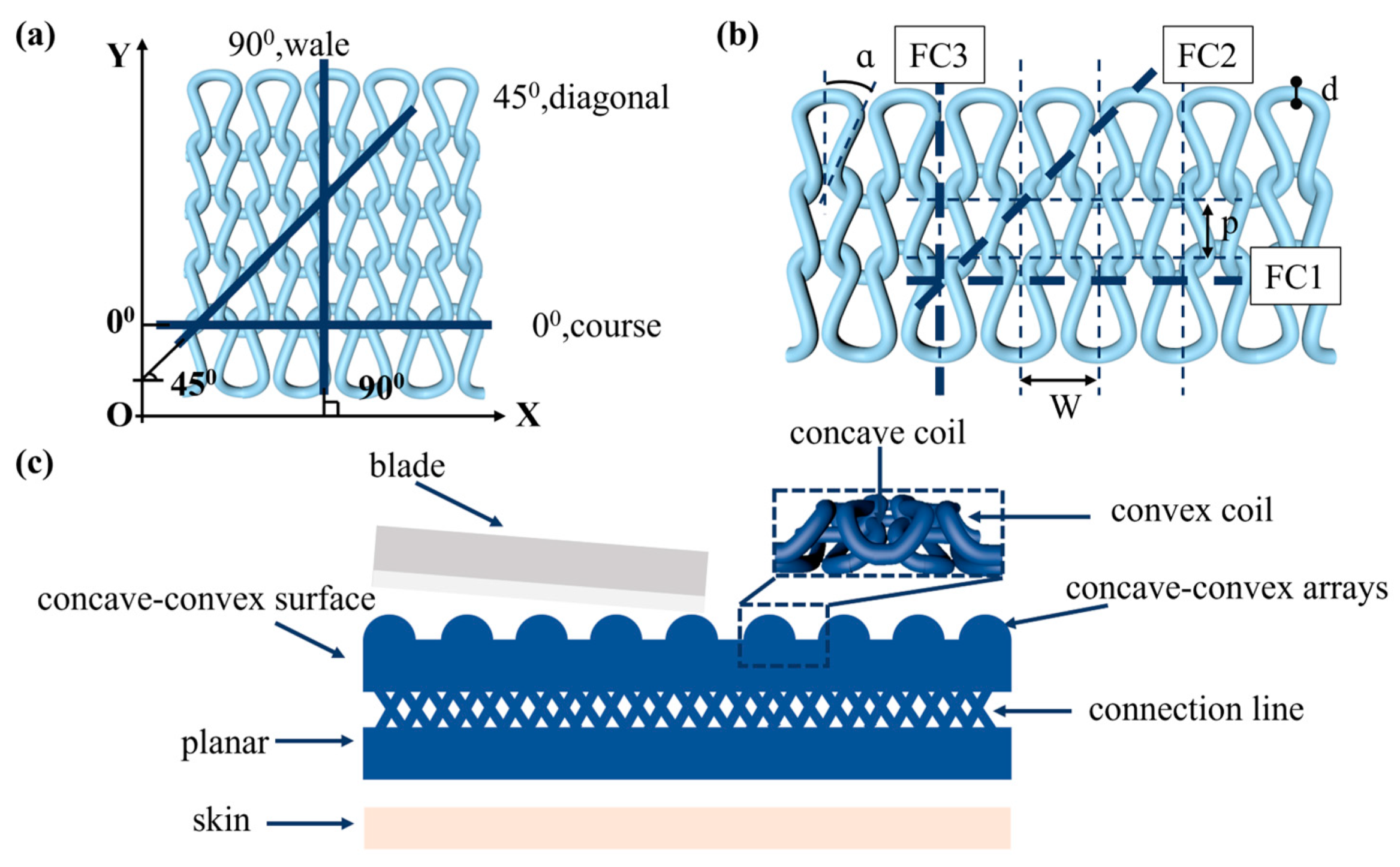
2.1. Design Principles
2.2. Fabric Structure Design
2.3. Fabric Preparation and Test Method
3. Results and Discussion
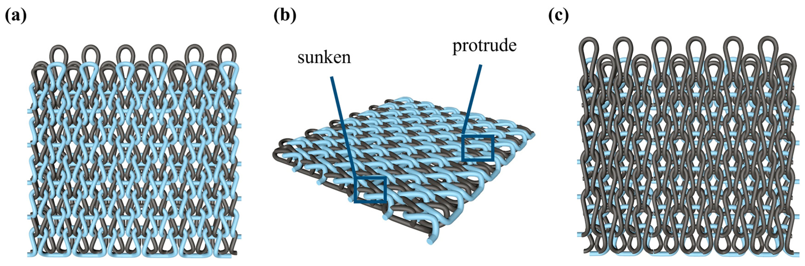
3.1. Fabric Characterization
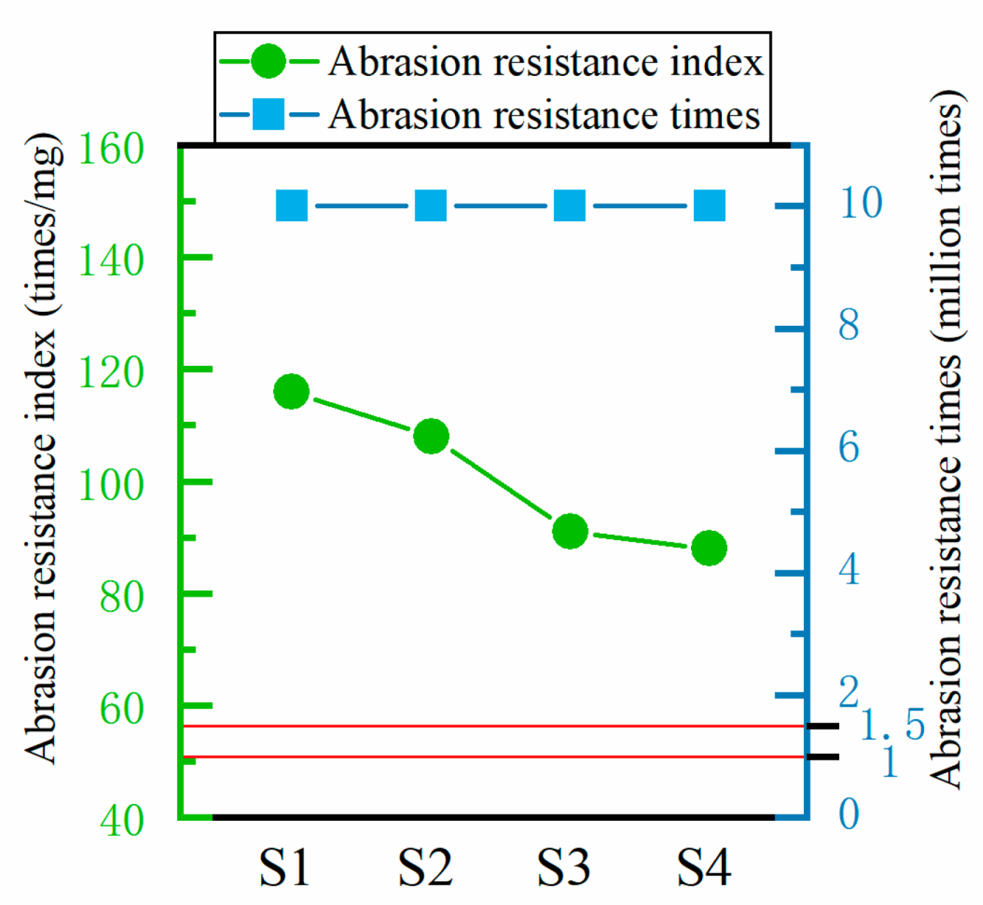
3.2. Performance of Abrasion Resistance
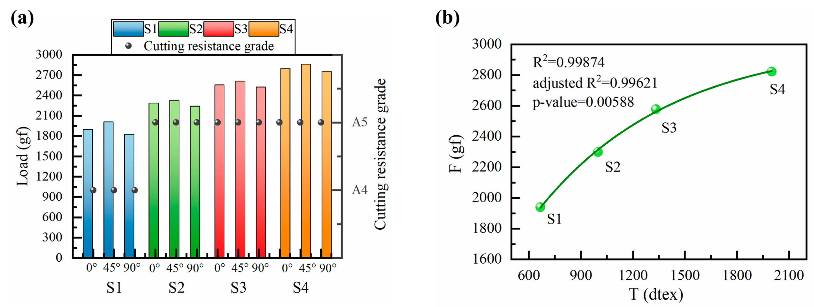
3.3. Performance of Cut Resistance
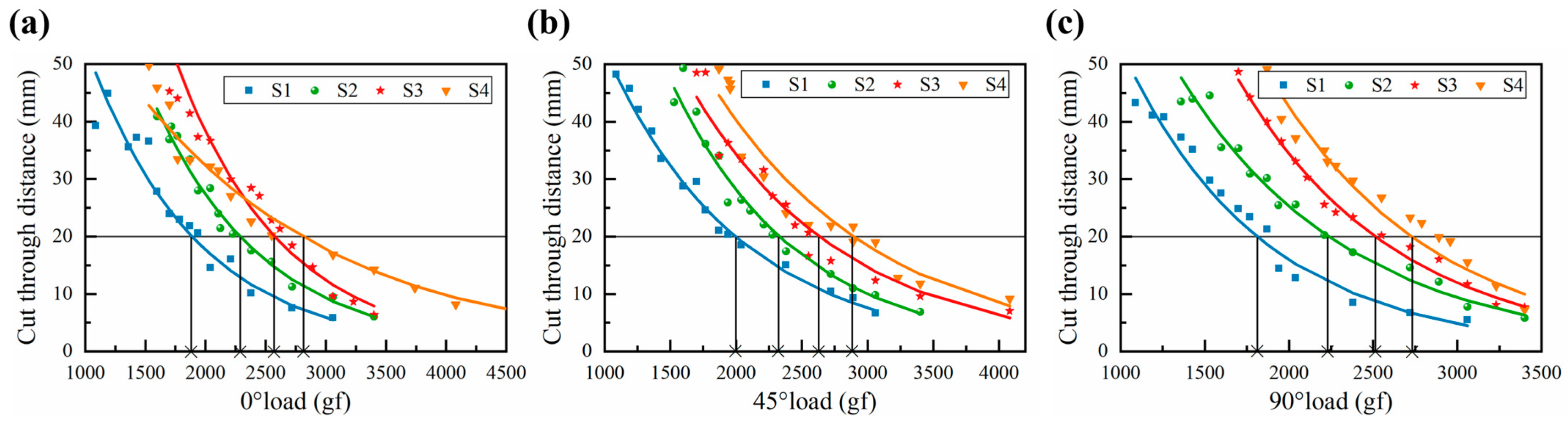
3.3.1. 0° Cut Resistance
3.3.2. 45° Cut Resistance
3.3.3. 90° Cut Resistance
3.3.4. Comprehensive Evaluation of Cut Resistance
3.4. Theoretical Analysis of Cut Resistance
4. Conclusions
Author Contributions
Funding
Institutional Review Board Statement
Data Availability Statement
Acknowledgments
Conflicts of Interest
References
- Zhao, Y.M.; Chen, Y.; Song, X.T.; Li, Y.; Zhang, L.M.; Meng, Y.Q.; Zhang, X.L.; Qiu, X.Y.; Huang, J. Starfish-Inspired Cut-Resistant Hydrogel with Self-Growing Armor: Where Softness Meets Toughness. Adv. Funct. Mater. 2023, 33, 2304439. [Google Scholar] [CrossRef]
- Nayak, R.; Crouch, I.; Kanesalingam, S.; Ding, J.; Tan, P.; Lee, B.; Miao, M.H.; Ganga, D.; Wang, L.J. Body armor for stab and spike protection, Part 1: Scientific literature review. Text. Res. J. 2018, 88, 812–832. [Google Scholar] [CrossRef]
- Panneke, N.; Ehrmann, A. Stab-Resistant Polymers—Recent Developments in Materials and Structures. Polymers 2023, 15, 983. [Google Scholar] [CrossRef] [PubMed]
- Mawkhlieng, U.; Majumdar, A.; Laha, A. A review of fibrous materials for soft body armour applications. RSC Adv. 2020, 10, 1066–1086. [Google Scholar] [CrossRef]
- Zylka, E.; Irzmanska, E.; Saramak, J.; Jurczyk-Kowalska, M. Functional 3D-Printed Polymeric Materials with Metallic Reinforcement for Use in Cut-Resistant Gloves. Materials 2024, 17, 90. [Google Scholar] [CrossRef]
- Zhon, L.; Xiao, Y.M.; Chen, H.X.; Huang, X.M.; Cao, H.J. Research status and prospect of anti-cutting fabric. Cotton Text. Technol. 2023, 51, 84–88. [Google Scholar]
- Govarthanam, K.K.; Anand, S.C.; Rajendran, S. Development of Advanced Personal Protective Equipment Fabrics for Protection Against Slashes and Pathogenic Bacteria Part 1: Development and Evaluation of Slash-resistant Garments. J. Ind. Text. 2010, 40, 139–155. [Google Scholar] [CrossRef]
- Li, L.; Liang, R.R.; Guo, J.; Quan, G.M. Design of Comfortable High Strength Anti-cutting Fabric. Cotton Text. Technol. 2022, 50, 26–31. [Google Scholar]
- Kropidlowska, P.; Jurczyk-Kowalska, M.; Irzmanska, E.; Plocinski, T.; Laskowski, R. Effects of Composite Coatings Functionalized with Material Additives Applied on Textile Materials for Cut Resistant Protective Gloves. Materials 2021, 14, 6876. [Google Scholar] [CrossRef]
- Yan, X.F.; Wu, L.L.; Jin, S.S.; Zhao, W.; Cao, H.J.; Ma, Y. Effect of curing conditions on the cutting resistance of fabrics coated with inorganic-powder-reinforced epoxy composite. RSC Adv. 2020, 10, 33576–33584. [Google Scholar] [CrossRef]
- Mao, L.Z.; Zhou, M.J.; Yao, L.; Yu, H.; Yan, X.F.; Shen, Y.; Chen, W.S.; Ma, P.B.; Ma, Y.; Zhang, S.L.; et al. Crocodile Skin-Inspired Protective Composite Textiles with Pattern-Controllable Soft-Rigid Unified Structures. Adv. Funct. Mater. 2023, 33, 2213419. [Google Scholar] [CrossRef]
- Tien, D.T.; Kim, J.S.; Huh, Y. Evaluation of anti-stabbing performance of fabric layers woven with various hybrid yarns under different fabric conditions. Fiber. Polym. 2011, 12, 808–815. [Google Scholar] [CrossRef]
- Tian, L.X.; Shi, J.J.; Chen, H.X.; Huang, X.M.; Cao, H.J. Cut-resistant performance of Kevlar and UHMWPE covered yarn fabrics with different structures. J. Text. Inst. 2022, 113, 1457–1463. [Google Scholar] [CrossRef]
- Lin, T.R.; Lin, T.A.; Lin, M.C.; Lin, Y.Y.; Lou, C.W.; Lin, J.H. Impact resistance of fiber reinforced sandwich-structured nonwoven composites: Reinforcing effect of different fiber length. Mater. Today Commun. 2020, 24, 101345. [Google Scholar] [CrossRef]
- Lin, T.R.; Lin, Y.Y.; Lin, T.A.; Jhang, J.C.; Lou, C.W.; Lin, J.H. Effects of Heat Treatments on Puncture Resistant Properties of Polyamine and Polyamide-based Nonwoven Fabrics. Fiber. Polym. 2020, 21, 2118–2124. [Google Scholar] [CrossRef]
- Venkataraman, D.; Shabani, E.; Park, J.H. Advancement of Nonwoven Fabrics in Personal Protective Equipment. Materials 2023, 16, 3964. [Google Scholar] [CrossRef] [PubMed]
- Cai, W.; Li, T.; Zhang, X. Polyacrylate and Carboxylic Multi-Walled Carbon Nanotube-Strengthened Aramid Fabrics as Flexible Puncture-Resistant Composites for Anti-Stabbing Applications. ACS Appl. Nano Mater. 2023, 6, 6334–6344. [Google Scholar] [CrossRef]
- Zhang, X.; Li, T.T.; Peng, H.K.; Lou, C.W.; Lin, J.H. Enhanced sandwich structure composite with shear thickening fluid and thermoplastic polyurethanes for High-performance stab resistance. Compos. Struct. 2022, 280, 114930. [Google Scholar] [CrossRef]
- Rao, S.V.S.; Midha, V.; Kumar, N. Studies on the stab resistance and ergonomic comfort behaviour of multilayer STF-treated tri-component woven fabric and HPPE laminate composite material. J. Text. Inst. 2024, 115, 573–580. [Google Scholar] [CrossRef]
- Liu, Q.; Chen, F.X.; Dong, T.T.; Yu, W.R.; Chen, C.Y.; Jiang, G.M.; Dong, Z.J.; Ma, P.B. Large-scale Fabrication of Snake-skin-inspired Protective Composite Textiles. Adv. Fiber Mater. 2024, 6, 978–992. [Google Scholar] [CrossRef]
- Chhetri, S.; Bougherara, H. A comprehensive review on surface modification of UHMWPE fiber and interfacial properties. Compos Part A Appl. Sci. Manuf. 2021, 140, 106146. [Google Scholar] [CrossRef]
- Mollaei, A.; Ahmadi, M.S. Effect of structural parameters on the cut resistance of para-aramid and ultra-high molecular weight polyethylene weft knitted fabrics. J. Text. Inst. 2019, 111, 639–645. [Google Scholar] [CrossRef]
- Mikucioniene, D.; Halavska, L.; Bobrova, S.; Ielina, T.; Milasius, R. Ultra-Strong Knits for Personal Protective Equipment. Appl. Sci. 2020, 10, 6197. [Google Scholar] [CrossRef]
- Wang, L.J.; Shen, J.; Fu, W.T.; Sun, L.; Zhao, Q.; Qian, K. Stab-cut Resistant Fracture Mechanics of UHMWPE Weft-knitted Structure. J. Mat. Sci. Eng. 2022, 40, 1012–1017. [Google Scholar]
- Tan, J.T.; Jiang, G.M.; Gao, Z.; Ma, P.B.; Zhen, P.X. Development and mechanical properties of three-dimensional flat-knitted fabrics with reinforcement yarns. J. Ind. Text. 2022, 51, 2071S–2088S. [Google Scholar] [CrossRef]
- Zhao, B.Y.; Dong, Z.J.; Cong, H.L. A wearable and fully-textile capacitive sensor based on flat-knitted spacing fabric for human motions detection. Sensor. Actuat. A-Phys. 2022, 340, 113558. [Google Scholar] [CrossRef]
- Krauledaitė, J.; Ancutienė, K.; Urbelis, V.; Krauledas, S.; Sacevičienė, V. Development and evaluation of 3D knitted fabrics to protect against mechanical risk. J. Ind. Text. 2019, 49, 383–401. [Google Scholar] [CrossRef]
- Singh, S.; Somkuwar, V.U.; Maurya, S.K.; Garg, H.; Das, A.; Kumar, N.; Kumar, B. Temperature dependent cut-resistance properties of ultra-high molecular weight polyethylene based knitted textiles. J. Appl. Polym. Sci. 2024, 141, e55769. [Google Scholar] [CrossRef]
- Wang, L.J.; Gu, C.H.; Liu, N.; He, Y.D.; Du, Z.F. Cut resistant characteristic of weft plain-knitted structure for protective clothing. Int. J. Cloth. Sci. Technol. 2020, 33, 35–46. [Google Scholar] [CrossRef]
- Messiry, M.E.; El-Tarfawy, S.Y. Cutting resistance of flexible armour using multiple layers of triaxial kevlar fabric. J. Ind. Text. 2020, 51, 1564S–1591S. [Google Scholar] [CrossRef]
- Wang, L.J. Study of Cut Resistance of STF/UHMWPE Weft-Knitted Fabric Flexible Protective Materials. Ph.D. Thesis, Jiangnan University, Wuxi, China, 2019. [Google Scholar]
- Su, T.; Yu, X.L.; Cong, H.L. Research and application of knitted flexible stab-resistant fabrics. Technol. Tex. 2023, 41, 1–8. [Google Scholar]
- Asayesh, A.; Kolahi Mahmoodi, F. The effect of fabric structure on the pilling and abrasion resistance of interlock weft-knitted fabrics. Int. J. Cloth. Sci. Technol. 2024, 36, 287–303. [Google Scholar] [CrossRef]
- Yu, X.L.; Cong, H.L.; Sun, F.; Dong, Z.J. Design and application of functional knitted fabric imitating nepenthe mouth structure. J. Text. Res. 2023, 44, 72–78. [Google Scholar]
- Su, X.Z.; Liang, Q.M.; Wang, H.F.; Zhang, D.; Cui, Y.H. Wearability of knitted fabrics produced from cotton/ bio-based elastic polyester fiber. J. Text. Res. 2023, 44, 119–124. [Google Scholar]
- He, X.Y.; Li, C.Z.; Zhu, S.Y.; Cai, J.X.; Yang, G.; Hao, Y.N.; Shi, Y.H.; Wang, R.W.; Wang, L.M.; Li, X.X.; et al. Layer-by-layer self-assembly of durable, breathable and enhanced performance thermoelectric fabrics for collaborative monitoring of human signal. Chem. Eng. J. 2024, 490, 151598. [Google Scholar] [CrossRef]
- GB/T21196.2-2007; Textiles—Determination of the Abrasion Resistance of Fabrics by the Martindale Method—Part: Determination of Specimen Breakdown. Standardization Administration of China: Beijing, China, 2007.
- F2992/F2992M-2015; Standard Test Method for Measuring Cut Resistance of Materials Used in Protective Clothing with Tomodynamometer (TDM-100) Test Equipment. ASTM International: West Conshohocken, PA, USA, 2015.
- ANSI/ISEA 105-2016; American National Standard for Hand Protection Classification. International Safety Equipment Association: Arlington, VA, USA, 2016.
- GB/T 21295-2014; Requirements of Physical and Chemical Performance of Garments. Standardization Administration of China: Beijing, China, 2014.
- Wang, L.J.; Yu, K.J.; Zhang, D.T.; Qian, K. Cut resistant property of weft knitting structure: A review. J. Text. Inst. 2017, 109, 1054–1066. [Google Scholar] [CrossRef]
- Liu, Q.; Niu, L.; Jiang, G.M.; Ma, P.B. Preparation and stab-resistance of bionic scale-like knitted fabrics. J. Text. Res. 2023, 44, 90–97. [Google Scholar]
- Zhang, C.T.; Zhao, L.Y.; Gu, X.F. Wearability of hollow coffee carbon polyester/cotton blended weft plain knitted fabric. J. Text. Res. 2021, 42, 102–109. [Google Scholar]


| Fabric No. | Fabric Front | Fabric Back | Fabric Front Bump Density Distribution |
|---|---|---|---|
| S1 | 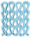 |  |  |
| S2 |  |  |  |
| S3 |  |  |  |
| S4 |  | 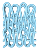 |  |
| Fabric No. | Thickness /mm | Surface Mass/ (g/m2) | Course Density/ (Wale/5 cm) | Wale Density/ (Course/5 cm) |
|---|---|---|---|---|
| S1 | 1.61 | 645.65 | 36 | 56 |
| S2 | 1.64 | 652.12 | 36 | 66 |
| S3 | 1.69 | 668.47 | 36 | 76 |
| S4 | 1.73 | 673.67 | 36 | 72 |
Disclaimer/Publisher’s Note: The statements, opinions and data contained in all publications are solely those of the individual author(s) and contributor(s) and not of MDPI and/or the editor(s). MDPI and/or the editor(s) disclaim responsibility for any injury to people or property resulting from any ideas, methods, instructions or products referred to in the content. |
© 2024 by the authors. Licensee MDPI, Basel, Switzerland. This article is an open access article distributed under the terms and conditions of the Creative Commons Attribution (CC BY) license (https://creativecommons.org/licenses/by/4.0/).
Share and Cite
Jiang, F.; Su, T.; Fang, L.; Zhao, K.; Cong, H. Structural Design and Performance of Cut-Resistant Fabrics with Concave–Convex Arrays. Polymers 2024, 16, 2137. https://doi.org/10.3390/polym16152137
Jiang F, Su T, Fang L, Zhao K, Cong H. Structural Design and Performance of Cut-Resistant Fabrics with Concave–Convex Arrays. Polymers. 2024; 16(15):2137. https://doi.org/10.3390/polym16152137
Chicago/Turabian StyleJiang, Fei, Ting Su, Leimei Fang, Kezheng Zhao, and Honglian Cong. 2024. "Structural Design and Performance of Cut-Resistant Fabrics with Concave–Convex Arrays" Polymers 16, no. 15: 2137. https://doi.org/10.3390/polym16152137