
Cryogenic Insulation—Towards Environmentally Friendly Polyurethane Foams


Abstract
:1. Introduction
2. Cryogenics and Cryogenic Rigid Polyurethane Foams from Commercially Available Polyols
3. Environmentally Friendly Blowing Agents in Cryogenic Rigid Polyurethane Foams
4. Bio-Based Polyols in Cryogenic Rigid Polyurethane Foams

| Components, pbw | |||||
|---|---|---|---|---|---|
| Low-functional rapeseed polyol | 0 | 5 | 10 | 15 | 20 |
| Diethylene glycol | 25 | 20 | 15 | 10 | 5 |
| Sustainable material content in PU foam, % | 16.1 | 17.3 | 18.7 | 19.9 | 21.3 |
| Thermal conductivity, mW/(m·K) | 18.7 | 18.9 | 20.1 | 21.4 | 27.5 |
| Closed-cell content, % | 97.5 | 92.0 | 91.0 | 88.0 | 78.0 |
| Safety coefficient | 2.5 | 1.7 | 1.1 | 1.1 | 1.0 |
- ε77—tensile elongation at 77 K, %;
- Δl77−300—shrinkage of material cooling it from 300 to 77 K, %;
- αx—coefficient of thermal expansion, 10−6/°C;
- ΔT—temperature gradient, degrees.
5. Concluding Remarks
Author Contributions
Funding
Conflicts of Interest
References
- DIRECTIVES DIRECTIVE (EU) 2018/2001 OF THE EUROPEAN PARLIAMENT AND OF THE COUNCIL of 11 December 2018 on the Promotion of the Use of Energy from Renewable Sources. Available online: https://eur-lex.europa.eu/legal-content/EN/TXT/PDF/?uri=CELEX:32018L2001 (accessed on 19 August 2024).
- Long-Term Aspirational Goal Overview of Climate Goals and ICAO’s Work on a Long-Term Aspirational Goal for International Aviation (LTAG) Overview of Climate Goals and ICAO’s Work on a Long-Term Aspirational Goal for International Aviation (LTAG) by ICAO Secretariat. Available online: https://www.icao.int/environmental-protection/Documents/EnvironmentalReports/2022/ENVReport2022_Special%20Supplement%20on%20LTAG.pdf (accessed on 19 August 2024).
- Fesmire, J.E. Standardization in Cryogenic Insulation Systems Testing and Performance Data. Phys. Procedia 2015, 67, 1089–1097. [Google Scholar] [CrossRef]
- Johnson, W.; Fesmire, J. Thermal Performance of Low Layer Density Multilayer Insulation Using Liquid Nitrogen. AIP Conf. Proc. 2012, 1434, 39–46. [Google Scholar]
- Xie, G.F.; Li, X.D.; Wang, R.S. Study on the Heat Transfer of High-Vacuum-Multilayer-Insulation Tank after Sudden, Catastrophic Loss of Insulating Vacuum. Cryogenics 2010, 50, 682–687. [Google Scholar] [CrossRef]
- Sun, P.J.; Wu, J.Y.; Zhang, P.; Xu, L.; Jiang, M.L. Experimental Study of the Influences of Degraded Vacuum on Multilayer Insulation Blankets. Cryogenics 2009, 49, 719–726. [Google Scholar] [CrossRef]
- Zheng, J.; Chen, L.; Cui, C.; Guo, J.; Zhu, W.; Zhou, Y.; Wang, J. Experimental Study on Composite Insulation System of Spray on Foam Insulation and Variable Density Multilayer Insulation. Appl. Therm. Eng. 2018, 130, 161–168. [Google Scholar] [CrossRef]
- Jiang, W.; Yang, Y.; Hu, C.; Li, P.; Sun, P.; Huang, Y. Experimental Study on Composite Insulation with Foam, Multilayer and Vapor Cooled Shield for Cryogen Storage under Different Vacuum Conditions. Cryogenics 2023, 129, 103604. [Google Scholar] [CrossRef]
- Ye, C.; Lin, Y.; Pei, F. Comparative Study of Three Insulation Materials Installed on Type C Independent Tank for Offshore LNG Transportation. Cryogenics 2022, 126, 103521. [Google Scholar] [CrossRef]
- Fesmire, J.E.; Ancipink, J.B.; Swanger, A.M.; White, S.; Yarbrough, D. Thermal Conductivity of Aerogel Blanket Insulation under Cryogenic-Vacuum Conditions in Different Gas Environments. In IOP Conference Series: Materials Science and Engineering, Proceedings of the Cryogenic Engineering Conference (CEC) 2017 (Previous Edition: CEC-2015), Madison, WI, USA, 9–13 July 2017; Institute of Physics Publishing: Bristol, UK, 2017; Volume 278. [Google Scholar]
- Global Hydrogen Review 2023. Available online: https://www.iea.org/reports/global-hydrogen-review-2023 (accessed on 11 July 2024).
- Ustolin, F.; Campari, A.; Taccani, R. An Extensive Review of Liquid Hydrogen in Transportation with Focus on the Maritime Sector. J. Mar. Sci. Eng. 2022, 10, 1222. [Google Scholar] [CrossRef]
- Adler, E.J.; Martins, J.R.R.A. Hydrogen-Powered Aircraft: Fundamental Concepts, Key Technologies, and Environmental Impacts. Prog. Aerosp. Sci. 2023, 141, 100922. [Google Scholar] [CrossRef]
- Verstraete, D.; Hendrick, P.; Pilidis, P.; Ramsden, K. Hydrogen Fuel Tanks for Subsonic Transport Aircraft. Int. J. Hydrogen Energy 2010, 35, 11085–11098. [Google Scholar] [CrossRef]
- Winnefeld, C.; Kadyk, T.; Bensmann, B.; Krewer, U.; Hanke-Rauschenbach, R. Modelling and Designing Cryogenic Hydrogen Tanks for Future Aircraft Applications. Energies 2018, 11, 105. [Google Scholar] [CrossRef]
- Huete, J.; Pilidis, P. Parametric Study on Tank Integration for Hydrogen Civil Aviation Propulsion. Int. J. Hydrogen Energy 2021, 46, 37049–37062. [Google Scholar] [CrossRef]
- Kameni Monkam, L.; Graf von Schweinitz, A.; Friedrichs, J.; Gao, X. Feasibility Analysis of a New Thermal Insulation Concept of Cryogenic Fuel Tanks for Hydrogen Fuel Cell Powered Commercial Aircraft. Int. J. Hydrogen Energy 2022, 47, 31395–31408. [Google Scholar] [CrossRef]
- Alkhaledi, A.N.F.N.R.; Sampath, S.; Pilidis, P. A Hydrogen Fuelled LH2 Tanker Ship Design. Ships Offshore Struct. 2022, 17, 1555–1564. [Google Scholar] [CrossRef]
- Kang, D.; Yun, S.; Kim, B.K. Review of the Liquid Hydrogen Storage Tank and Insulation System for the High-Power Locomotive. Energies 2022, 15, 4357. [Google Scholar] [CrossRef]
- Lebrun, P. Introduction to Cryogenics Cryogenic Fluids. In Proceedings of the CAS 2006—CERN Accelerator School: Vacuum in Accelerators, Proceedings, Platja d’Aro, Spain, 16–24 May 2006; pp. 15–30. [Google Scholar]
- Daunt, J.G. Cryogenics. Phys. Today 1962, 15, 26–28. [Google Scholar] [CrossRef]
- International Institute of Refrigeration International Dictionary of Refrigeration. Available online: https://dictionary.iifiir.org/index.php (accessed on 3 May 2024).
- Anthony, F.M.; Colt, J.Z.; Helenbrook, R.G. Development and Validation of Cryogenic Foam Insulation for LH2 Subsonic Transports; NASA: Washington, DC, USA, 1981.
- Peschka, W. Thermal Insulation, Storage and Transportation of Liquid Hydrogen. In Liquid Hydrogen; Spring: Vienna, Austria, 1992. [Google Scholar]
- Colozza, A.J. Hydrogen Storage for Aircraft; Analex Corporation: Brook Park, OH, USA, 2002; ISBN 3016210134. [Google Scholar]
- Musgrave, D.S. Thermal Performance of Urethane Pipe Insulation at Cryogenic Temperatures. J. Therm. Insul. 1979, 3, 3–21. [Google Scholar] [CrossRef]
- Darkow, N.; Fischer, A.; Scheufler, H.; Hellmann, H.; Gerstmann, J. Concept Development of a Cryogenic Tank Insulation for Reusable Launch Vehicle. In Proceedings of the 8th European Conference for Aeronautics and Space Sciences (EUCASS), Madrid, Spain, 1–4 July 2019. [Google Scholar] [CrossRef]
- Sullivan, R.M.; Palko, J.L.; Tornabene, R.T.; Bednarcyk, B.A.; Powers, L.M.; Smith, L.M.; Wang, X.J.; Hunter, J.E. Engineering Analysis Studies for Preliminary Design of Lightweight Cryogenic Hydrogen Tanks in UAV Applications; NASA: Washington, DC, USA, 2006.
- Mital, S.K.; Gyekenyesi, J.Z.; Arnold, S.M.; Sullivan, R.M.; Manderscheid, J.M.; Murthy, P.L.N. Review of Current State of the Art and Key Design Issues with Potential Solutions for Liquid Hydrogen Cryogenic Storage Tank Structures for Aircraft Applications; Nasa-Tm-2006-214346; NASA: Washington, DC, USA, 2006; pp. 3–21.
- Ten, C.L. Advances in Heat Transfer; Elsevier: Amsterdam, The Netherlands, 1974; Volume 10. [Google Scholar]
- Fesmire, J.E.; Coffman, B.E.; Meneghelli, B.J.; Heckle, K.W. Spray-on Foam Insulations for Launch Vehicle Cryogenic Tanks. Cryogenics 2012, 52, 251–261. [Google Scholar] [CrossRef]
- Tien, C.L.; Cunnington, G.R. Glass Microsphere Cryogenic Insulation. Cryogenics 1976, 16, 583–586. [Google Scholar] [CrossRef]
- Ratnakar, R.R.; Sun, Z.; Balakotaiah, V. Effective Thermal Conductivity of Insulation Materials for Cryogenic LH2 Storage Tanks: A Review. Int. J. Hydrogen Energy 2023, 48, 7770–7793. [Google Scholar] [CrossRef]
- Dearing, D.L. Development of the Saturn S-IV and S-IVB Liquid Hydrogen Tank Internal Insulation. In Advances in Cryogenic Engineering; Springer: Boston, MA, USA, 1966; pp. 89–97. [Google Scholar] [CrossRef]
- Bauer, H.E. Operational Experiences on the Saturn V S-IVB Stage; SAE Technical Papers; SAE: Warrendale, PA, USA, 1968. [Google Scholar] [CrossRef]
- Lemons, C.R.; Watts, C.R.; Salmassy, O.K. Development of Advanced Materials Composites for Use as Insulations LH2 Tanks. Angew. Chem. Int. Ed. 2019, 6, 951–952. [Google Scholar]
- Li, K.; Wu, Z.; Liu, M.; Xu, X.; Xu, W. An Application of Reinforced Polyurethane Foam in Design of the Common Bulkhead for Cryogenic Tanks. Mater. Sci. Forum 2020, 975, 182–187. [Google Scholar] [CrossRef]
- Lee, D.H.; Ha, M.K.; Kim, S.Y.; Shin, S.C. Research of Design Challenges and New Technologies for Floating LNG. Int. J. Nav. Archit. Ocean. Eng. 2014, 6, 307–322. [Google Scholar] [CrossRef]
- Oh, D.J.; Lee, J.M.; Chun, M.S.; Kim, M.H. Reliability Evaluation of a LNGC Insulation System with a Metallic Secondary Barrier. Compos. Struct. 2017, 171, 43–52. [Google Scholar] [CrossRef]
- Huan, T.; Hongjun, F.; Wei, L.; Guoqiang, Z. Options and Evaluations on Propulsion Systems of LNG Carriers. In Propulsion Systems; IntechOpen: London, UK, 2019. [Google Scholar] [CrossRef]
- Kim, J.H.; Kim, S.K.; Kim, M.S.; Lee, J.M. Numerical Simulation of Membrane Og LNG Insulation System Using User Defined Material Subroutine. J. Comput. Struct. Eng. Inst. Korea 2014, 27, 265–271. [Google Scholar]
- Hwang, B.K.; Kim, S.K.; Kim, J.H.; Kim, J.D.; Lee, J.M. Dynamic Compressive Behavior of Rigid Polyurethane Foam with Various Densities under Different Temperatures. Int. J. Mech. Sci. 2020, 180, 105657. [Google Scholar] [CrossRef]
- Yu, Y.H.; Choi, I.; Nam, S.; Lee, D.G. Cryogenic Characteristics of Chopped Glass Fiber Reinforced Polyurethane Foam. Compos. Struct. 2014, 107, 476–481. [Google Scholar] [CrossRef]
- Park, S.B.; Choi, S.W.; Kim, J.H.; Bang, C.S.; Lee, J.M. Effect of the Blowing Agent on the Low-Temperature Mechanical Properties of CO2- and HFC-245fa-Blown Glass-Fiber-Reinforced Polyurethane Foams. Compos. B Eng. 2016, 93, 317–327. [Google Scholar] [CrossRef]
- Song, C.Y.; Cho, D.Y. Cryogenic Compressive Strength and Thermal Deformation of Reinforced Polyurethane Foam Material for Membrane Type LNG Carrier. In Proceedings of the Key Engineering Materials; Trans Tech Publications Ltd.: Wollerau, Switzerland, 2018; Volume 773, pp. 30–39. [Google Scholar]
- Song, H.-C. Assessment of Cryogenic Material Properties of R-PUF Used in the CCS of an LNG Carrier. J. Ocean. Eng. Technol. 2022, 36, 217–231. [Google Scholar] [CrossRef]
- Kim, J.D.; Kim, J.H.; Lee, D.H.; Yeom, D.J.; Lee, J.M. Synthesis and Investigation of Cryogenic Mechanical Properties of Chopped-Glass-Fiber-Reinforced Polyisocyanurate Foam. Materials 2021, 14, 446. [Google Scholar] [CrossRef]
- Park, S.B.; Lee, C.S.; Choi, S.W.; Kim, J.H.; Bang, C.S.; Lee, J.M. Polymeric Foams for Cryogenic Temperature Application: Temperature Range for Non-Recovery and Brittle-Fracture of Microstructure. Compos. Struct. 2016, 136, 258–269. [Google Scholar] [CrossRef]
- Kim, J.-H.; Kim, S.-K.; Park, S.; Hyun Park, K.; Lee, J.-M. Low-Temperature Mechanical Behavior of Reinforced Polyurethane Foam. Int. J. Mech. Eng. 2017, 2, 15–18. [Google Scholar]
- Park, K.B.; Kim, H.T.; Her, N.Y.; Lee, J.M. Variation of Mechanical Characteristics of Polyurethane Foam: Effect of Test Method. Materials 2019, 12, 2672. [Google Scholar] [CrossRef] [PubMed]
- Chun, M.S.; Kim, M.H.; Kim, W.S.; Kim, S.H.; Lee, J.M. Experimental Investigation on the Impact Behavior of Membrane-Type LNG Carrier Insulation System. J. Loss Prev. Process Ind. 2009, 22, 901–907. [Google Scholar] [CrossRef]
- Yu, Y.H.; Nam, S.; Lee, D.; Lee, D.G. Cryogenic Impact Resistance of Chopped Fiber Reinforced Polyurethane Foam. Compos. Struct. 2015, 132, 12–19. [Google Scholar] [CrossRef]
- Oh, J.H.; Bae, J.H.; Kim, J.H.; Lee, C.S.; Lee, J.M. Effects of Kevlar Pulp on the Enhancement of Cryogenic Mechanical Properties of Polyurethane Foam. Polym. Test. 2019, 80, 106093. [Google Scholar] [CrossRef]
- Kim, J.H.; Kim, J.M.; Park, S.; Park, K.H.; Lee, J.M. Synthesis and Cryogenic Mechanical Properties of CO2-Blown Carbon-Reinforced Polyurethane Foam. J. Cell. Plast. 2018, 54, 743–763. [Google Scholar] [CrossRef]
- Park, J.H.; Oh, D.J.; Kim, M.H.; Kim, K.H.; Kim, M.K.; Moon, H.S. Fatigue Strength of a LNGC Secondary Barrier Made of a Composite Material with Aramid Fibers. Mech. Compos. Mater. 2018, 54, 431–442. [Google Scholar] [CrossRef]
- Yu, Y.H.; Kim, B.G.; Lee, D.G. Cryogenic Reliability of the Sandwich Insulation Board for LNG Ship. Compos. Struct. 2013, 95, 547–556. [Google Scholar] [CrossRef]
- Yu, Y.H.; Kim, B.G.; Lee, D.G. Cryogenic Reliability of Composite Insulation Panels for Liquefied Natural Gas (LNG) Ships. Compos. Struct. 2012, 94, 462–468. [Google Scholar] [CrossRef]
- Lee, C.S.; Lee, J.M. Failure Analysis of Reinforced Polyurethane Foam-Based LNG Insulation Structure Using Damage-Coupled Finite Element Analysis. Compos. Struct. 2014, 107, 231–245. [Google Scholar] [CrossRef]
- Soumya Chakraborty Understanding the Design of Liquefied Gas Carriers. Available online: https://www.marineinsight.com/naval-architecture/understanding-design-liquefied-gas-carriers/ (accessed on 11 July 2024).
- Giannopoulos, I.K.; Theotokoglou, E.E. Liquid Hydrogen Storage Tank Loading Generation for Civil Aircraft Damage Tolerance Analysis. In Proceedings of the Journal of Physics: Conference Series; Institute of Physics: London, UK, 2024; Volume 2692, p. 012048. [Google Scholar]
- Yatsenko, E.A.; Goltsman, B.M.; Novikov, Y.V.; Izvarin, A.I.; Rusakevich, I.V. Review on Modern Ways of Insulation of Reservoirs for Liquid Hydrogen Storage. Int. J. Hydrogen Energy 2022, 47, 41046–41054. [Google Scholar] [CrossRef]
- Mack, F.E.; Smith, M.E. High-Performance Spray-Foam Insulation for Application on Saturn S-II Stage*. Available online: https://ntrs.nasa.gov/citations/19710058573 (accessed on 3 May 2024).
- McCutcheon, K.D. U.S. Manned Rocket Propulsion Evolution. Part 8.20: The Saturn V S-II Stage. Available online: https://www.enginehistory.org/Rockets/RPE08.20/RPE08.20.shtml (accessed on 3 May 2024).
- Mike Jetzer The Apollo Flight Journal. S-II Insulation. Available online: https://www.nasa.gov/history/afj/s-ii/s-ii-insulation.html (accessed on 3 May 2024).
- Bilstein, R.E. Stages to Saturn: A Technological History of the Apollo/Saturn Launch Vehicles. NASA SP-4206. Available online: https://ntrs.nasa.gov/citations/19970009949 (accessed on 3 May 2024).
- Gusev, Y.; Kolozezny, A.; Panichkin, N.; Volkov, N. Cryogenic Thermal Insulation Based on PUF for Tank…. In Proceedings of the 56th International Astronautical Congress of the International Astronautical Federation, the International Academy of Astronautics, and the International Institute of Space Law, Fukuoka, Japan, 1–21 October 2005; American Institute of Aeronautics and Astronautics: Reston, VA, USA, 2005. [Google Scholar]
- Gray, C.; Ronquillo, L.; Williams, C. Spray-on Foam Insulation Development for the Space Shuttle External Tank Thermal Protection System; SAE International: Warrendale, PA, USA, 1984. [Google Scholar]
- Gates, T.S.; Johnson, T.F.; Whitley, K.S. Assessment of Technologies for the Space Shuttle External Tank Thermal Protection System and Recommendations for Technology Improvement Part 3: Material Property Characterization, Analysis, and Test Methods; Langley Reserch Center: Hampton, VA, USA, 2005. [Google Scholar]
- Columbia Accident Investigation Board. Report Volume 1. Chapter 3. Accident Analysis. Available online: https://www.globalsecurity.org/space/library/report/2003/caib-report_vol1_chapter3.pdf (accessed on 3 May 2024).
- Sullivan, R.M.; Lerch, B.A.; Rogers, P.R.; Sparks, J.S. An Overview of Spray-On Foam Insulation Applications on the Space Shuttle’s External Tank: Foam Applications and Foam Shedding Mechanisms; Mechanisms 43rd Annual Technical Meeting of the Society of Engineering Science 2006. Available online: https://ntrs.nasa.gov/api/citations/20070008105/downloads/20070008105.pdf (accessed on 3 May 2024).
- Dreggors, K. Alternative Foam Treatments for The Space Shuttle’s External Tank. 2005. Available online: https://stars.library.ucf.edu/etd/548/?utm_source=stars.library.ucf.edu%2Fetd%2F548&utm_medium=PDF&utm_campaign=PDFCoverPages (accessed on 3 May 2024).
- Sharpe, E.L. Durability of Foam Insulation for LH2 Fuel Tanks of Future Subsonic Transports. In Nonmetallic Materials and Composites at Low Temperatures; Cryogenic Materials Series; Clark, A.F., Reed, R.P., Hartwig, G., Eds.; Springer: Boston, MA, USA, 1979. [Google Scholar]
- Cunnington, G.R.; Lockheed Palo, J.R. Insulation Systems for Liquid Hydrogen Fueled Aircraft. J. Therm. Insul. 1980, 4, 61–79. [Google Scholar] [CrossRef]
- Brewer, G.D. Hydrogen Aircraft Technology, 1st ed.; Routledge: New York, NY, USA, 2017. [Google Scholar]
- Wilken, J.; Callsen, S.; Daub, D.; Fischer, A.; Liebisch, M.; Rauh, C.; Reimer, T.; Scheufler, H.; Sippel, M. Combined Cryogenic Insulation and Thermal Protection Systems for Reusable Stages. In Proceedings of the 9th European Conference for Aeronautics and Space Sciences (EUCASS), Lille, France, 27 June–1 July 2023. [Google Scholar] [CrossRef]
- Sharifzadeh, S.; Verstraete, D.; Hendrick, P. Cryogenic Hydrogen Fuel Tanks for Large Hypersonic Cruise Vehicles. Int. J. Hydrogen Energy 2015, 40, 12798–12810. [Google Scholar] [CrossRef]
- The Montreal Protocol. Available online: https://www.unep.org/ozonaction/who-we-are/about-montreal-protocol (accessed on 17 May 2024).
- The Kyoto Protocol. Available online: https://unfccc.int/kyoto_protocol (accessed on 17 May 2024).
- Poulopoulos, S.G. Atmospheric Environment. In Environment and Development; Elsevier: Amsterdam, The Netherlands, 2016; pp. 45–136. [Google Scholar]
- Regulation (EU) No. 517/2014 of the European Parliament and of the Council on Fluorinated Greenhouse Gases and Repealing Regulation (EC) No. 842/2006. Available online: https://www.fao.org/faolex/results/details/en/c/LEX-FAOC133686/#:~:text=European%20Union-,Regulation%20(EU)%20No.,emissions%20of%20fluorinated%20greenhouse%20gases (accessed on 17 May 2024).
- Methylal as Blowing Agent in the Manufacture of Polyurethane Foam Systems. Available online: http://multilateralfund.org/Our%20Work/DemonProject/Document%20Library/6617p5%20methylal%20PU%20foam.pdf (accessed on 17 May 2024).
- Opteon TM 1100 Foam Blowing Agent Product Information. Available online: https://www.opteon.com/en/-/media/files/opteon/opteon-1100-data-sheet.pdf?la=en& (accessed on 17 May 2024).
- Blowing Agents Solstice Liquid Blowing Agent TECHNICAL INFORMATION. Available online: https://prod-edam.honeywell.com/content/dam/honeywell-edam/pmt/oneam/en-us/blowing-agents/documents/pmt-am-solstice-lba-datasheet.pdf (accessed on 17 May 2024).
- Ecomate. Available online: https://ecomatetechnology.com/ (accessed on 17 May 2024).
- Yakushin, V.; Cabulis, U.; Fridrihsone, V.; Kravchenko, S.; Pauliks, R. Properties of Polyurethane Foam with Fourth-Generation Blowing Agent. E-Polymers 2021, 21, 763–769. [Google Scholar] [CrossRef]
- Yakushin, V.; Rundans, M.; Holynska, M.; Sture, B.; Cabulis, U. Influence of Reactive Amine-Based Catalysts on Cryogenic Properties of Rigid Polyurethane Foams for Space and On-Ground Applications. Materials 2023, 16, 2798. [Google Scholar] [CrossRef]
- Sture, B.; Yakushin, V.; Vevere, L.; Cabulis, U. Influence of Long-Term Storage and UV Light Exposure on Characteristics of Polyurethane Foams for Cryogenic Insulation. Materials 2023, 16, 7071. [Google Scholar] [CrossRef]
- Casati, F.M.; Sonney, J.M.; Mispreuve, H.; Fanget, A.; Herrington, R.; Tu, J. Elimination of Amine Emissions from Polyurethane Foams: Challenges and Opportunities. In Polyurethanes Expo 2001; CRC Press: Boca Raton, FL, USA, 2020; pp. 47–58. [Google Scholar]
- Sikorski, M.; Wehman, C.; Cordelair, H. New Additive Solutions for Low VOC in HR Molded Foams. J. Cell. Plast. 2000, 36, 294–309. [Google Scholar] [CrossRef]
- Pretti, C.; Oliva, M.; Mennillo, E.; Barbaglia, M.; Funel, M.; Reddy Yasani, B.; Martinelli, E.; Galli, G. An Ecotoxicological Study on Tin- and Bismuth-Catalysed PDMS Based Coatings Containing a Surface-Active Polymer. Ecotoxicol. Environ. Saf. 2013, 98, 250–256. [Google Scholar] [CrossRef]
- Park, J.S.; Kim, H.T.; Kim, J.D.; Kim, J.H.; Kim, S.K.; Lee, J.M. Eco-Friendly Blowing Agent, HCFO-1233zd, for the Synthesis of Polyurethane Foam as Cryogenic Insulation. J. Appl. Polym. Sci. 2022, 139, 51492. [Google Scholar] [CrossRef]
- Vevere, L.; Arshanitsa, A.; Telysheva, G. The Oxypropylation of Residual Grey Alder Bark as a Tool for Realisation of Biorefinery Concept. p. 72. Available online: https://alephfiles.rtu.lv/TUA01/000047431_e.pdf (accessed on 10 July 2024).
- Arshanitsa, A.; Ponomarenko, J.; Pals, M.; Jashina, L. Controlling the Reactivity of Hydrophilic Bark Extractives as Biopolyols in Urethane-Formation Reactions Using Various Catalysts. Ind. Crops Prod. 2023, 204, 117385. [Google Scholar] [CrossRef]
- Arshanitsa, A.; Ponomarenko, J.; Pals, M.; Jashina, L.; Lauberts, M. Impact of Bark-Sourced Building Blocks as Substitutes for Fossil-Derived Polyols on the Structural, Thermal, and Mechanical Properties of Polyurethane Networks. Polymers 2023, 15, 3503. [Google Scholar] [CrossRef] [PubMed]
- Vevere, L.; Janceva, S.; Arshanitsa, A.; Telysheva, G. Polyols from Condensed Tannin Enriched Extracts for Rigid Polyurethane Foam. Key Eng. Mater. 2018, 762, 197–202. [Google Scholar] [CrossRef]
- Olszewski, A.; Kosmela, P.; Vēvere, L.; Kirpluks, M.; Cabulis, U.; Piszczyk, Ł. Effect of Bio-Polyol Molecular Weight on the Structure and Properties of Polyurethane-Polyisocyanurate (PUR-PIR) Foams. Sci. Rep. 2024, 14, 812. [Google Scholar] [CrossRef] [PubMed]
- Ivdre, A.; Kirpluks, M.; Abolins, A.; Vevere, L.; Sture, B.; Paze, A.; Godina, D.; Rizikovs, J.; Cabulis, U. Rigid Polyurethane Foams’ Development and Optimization from Polyols Based on Depolymerized Suberin and Tall Oil Fatty Acids. Polymers 2024, 16, 942. [Google Scholar] [CrossRef] [PubMed]
- Ivdre, A.; Abolins, A.; Volkovs, N.; Vevere, L.; Paze, A.; Makars, R.; Godina, D.; Rizikovs, J. Rigid Polyurethane Foams as Thermal Insulation Material from Novel Suberinic Acid-Based Polyols. Polymers 2023, 15, 3124. [Google Scholar] [CrossRef]
- Mazar, A.; Paleologou, M. New Approach to Recycle and Valorize the First Filtrate of the LignoForce SystemTM: Lignin Extraction and Its Use in Rigid Lignin-Based Polyurethane Foams. Int. J. Biol. Macromol. 2023, 244, 125346. [Google Scholar] [CrossRef]
- Du, J.; Wang, H.; Huang, Z.; Liu, X.; Yin, X.; Wu, J.; Lin, W.; Lin, X.; Yi, G. Construction and Mechanism Study of Lignin-Based Polyurethane with High Strength and High Self-Healing Properties. Int. J. Biol. Macromol. 2023, 248, 125925. [Google Scholar] [CrossRef]
- Huang, Z.; Wang, H.; Du, J.; Liu, X.; Pan, G.; Yin, X.; Lin, W.; Lin, X.; Sun, Y.; Yi, G.; et al. High-Strength, Self-Reinforcing and Recyclable Multifunctional Lignin-Based Polyurethanes Based on Multi-Level Dynamic Cross-Linking. Chem. Eng. J. 2023, 473, 145423. [Google Scholar] [CrossRef]
- Ajao, O.; Benali, M.; Faye, A.; Li, H.; Maillard, D.; Ton-That, M.T. Multi-Product Biorefinery System for Wood-Barks Valorization into Tannins Extracts, Lignin-Based Polyurethane Foam and Cellulose-Based Composites: Techno-Economic Evaluation. Ind. Crops Prod. 2021, 167, 113435. [Google Scholar] [CrossRef]
- Wang, J.; Yao, K.; Korich, A.L.; Li, S.; Ma, S.; Ploehn, H.J.; Iovine, P.M.; Wang, C.; Chu, F.; Tang, C. Combining Renewable Gum Rosin and Lignin: Towards Hydrophobic Polymer Composites by Controlled Polymerization. J. Polym. Sci. A Polym. Chem. 2011, 49, 3728–3738. [Google Scholar] [CrossRef]
- Arshanitsa, A.; Vevere, L.; Telysheva, G.; Dizhbite, T.; Gosselink, R.J.; Bikovens, O.; Jablonski, A. Functionality and Physico-Chemical Characteristics of Wheat Straw Lignin, BioligninTM, Derivatives Formed in the Oxypropylation Process. Holzforschung 2015, 69, 785–793. [Google Scholar] [CrossRef]
- Arshanitsa, A.; Paberza, A.; Vevere, L.; Cabulis, U.; Telysheva, G. Two Approaches for Introduction of Wheat Straw Lignin into Rigid Polyurethane Foams. In Proceedings of the AIP Conference Proceedings; American Institute of Physics Inc.: College Park, MD, USA, 2014; Volume 1593, pp. 388–391. [Google Scholar]
- Kurańska, M.; Pinto, J.A.; Salach, K.; Barreiro, M.F.; Prociak, A. Synthesis of Thermal Insulating Polyurethane Foams from Lignin and Rapeseed Based Polyols: A Comparative Study. Ind. Crops Prod. 2020, 143, 111882. [Google Scholar] [CrossRef]
- Lavazza, J.; Zhang, Q.; de Kergariou, C.; Comandini, G.; Briscoe, W.H.; Rowlandson, J.L.; Panzera, T.H.; Scarpa, F. Rigid Polyurethane Foams from Commercial Castor Oil Resins. Polym. Test. 2024, 135, 108457. [Google Scholar] [CrossRef]
- Samranrit, T.; Ngernsombat, K.; Ritthisorn, S.; Teeka, J.; Chiu, C.H.; Reungsang, A.; Areesirisuk, A. Sustainable Production of Yeast Oil from Rice Straw Hydrolysate by Pseudozyma Parantarctica through Fed-Batch Cultivation for Bio-Polyurethane Foam Formation. Bioresour. Technol. Rep. 2024, 27, 101892. [Google Scholar] [CrossRef]
- Luo, X.; Xiao, Y.; Wu, Q.; Zeng, J. Development of High-Performance Biodegradable Rigid Polyurethane Foams Using All Bioresource-Based Polyols: Lignin and Soy Oil-Derived Polyols. Int. J. Biol. Macromol. 2018, 115, 786–791. [Google Scholar] [CrossRef]
- Fan, X.; Wang, H.; Kong, L.; Huang, J. Advanced Ethylene-Absorbing and Cushioning Depending on the 3D Porous-Structured Fruit Packaging: Toward Polyurethane Foam Manipulation Using Zein and Soybean Oil Polyol Substrates. Food Res. Int. 2024, 186, 114340. [Google Scholar] [CrossRef]
- Ivdre, A.; Soto, G.D.; Cabulis, U. Polyols Based on Poly(Ethylene Terephthalate) and Tall Oil: Perspectives for Synthesis and Production of Rigid Polyurethane Foams. J. Renew. Mater. 2016, 4, 285–293. [Google Scholar] [CrossRef]
- Pietrzak, K.; Kirpluks, M.; Cabulis, U.; Ryszkowska, J. Effect of the Addition of Tall Oil-Based Polyols on the Thermal and Mechanical Properties of Ureaurethane Elastomers. Polym. Degrad. Stab. 2014, 108, 201–211. [Google Scholar] [CrossRef]
- Polaczek, K.; Kaulina, E.; Pomilovskis, R.; Fridrihsone, A.; Kirpluks, M. Epoxidation of Tall Oil Fatty Acids and Tall Oil Fatty Acids Methyl Esters Using the SpinChem® Rotating Bed Reactor. J. Polym. Environ. 2022, 30, 4774–4786. [Google Scholar] [CrossRef]
- Vanags, E.; Kirpluks, M.; Cabulis, U.; Walterova, Z. Highly Functional Polyol Synthesis from Epoxidized Tall Oil Fatty Acids. J. Renew. Mater. 2018, 6, 764–771. [Google Scholar] [CrossRef]
- Abolins, A.; Pomilovskis, R.; Vanags, E.; Mierina, I.; Michalowski, S.; Fridrihsone, A.; Kirpluks, M. Impact of Different Epoxidation Approaches of Tall Oil Fatty Acids on Rigid Polyurethane Foam Thermal Insulation. Materials 2021, 14, 894. [Google Scholar] [CrossRef] [PubMed]
- Andersons, J.; Grūbe, R.; Vēvere, L.; Cābulis, P.; Kirpluks, M. Anisotropic Thermal Expansion of Bio-Based Rigid Low-Density Closed-Cell Polyurethane Foams. J. Mater. Res. Technol. 2022, 16, 1517–1525. [Google Scholar] [CrossRef]
- Qin, Z.H.; Fridrihsone, A.; Mou, J.H.; Pomilovskis, R.; Godina, D.; Miao, Y.; Liu, Z.; Tsang, C.W.; Zhang, L.; Xu, C.; et al. Valorisation of Food Waste into Bio-Based Polyurethane Rigid Foams: From Experimental Investigation to Techno-Economic Analysis. Chem. Eng. J. 2024, 493, 152680. [Google Scholar] [CrossRef]
- Cardolite Inc. Home Page. Available online: https://www.cardolite.com/ (accessed on 19 August 2024).
- Polylabs Ltd. Home Page. Available online: https://www.polylabs.eu/ (accessed on 19 August 2024).
- Uram, K.; Prociak, A.; Vevere, L.; Pomilovskis, R.; Cabulis, U.; Kirpluks, M. Natural Oil-Based Rigid Polyurethane Foam Thermal Insulation Applicable at Cryogenic Temperatures. Polymers 2021, 13, 4276. [Google Scholar] [CrossRef]
- Sture, B.; Vevere, L.; Kirpluks, M.; Godina, D.; Fridrihsone, A.; Cabulis, U. Polyurethane Foam Composites Reinforced with Renewable Fillers for Cryogenic Insulation. Polymers 2021, 13, 4089. [Google Scholar] [CrossRef]
- Yakushin, V.; Stirna, U.; Bel’kova, L.; Deme, L.; Sevastyanova, I. Properties of Rigid Polyurethane Foams Filled with Milled Carbon Fibers. Mech. Compos. Mater. 2011, 46, 679–688. [Google Scholar] [CrossRef]
- Moon, R.J.; Martini, A.; Nairn, J.; Simonsen, J.; Youngblood, J. Cellulose Nanomaterials Review: Structure, Properties and Nanocomposites. Chem. Soc. Rev. 2011, 40, 3941. [Google Scholar] [CrossRef]
- Siró, I.; Plackett, D. Microfibrillated Cellulose and New Nanocomposite Materials: A Review. Cellulose 2010, 17, 459–494. [Google Scholar] [CrossRef]
- Vevere, L.; Sture, B.; Yakushin, V.; Kirpluks, M.; Cabulis, U. Bio-Based Rigid Polyurethane Foams for Cryogenic Insulation. J. Renew. Mater. 2024, 12, 585–602. [Google Scholar] [CrossRef]


| Vacuum MLI | Aerogels | Rigid PU Foams |
|---|---|---|
| + Low thermal conductivity | + Lightweight + Quiet low thermal conductivity | + Easy to apply + Can cover any shape and form, including connection points + Lightweight + Good mechanical properties + Moisture stable + In the case of damage, it is easily fixed |
| - Heavier - In the case of damage, it loses insulation properties | - Sensitive to moisture - Often quite fragile | - Some may have problems with cryo-pumping - Higher thermal conductivity than MLI and aerogels |
| Material Number | Foam Type | Function | Blowing Agent |
|---|---|---|---|
| NCFI 24–124 | Polyisocyanurate | Insulation | HCFH 141b |
| NCFI 24–57 | Polyisocyanurate | Insulation | HCFH 141b |
| BX-250 | Polyurethane | Insulation | CFC-11 |
| BX-265 | Polyurethane | Insulation | HCFH 141b |
| MA-25 | Elastomeric silicone | Ablator | N/A |
| SLA-561 | Cork-filled elastomeric silicone | Ablator | N/A |
| PDL-1034 | Urethane | Repairs | N/A |
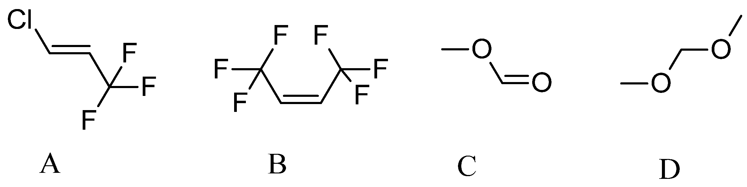
| Chemical Name | trans-1-Chloro-3,3,3-trifluoropropene | tis-1,1,1,4,4,4-Hexafluoro-2-butene | Dimethoxy Methane | Methyl Formate |
|---|---|---|---|---|
| CAS number | 102687-65-0 | 692-49-9 | 109-87-5 | 107-31-3 |
| Molecular weight, g/mol | 130.5 | 164.1 | 76.0 | 60.1 |
| Boiling point, °C | 18.6 | 33.4 | 42.0 | 32.0 |
| Freezing point, °C | <−90.0 | −90.5 | −105.0 | −100.0 |
| Global warming potential | 1 | 2 | Negligible | 0 |
| Ozone depletion potential | 0 | 0 | 0 | 0 |
| Name | Origin | OHvalue, mgKOH/g | Acid Value, mgKOH/g | Average Functionality |
|---|---|---|---|---|
| TT | Tall oil | 295 | <5 | 2.4 |
| TD | Tall oil | 271 | 1.8 | 2.2 |
| RD | Rapeseed oil | 394 | 4.8 | 3.5 |
| GX-9006 | Cashew nutshell | 201 | <0.2 | 4.4 |
| GX-9101 | Cashew nutshell | 430 | 2.8 | 3.0 |
| GX-9104 | Cashew nutshell | 235 | 0.11 | 3.0 |
| NX-9001 | Cashew nutshell | 193 | <0.2 | 4.3 |
| NX-9004 | Cashew nutshell | 193 | <0.2 | 3.8 |
| Components, pbw | ||||
|---|---|---|---|---|
| Filler | - | Sawdust | Microcelullose | Nanocellulose |
| Sustainable material content in PU foam, % | n.a. | n.a. | n.a. | n.a. |
| Thermal conductivity, mW/(m·K) | 18.7 | 17.7 | 18.5 | 18.1 |
| Closed-cell content, % | n.a. | n.a. | n.a. | n.a. |
| Safety coefficient | 2.7 | 2.2 | 2.3 | |
Disclaimer/Publisher’s Note: The statements, opinions and data contained in all publications are solely those of the individual author(s) and contributor(s) and not of MDPI and/or the editor(s). MDPI and/or the editor(s) disclaim responsibility for any injury to people or property resulting from any ideas, methods, instructions or products referred to in the content. |
© 2024 by the authors. Licensee MDPI, Basel, Switzerland. This article is an open access article distributed under the terms and conditions of the Creative Commons Attribution (CC BY) license (https://creativecommons.org/licenses/by/4.0/).
Share and Cite
Vevere, L.; Yakushin, V.; Sture-Skela, B.; Andersons, J.; Cabulis, U. Cryogenic Insulation—Towards Environmentally Friendly Polyurethane Foams. Polymers 2024, 16, 2406. https://doi.org/10.3390/polym16172406
Vevere L, Yakushin V, Sture-Skela B, Andersons J, Cabulis U. Cryogenic Insulation—Towards Environmentally Friendly Polyurethane Foams. Polymers. 2024; 16(17):2406. https://doi.org/10.3390/polym16172406
Chicago/Turabian StyleVevere, Laima, Vladimir Yakushin, Beatrise Sture-Skela, Janis Andersons, and Ugis Cabulis. 2024. "Cryogenic Insulation—Towards Environmentally Friendly Polyurethane Foams" Polymers 16, no. 17: 2406. https://doi.org/10.3390/polym16172406