
The Influence of Oil and Thermal Aging on the Sealing Characteristics of NBR Seals

Abstract
:1. Introduction
2. Materials and Methods
2.1. Materials
2.2. Aging Testing
2.3. Hardness Testing
2.4. Compression Testing
2.5. Friction Testing
2.6. Finite Element Model of Seals
2.6.1. Material Constitutive Model
2.6.2. Meshing
2.6.3. Boundary and Load Condition
- (1)
- The shaft was held stationary while the groove was displaced. The aim at this stage was to achieve a 13% compression of the O-ring for a pre-compression process.
- (2)
- The displacement was further applied to the grooves until the assembly requirements were met for the subsequent application of oil pressure.
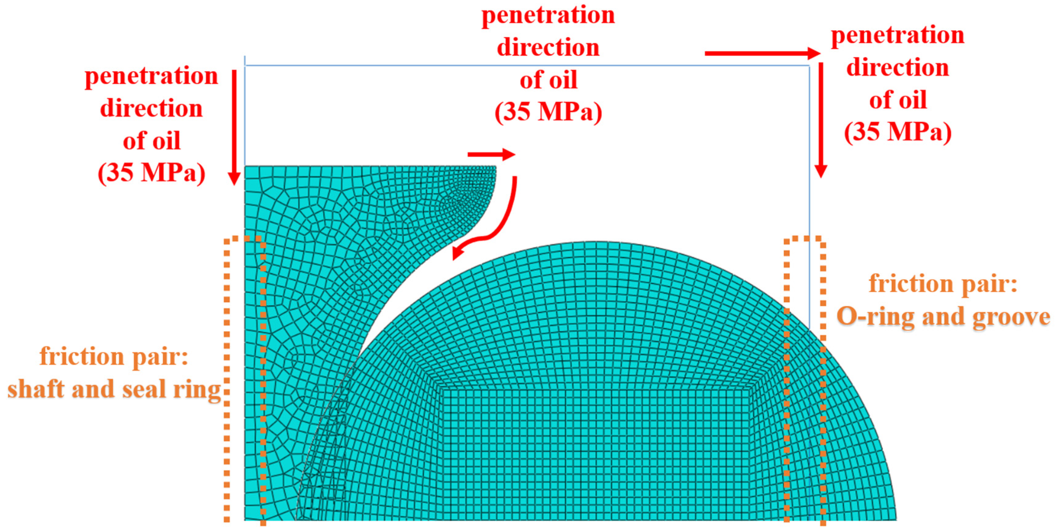
- (3)
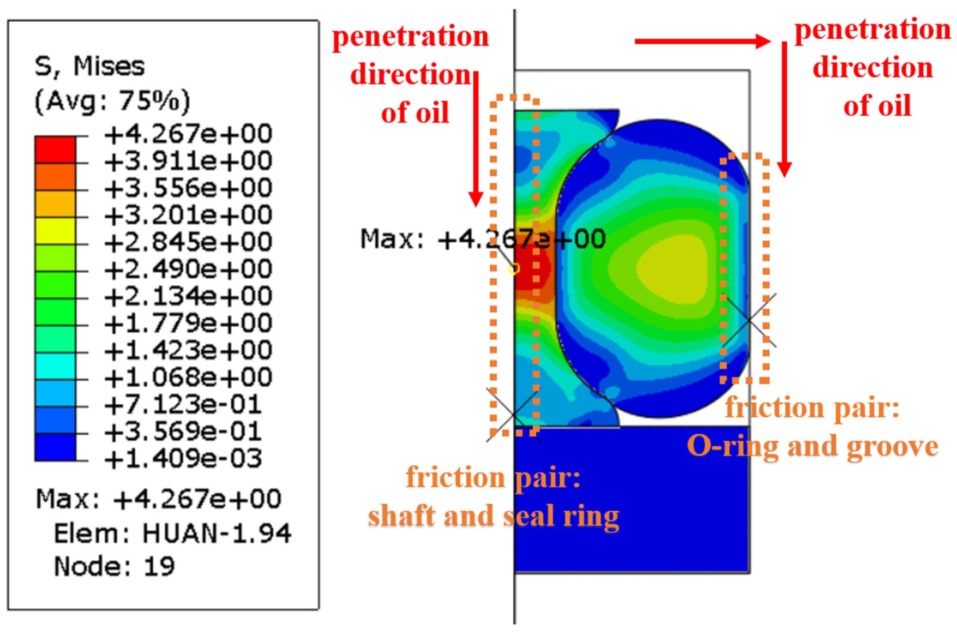
- The passage of aviation hydraulic fluid into the sealing system was simulated by pressure penetration. The pressure penetration method is shown in Figure 5. The load had to be increased gradually and the pressure was limited to the maximum value for all of the process. This was to avoid non-convergence in the step of loading.
3. Results and Discussion
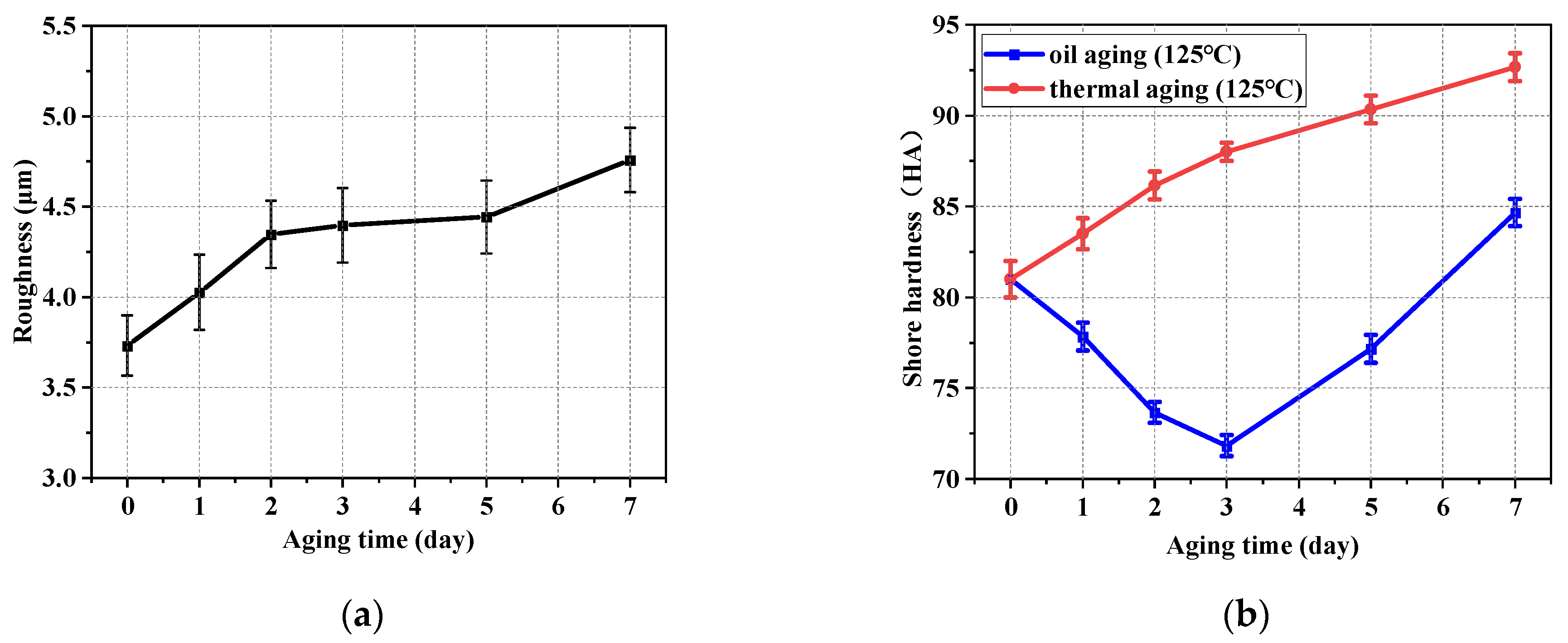
3.1. Effect of Aging on Mechanical Performance
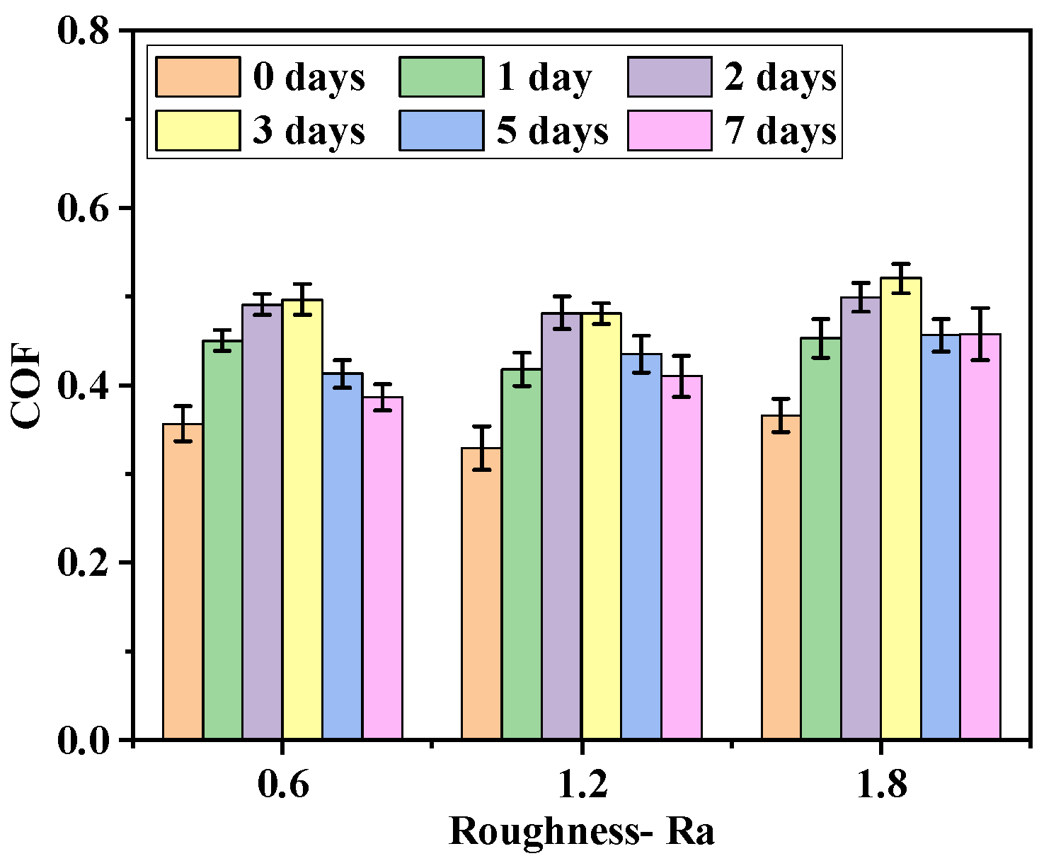
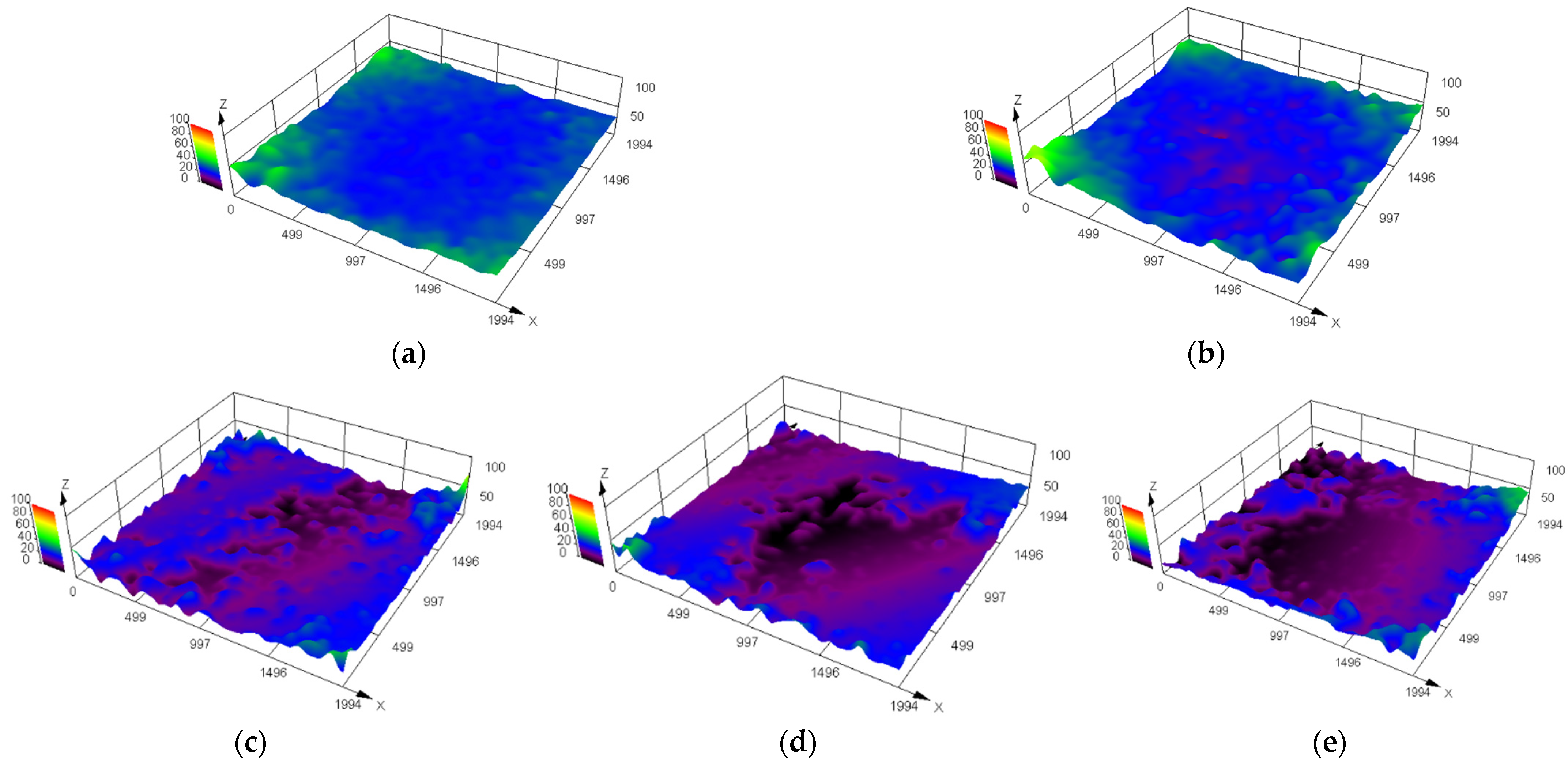
3.2. Effect of Aging on Tribological Behavior
3.3. Effect of Aging on Sealing Characteristics
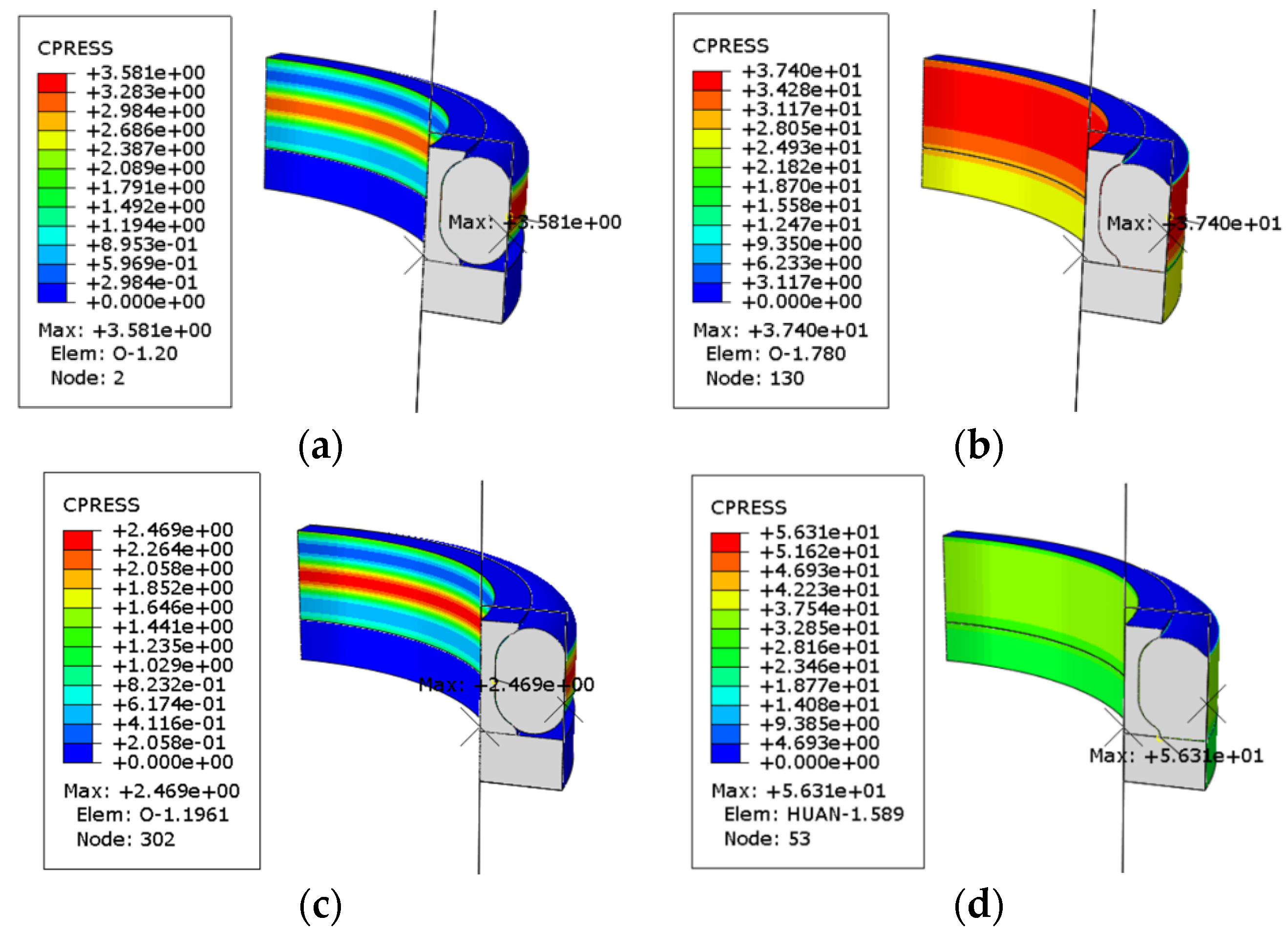
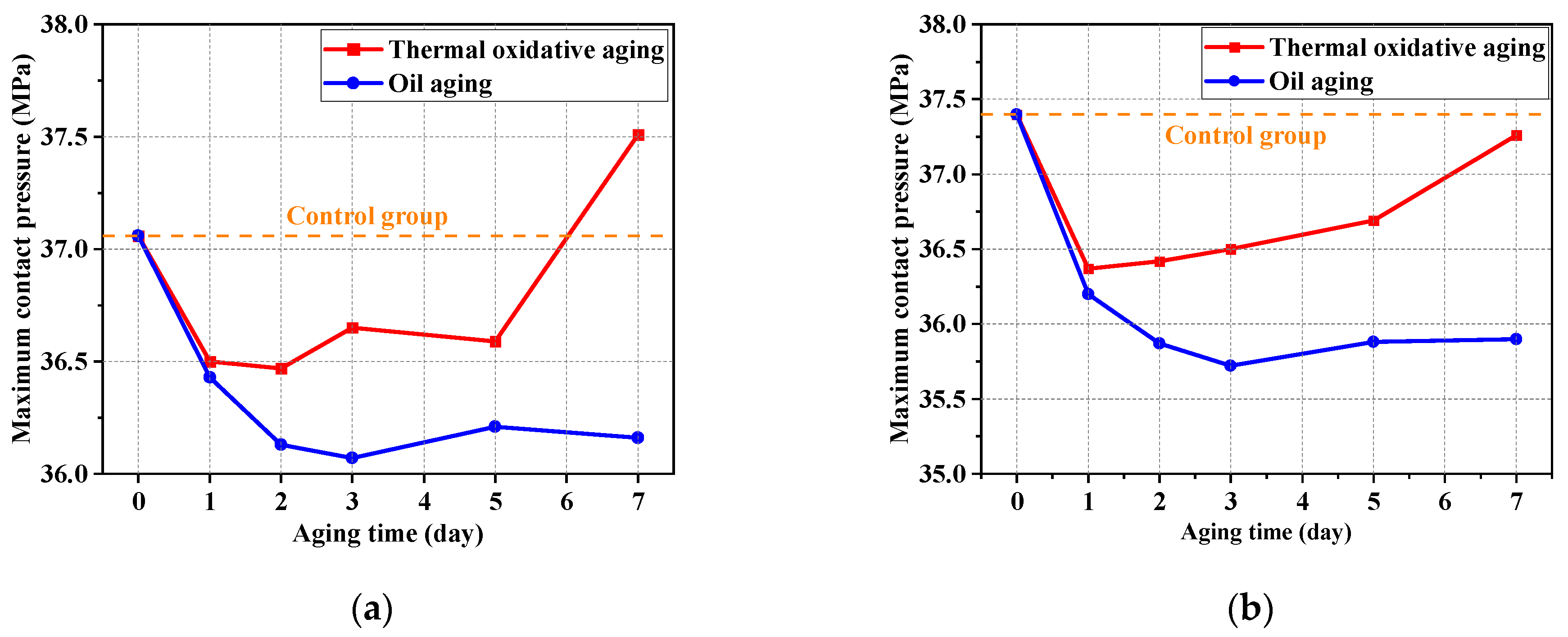
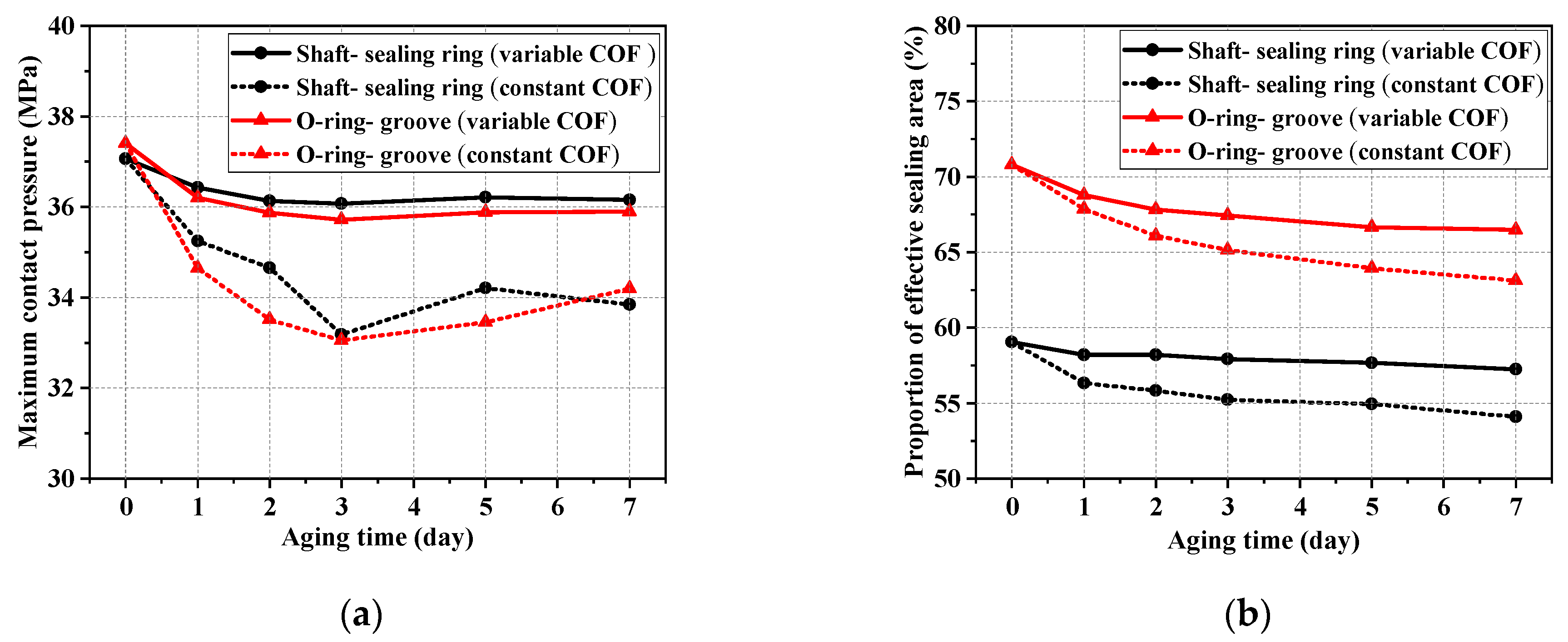
3.3.1. Contact Pressure
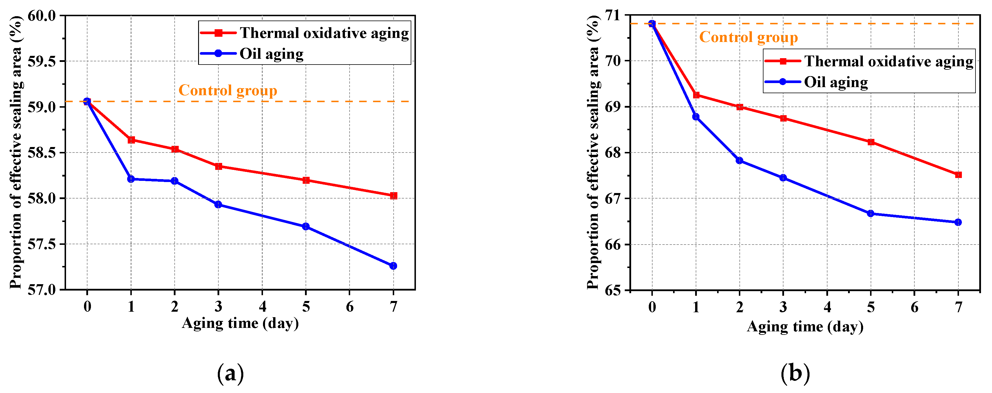
3.3.2. Proportion of Effective Sealing Area
4. Conclusions
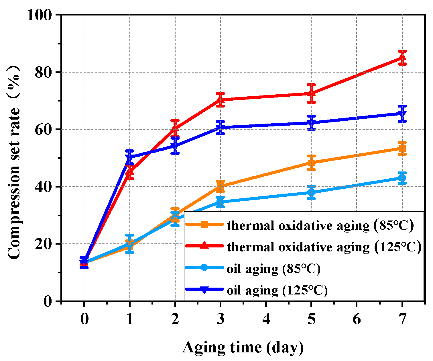
- (1)
- The elastic modulus increased with the increase in aging time in thermal oxidative aging. The elastic modulus for 7 days of thermal oxidative aging increased by 135.45% compared to the unaged value, and the elastic modulus for 7 days of oil aging increased by 15.03% compared to the unaged value. The compression set rate of NBR increased significantly with the increase in aging time and aging temperature. It was difficult for NBR to regain its original elasticity under a high ambient temperature.
- (2)
- Oil aging gradually changed the working surface condition of NBR and resulted in a rougher working surface. The COF between sealing friction pairs increased in the first 3 aging days and then decreased in other aging days. Moreover, after a certain number of friction cycles, the COF was significantly lower than that of the initial state.
- (3)
- The maximum contact pressure decreased by 2.43% between the shaft and sealing ring and decreased by 4.01% between the O-ring and groove. The proportion of effective sealing area decreased by 3.05% between the shaft and sealing ring and decreased by 6.11% between the O-ring and groove. Oil aging decreased the maximum contact pressure and proportion of effective sealing area compared to the unaged case. The sealing characteristics of NBR seals worsened with the increase in aging time. In addition, the proportion of effective sealing area between the O-ring and groove structure in general were greater than that between the shaft and seal ring. It showed better sealing characteristics between the O-ring and groove.
Author Contributions
Funding
Institutional Review Board Statement
Data Availability Statement
Conflicts of Interest
References
- Mayasari, H.E.; Sholeh, M.; Kinasih, N.A.; Sya’bani, M.W.; Pidhatika, B. The preparation of NBR/ENR composite for oil seal applications. Eur. J. Mater. Sci. Eng. 2020, 5, 161–170. [Google Scholar] [CrossRef]
- Pinedo, B.; Hadfield, M.; Tzanakis, I.; Conte, M.; Anand, M. Thermal analysis and tribological investigation on TPU and NBR elastomers applied to sealing applications. Tribol. Int. 2018, 127, 24–36. [Google Scholar] [CrossRef]
- Castagnet, S.; Ono, H.; Benoit, G.; Fujiwara, H.; Nishimura, S. Swelling measurement during sorption and decompression in a NBR exposed to high-pressure hydrogen. Int. J. Hydrog. Energy 2017, 42, 19359–19366. [Google Scholar] [CrossRef]
- Choi, S.S.; Ha, S.H. Influence of the swelling temperature and acrylonitrile content of NBR on the water swelling behaviors of silica-filled NBR vulcanizates. J. Ind. Eng. Chem. 2009, 15, 167–170. [Google Scholar] [CrossRef]
- Vishvanathperumal, S.; Anand, G. Effect of nanoclay/nanosilica on the mechanical properties, abrasion and swelling resistance of EPDM/SBR composites. Silicon 2020, 12, 1925–1941. [Google Scholar] [CrossRef]
- Liu, B.; He, S.; Meng, L.; Fu, X.; Gong, L.; Wang, H. Sealing mechanisms in volcanic faulted reservoirs in Xujiaweizi extension, northern Songliao Basin, northeastern China. AAPG Bull. 2021, 105, 1721–1743. [Google Scholar] [CrossRef]
- Sang, Y.; Wang, X.; Sun, W.; Liu, P. Numerical and experimental study on the friction of O ring for hydraulic seals. Aust. J. Mech. Eng. 2021, 19, 328–340. [Google Scholar] [CrossRef]
- Lu, L.; Luo, K.; Yang, W.; Zhang, S.; Wang, W.; Xu, H.; Wu, S. Insight into the anti-aging mechanisms of natural phenolic antioxidants in natural rubber composites using a screening strategy based on molecular simulation. RSC Adv. 2020, 10, 21318–21327. [Google Scholar] [CrossRef] [PubMed]
- Han, R.; Li, Y.; Zhu, Q.; Niu, K. Research on the preparation and thermal stability of silicone rubber composites: A review. Compos. Part C: Open Access 2022, 8, 100249. [Google Scholar] [CrossRef]
- Zhou, T.; Zhou, J.; Li, Q.; Li, B. Aging properties and mechanism of microwave-activated crumb rubber modified asphalt binder. Front. Mater. 2020, 7, 603938. [Google Scholar] [CrossRef]
- Losanno, D.; Palumbo, F.; Calabrese, A.; Barrasso, T.; Vaiana, N. Preliminary investigation of aging effects on recycled rubber fiber reinforced bearings (RR-FRBs). J. Earthq. Eng. 2022, 26, 5407–5424. [Google Scholar] [CrossRef]
- Abdullah, N.A.S.; Abdullah, F.F.; Sufian, A.H.; Abidin, A.N.S.Z.A.; Jamaludin, A.S.; Razali, M.N.M. Effect of degradation by temperature onto nitrile rubber elastomer mechanical properties. Mater. Today Proc. 2022, 48, 1941–1946. [Google Scholar] [CrossRef]
- Mehmood, B.; Akbar, M.; Ullah, R. Accelerated aging effect on high temperature vulcanized silicone rubber composites under DC voltage with controlled environmental conditions. Eng. Fail. Anal. 2020, 118, 104870. [Google Scholar] [CrossRef]
- Mostafa, A.; Abouel-Kasem, A.; Bayoumi, M.R.; El–Sebaie, M.G. The influence of CB loading on thermal aging resistance of SBR and NBR rubber compounds under different aging temperature. Mater. Des. 2009, 30, 791–795. [Google Scholar] [CrossRef]
- Mostafa, A.; Abouel-Kasem, A.; Bayoumi, M.R.; El–Sebaie, M.G. Insight into the effect of CB loading on tension, compression, hardness and abrasion properties of SBR and NBR filled compounds. Mater. Des. 2009, 30, 1785–1791. [Google Scholar] [CrossRef]
- Lee, Y.S.; Ha, K.R. Effects of acrylonitrile content on thermal characteristics and thermal aging properties of carbon black-filled NBR composite. J. Elastomers Plast. 2021, 53, 402–416. [Google Scholar] [CrossRef]
- Akulichev, A.G.; Alcock, B.; Echtermeyer, A.T. Elastic recovery after compression in HNBR at low and moderate temperatures: Experiment and modelling. Polym. Test. 2017, 61, 46–56. [Google Scholar] [CrossRef]
- Wang, X.; Xu, C.; Shen, Q.; Lin, M.; Zheng, Z.; Lin, B.; Fu, L. Conductivity controllable rubber films: Response to humidity based on a bio-based continuous segregated cell network. J. Mater. Chem. A 2021, 9, 8749–8760. [Google Scholar] [CrossRef]
- Gkouti, E.; Chaudhry, M.S.; Yenigun, B.; Czekanski, A. High-Strain-Rate Compression of Elastomers Subjected to Temperature and Humidity Conditions. Materials 2022, 15, 7931. [Google Scholar] [CrossRef]
- El Marzak, M.; Aicha, M.B.; Lamrani, B.; Alaoui, A.H. Analysis of the heat transfer time in rubber aggregate concrete as a function of humidity percentage at very high temperature. Mater. Today Proc. 2022, 57, 786–792. [Google Scholar]
- Jamal, M.; Martinez-Arguelles, G.; Giustozzi, F. Effect of waste tyre rubber size on physical, rheological and UV resistance of high-content rubber-modified bitumen. Constr. Build. Mater. 2021, 304, 124638. [Google Scholar] [CrossRef]
- Qian, G.; Yang, C.; Huang, H.; Gong, X.; Yu, H. Resistance to ultraviolet aging of nano-SiO2 and rubber powder compound modified asphalt. Materials 2020, 13, 5067. [Google Scholar] [CrossRef] [PubMed]
- Ramakanth, D.; Akhila, K.; Gaikwad, K.K.; Maji, P.K. UV-activated oxygen scavenging system based on natural rubber latex from Hevea brasiliensis for active packaging applications. Ind. Crops Prod. 2022, 178, 114658. [Google Scholar] [CrossRef]
- Fazli, A.; Rodrigue, D. Recycling waste tires into ground tire rubber (GTR)/rubber compounds: A review. J. Compos. Sci. 2020, 4, 103. [Google Scholar] [CrossRef]
- Andersson, J.; Gubanski, S.M.; Hillborg, H. Properties of interfaces in silicone rubber. IEEE Trans. Dielectr. Electr. Insul. 2007, 14, 137–145. [Google Scholar] [CrossRef]
- Petersson, L.; Meier, P.; Kornmann, X.; Hillborg, H. Effect of surface cleanliness of aluminium substrates on silicone rubber adhesion. J. Phys. D: Appl. Phys. 2010, 44, 034011. [Google Scholar] [CrossRef]
- Etsion, I.; Halperin, G. A laser surface textured hydrostatic mechanical seal. Tribol. Trans. 2002, 45, 430–434. [Google Scholar] [CrossRef]
- Wang, Q.; Hu, Y.P.; Ji, H.H. An anisotropic porous media model for leakage analysis of finger seal. Proc. Inst. Mech. Eng. Part G: J. Aerosp. Eng. 2020, 234, 280–292. [Google Scholar] [CrossRef]
- Ni, X.; Ma, C.; Sun, J.; Zhang, Y.; Yu, Q. A leakage model of contact mechanical seals based on the fractal theory of porous medium. Coatings 2020, 11, 20. [Google Scholar] [CrossRef]
- Rengasamy, S.; Eimer, B.C. Nanoparticle penetration through filter media and leakage through face seal interface of N95 filtering facepiece respirators. Ann. Occup. Hyg. 2012, 56, 568–580. [Google Scholar] [PubMed]
- Fischer, F.J.; Schmitz, K.; Tiwari, A.; Persson, B.N.J. Fluid leakage in metallic seals. Tribol. Lett. 2020, 68, 125. [Google Scholar] [CrossRef]
- Jiao, A.Y.; Quan, H.J.; Li, Z.Z.; Chen, Y. Study of magnetic abrasive finishing in seal ring groove surface operations. Int. J. Adv. Manuf. Technol. 2016, 85, 1195–1205. [Google Scholar] [CrossRef]
- Zhang, F.Y.; Chen, J.L.; Li, T.T.; Zhang, Y.F. Study and optimization of structural parameters of oil seal by response surface method. Int. J. Precis. Eng. Manuf. 2019, 20, 255–265. [Google Scholar] [CrossRef]
- Gu, Z.; Dai, Q.; Huang, W.; Wang, X. Effect of surface topography and roughness on the leakage of static seals. Surf. Topogr. Metrol. Prop. 2024, 12, 025014. [Google Scholar] [CrossRef]
- Aksit, M.F.; Chupp, R.E.; Dinc, O.S.; Demiroglu, M. Advanced seals for industrial turbine applications: Design approach and static seal development. J. Propuls. Power 2002, 18, 1254–1259. [Google Scholar] [CrossRef]
- Dinc, S.; Demiroglu, M.; Turnquist, N.; Mortzheim, J.; Goetze, G.; Maupin, J.; Hopkins, J.; Wolfe, C.; Florin, M. Fundamental design issues of brush seals for industrial applications. J. Turbomach. 2002, 124, 293–300. [Google Scholar] [CrossRef]
- Parmar, S.; Ramani, V.; Upadhyay, R.V.; Parekh, K. Design and development of large radial clearance static and dynamic magnetic fluid seal. Vacuum 2018, 156, 325–333. [Google Scholar] [CrossRef]
- Avanzini, A. Mechanical characterization and modeling of polymeric materials for high-pressure sealing. Exp. Mech. 2005, 45, 53–64. [Google Scholar] [CrossRef]
- Li, Y.; Shimizu, H. Novel morphologies of poly (phenylene oxide) (PPO)/polyamide 6 (PA6) blend nanocomposites. Polymer 2004, 45, 7381–7388. [Google Scholar] [CrossRef]
- Lan, B.; Li, P.; Luo, X.; Luo, H.; Yang, Q.; Gong, P. Hydrogen bonding and topological network effects on optimizing thermoplastic polyurethane/organic montmorillonite nanocomposite foam. Polymer 2021, 212, 123159. [Google Scholar] [CrossRef]
- Baena, J.C.; Wu, J.; Peng, Z. Wear performance of UHMWPE and reinforced UHMWPE composites in arthroplasty applications: A review. Lubricants 2015, 3, 413–436. [Google Scholar] [CrossRef]
- Saf, O.; Erol, H.; Kutlu, A.E. A method for material characterization of sealing system elastomers using sound transmission loss measurements. Polym. Test. 2022, 111, 107618. [Google Scholar] [CrossRef]
- Okada, H.; Itoh, T.; Suga, T. Wafer level sealing characterization method using Si micro cantilevers. Sens. Actuators A Phys. 2008, 147, 359–364. [Google Scholar] [CrossRef]
- GJB 250 A–96; Commission for Science, Technology and Industry for National Defence of China, Specification for Nitrile Rubber, Fuel and Hydraulic Fluid Resistant. Chinese Code Press: Beijing, China, 1996. (In Chinese)
- GB/T 3512–2014; Petroleum and Chemical Industry Association of China, Rubber, Vulcanized or Thermoplastic–Accelerated Ageing and Heat Resistance Tests–Air–Oven Method. Chinese Code Press: Beijing, China, 2014. (In Chinese)
- GB/T 1690–2010; Petroleum and Chemical Industry Association of China, Rubber, Vulcanized or Thermoplastic–Determination of the Effect of Liquids. Chinese Code Press: Beijing, China, 2010. (In Chinese)
- GB/T 7759.1–2015; Petroleum and Chemical Industry Association of China, Rubber, Vulcanized or Thermoplastic–Determination of Compression Set–Part 1: At Ambient or Elevated Temperatures. Chinese Code Press: Beijing, China, 2015. (In Chinese)
- GB/T 531.1–2008; Petroleum and Chemical Industry Association of China, Rubber, Vulcanized or Thermoplastic–Determination of Indentation Hardness–Part 1: Duromerer Method (Shore Hardness). Chinese Code Press: Beijing, China, 2008. (In Chinese)
- GB/T 7757–2009; Petroleum and Chemical Industry Association of China, Rubber, Vulcanized or Thermoplastic–Determination of Compression Stress–Strain Properties. Chinese Code Press: Beijing, China, 2009. (In Chinese)
- Kim, B.; Lee, S.B.; Lee, J.; Cho, S.; Park, H.; Yeom, S.; Park, S.H. A comparison among Neo-Hookean model, Mooney–Rivlin model, and Ogden model for chloroprene rubber. Int. J. Precis. Eng. Manuf. 2012, 13, 759–764. [Google Scholar] [CrossRef]
- Du, X.B.; Zhao, Y.Q.; Lin, F.; Xiao, Z. Parameters determination of Mooney–Rivlin model for rubber material of mechanical elastic wheel. Appl. Mech. Mater. 2017, 872, 198–203. [Google Scholar] [CrossRef]
- Karimi, A.; Navidbakhsh, M.; Shojaei, A.; Hassani, K.; Faghihi, S. Study of plaque vulnerability in coronary artery using Mooney–Rivlin model: A combination of finite element and experimental method. Biomed. Eng. Appl. Basis Commun. 2014, 26, 1450013. [Google Scholar] [CrossRef]
- Dai, H.H. Model equations for nonlinear dispersive waves in a compressible Mooney–Rivlin rod. Acta Mech. 1998, 127, 193–207. [Google Scholar] [CrossRef]


| 0 Days | 1 Day | 2 Days | 3 Days | 5 Days | 7 Days | |
|---|---|---|---|---|---|---|
| C10 | 1.0567 | −0.8381 | −1.2246 | −1.6025 | −3.0367 | −2.5138 |
| C01 | 0.1658 | 1.5967 | 2.0287 | 2.4740 | 3.8295 | 3.8574 |
| 0 Days | 1 Day | 2 Days | 3 Days | 5 Days | 7 Days | |
|---|---|---|---|---|---|---|
| C10 | 1.0567 | −0.6055 | −2.0126 | −2.1378 | −1.7491 | −1.4055 |
| C01 | 0.1658 | 1.4429 | 2.5909 | 2.6745 | 2.3664 | 2.0035 |
Disclaimer/Publisher’s Note: The statements, opinions and data contained in all publications are solely those of the individual author(s) and contributor(s) and not of MDPI and/or the editor(s). MDPI and/or the editor(s) disclaim responsibility for any injury to people or property resulting from any ideas, methods, instructions or products referred to in the content. |
© 2024 by the authors. Licensee MDPI, Basel, Switzerland. This article is an open access article distributed under the terms and conditions of the Creative Commons Attribution (CC BY) license (https://creativecommons.org/licenses/by/4.0/).
Share and Cite
Li, Y.; Wu, J.; Chen, Z.; Zhang, Z.; Su, B.; Wang, Y. The Influence of Oil and Thermal Aging on the Sealing Characteristics of NBR Seals. Polymers 2024, 16, 2501. https://doi.org/10.3390/polym16172501
Li Y, Wu J, Chen Z, Zhang Z, Su B, Wang Y. The Influence of Oil and Thermal Aging on the Sealing Characteristics of NBR Seals. Polymers. 2024; 16(17):2501. https://doi.org/10.3390/polym16172501
Chicago/Turabian StyleLi, Yiding, Jian Wu, Zhihao Chen, Ziqi Zhang, Benlong Su, and Youshan Wang. 2024. "The Influence of Oil and Thermal Aging on the Sealing Characteristics of NBR Seals" Polymers 16, no. 17: 2501. https://doi.org/10.3390/polym16172501