
Evaluation of Bond Strength of Concrete Repaired Using Polyurethane Grout Material under Static and Impact Loads Coupled with Statistical Analysis


Abstract
:1. Introduction
2. Materials and Methods
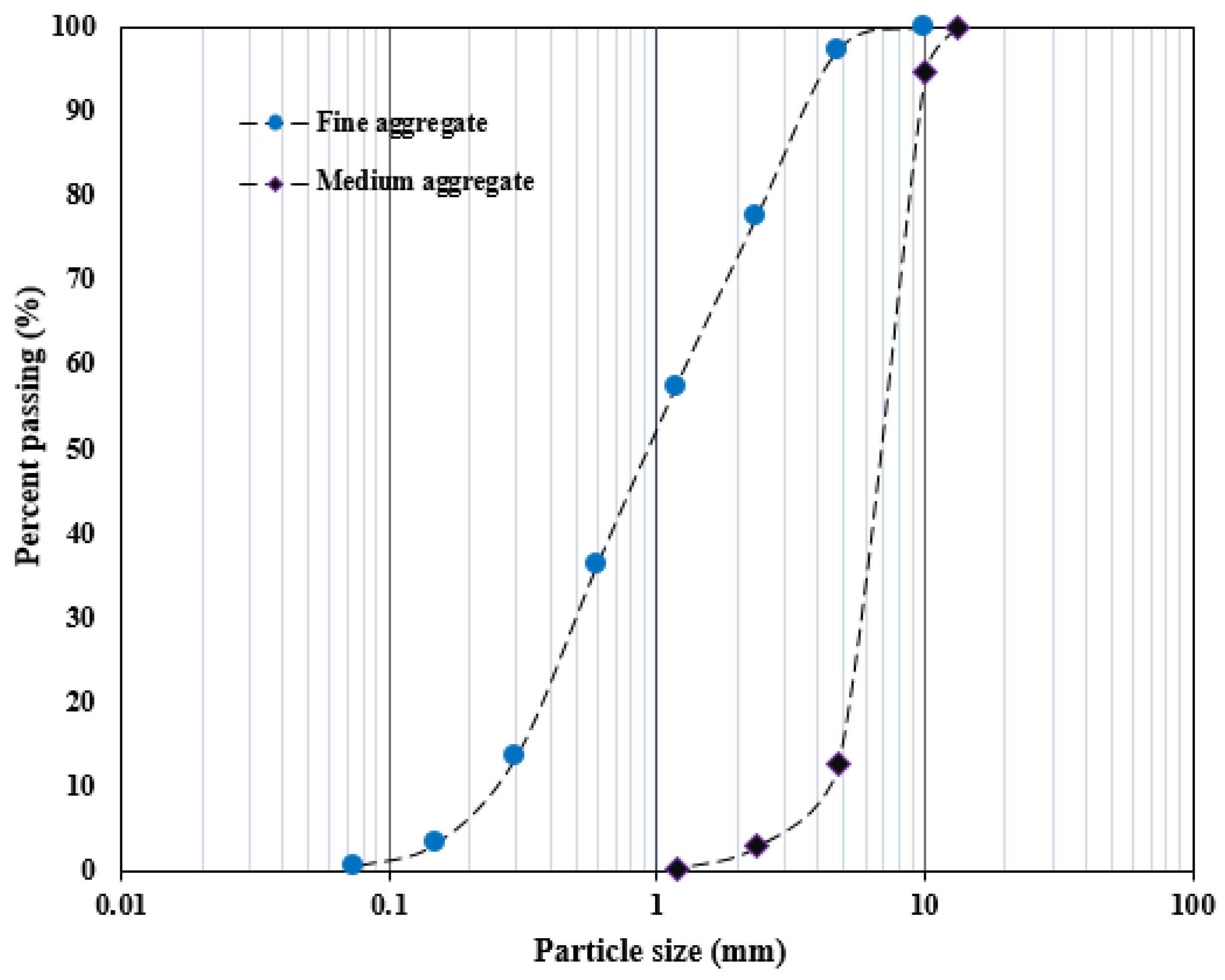
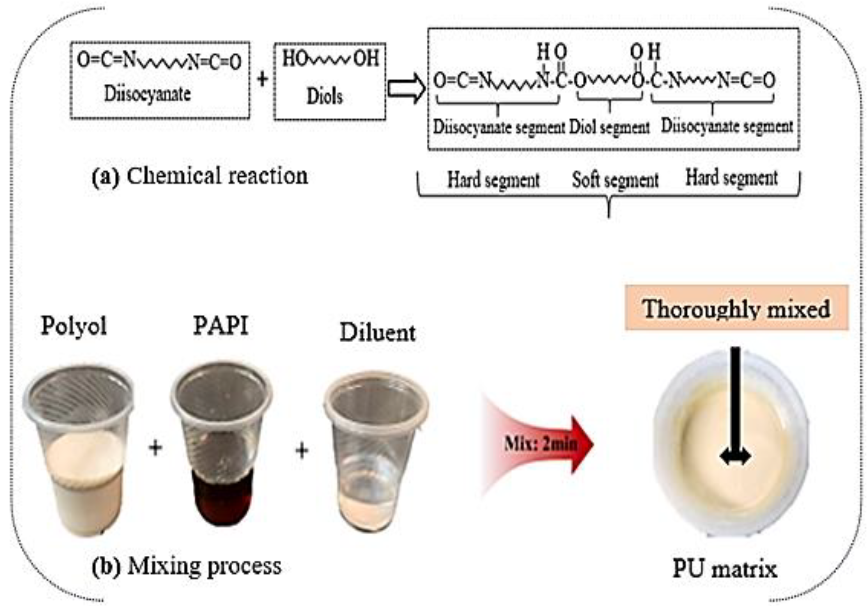
2.1. Materials
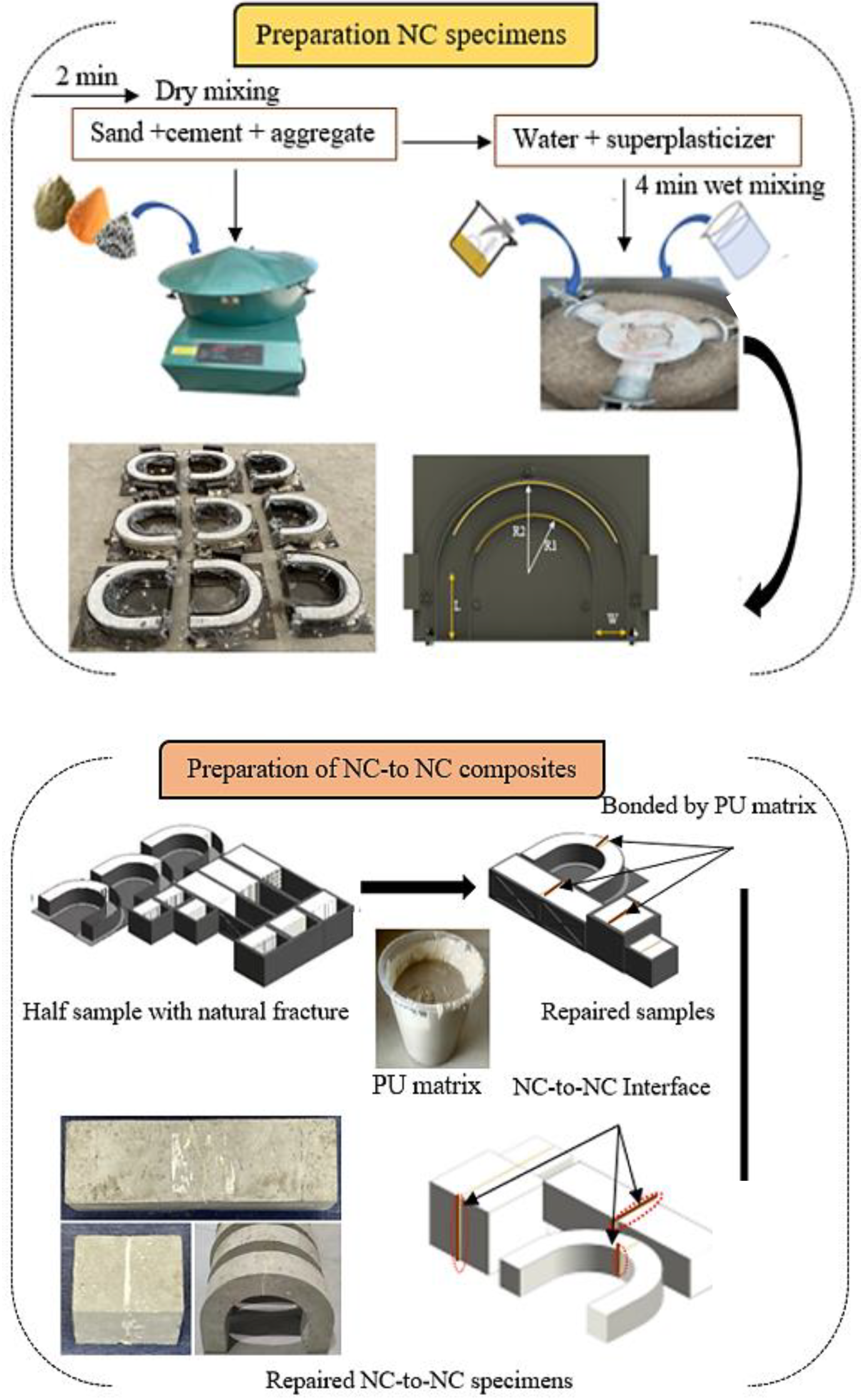
Sample Preparation
2.2. Testing Methods
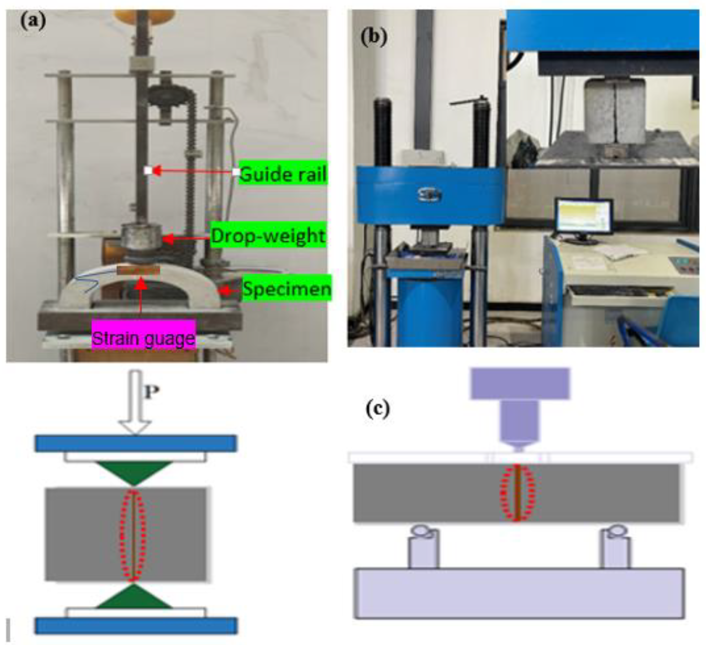
2.2.1. Impact Strength Test
2.2.2. Compression and Bond Strength Test
3. Results and Discussion
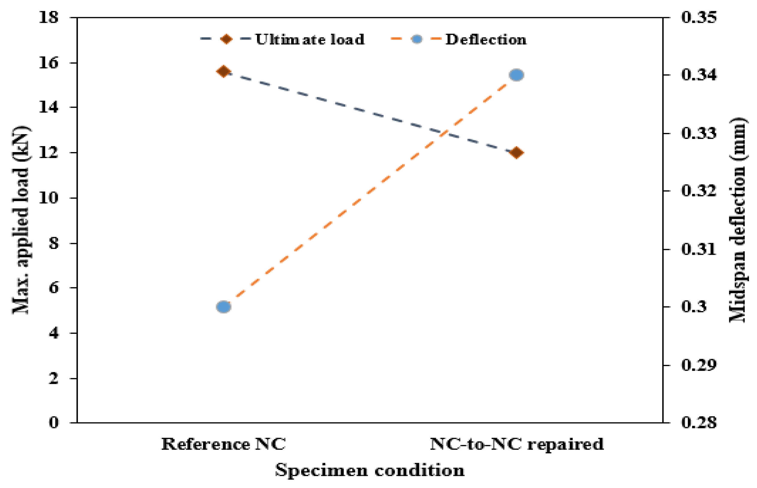
3.1. Flexural and Compression Properties of the Composite Specimen
3.2. Bond Properties of the NC-to-NC Repaired Specimen
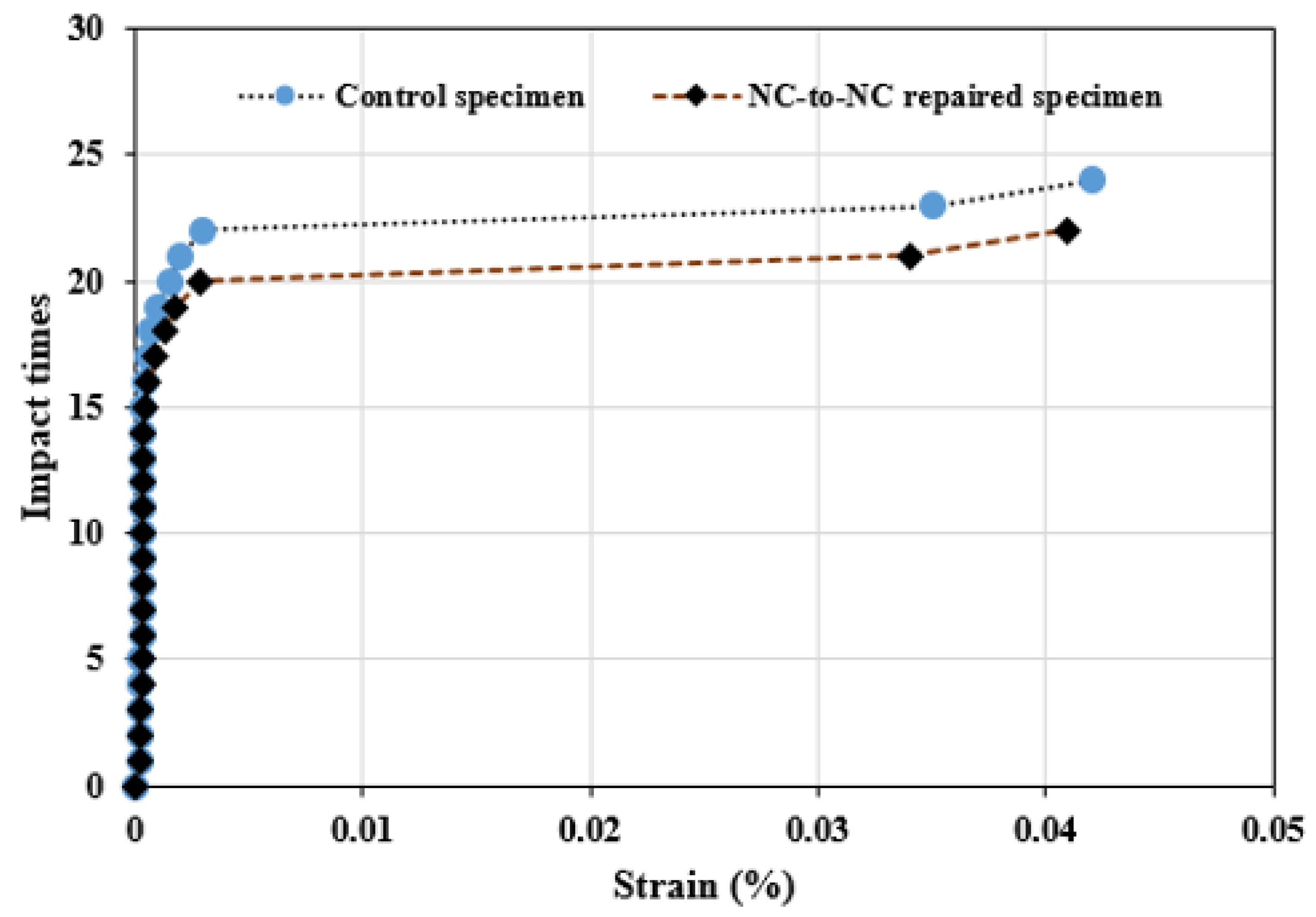
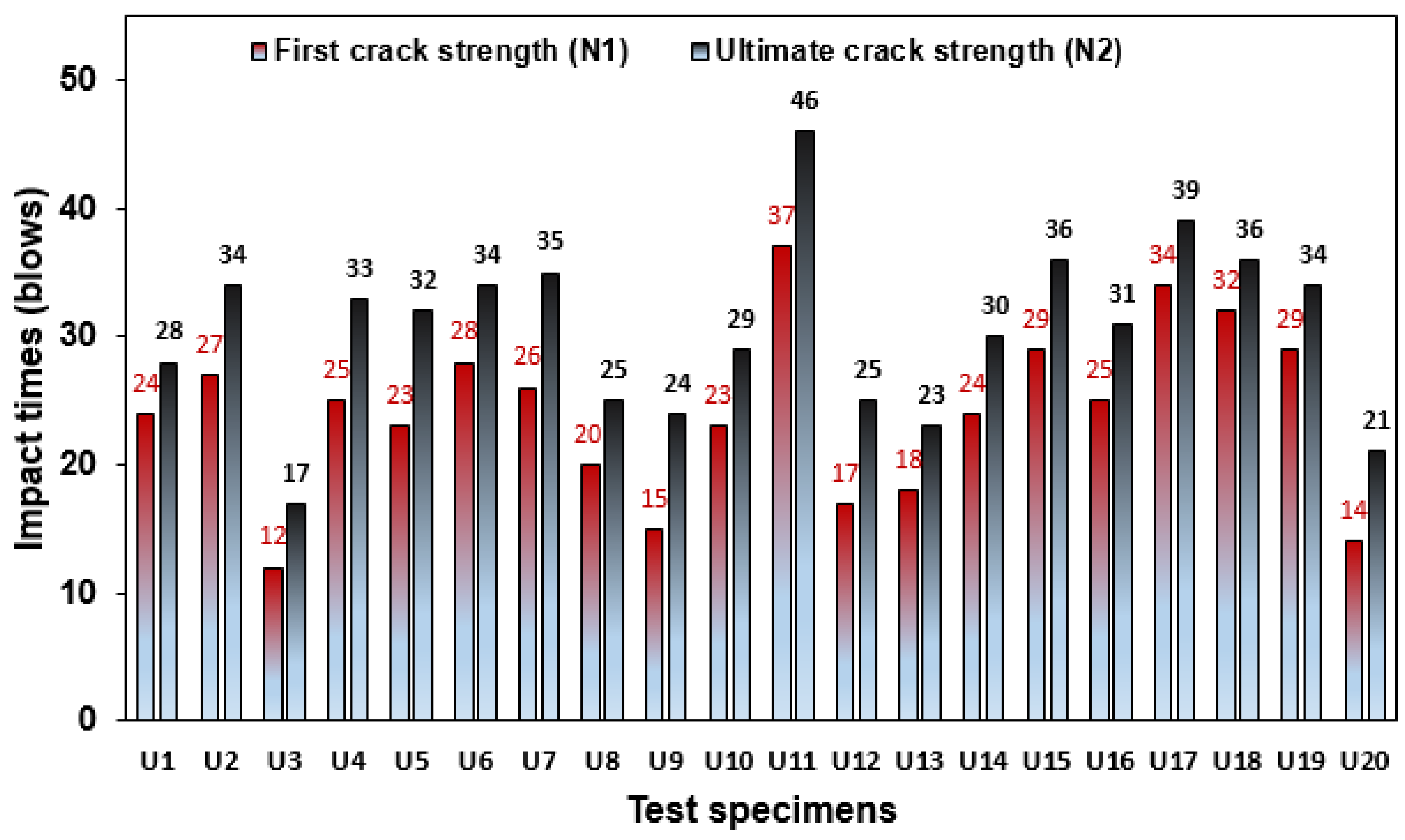
3.3. Impact Resistance of the Repaired U-Shaped Specimen
3.3.1. Impact Strength of NC-R Specimen
3.3.2. Impact Strength of NC-to-NC Repaired Specimen
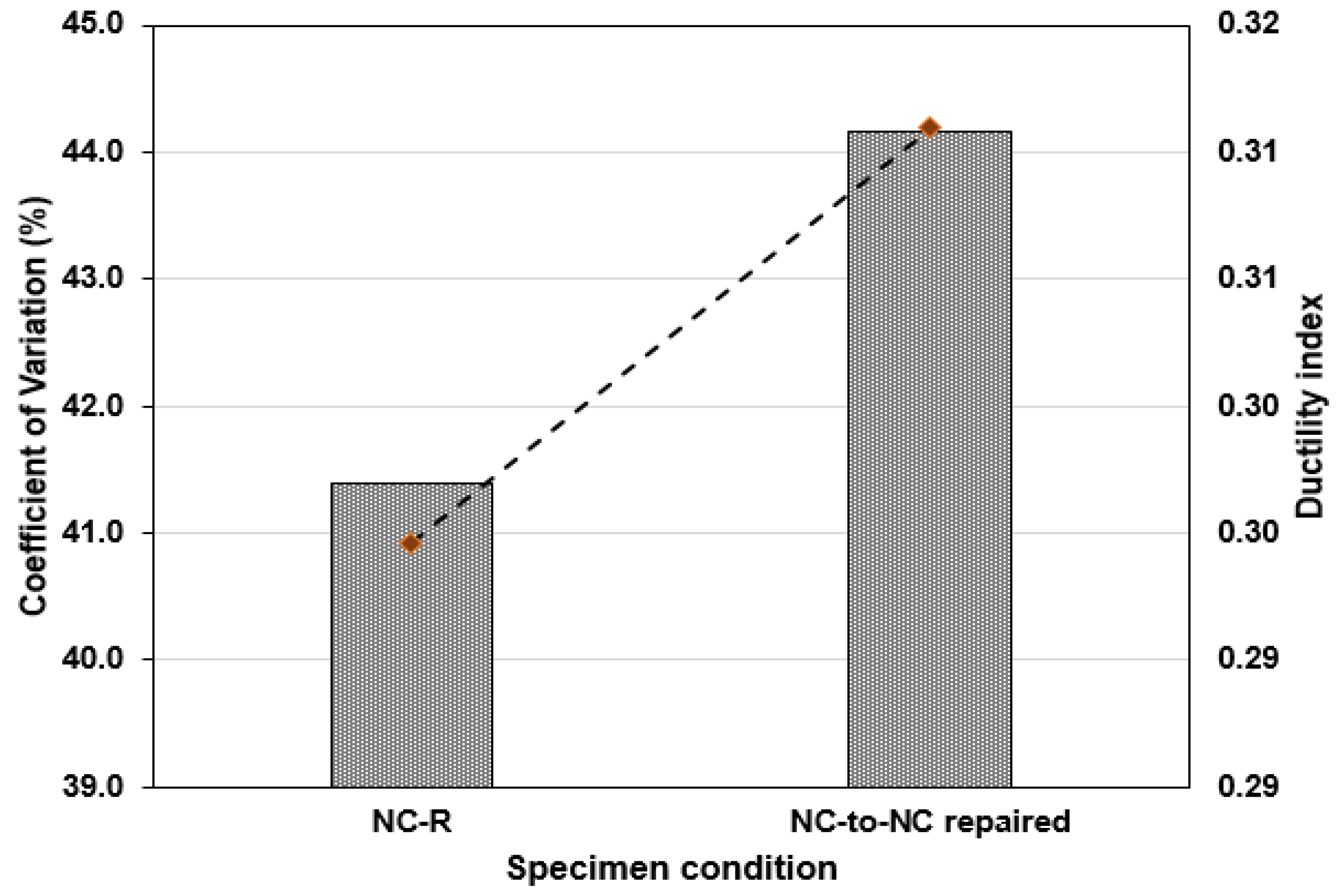
3.4. Coefficient of Variation (CoV) and Ductility Index (λ) of Test Specimens
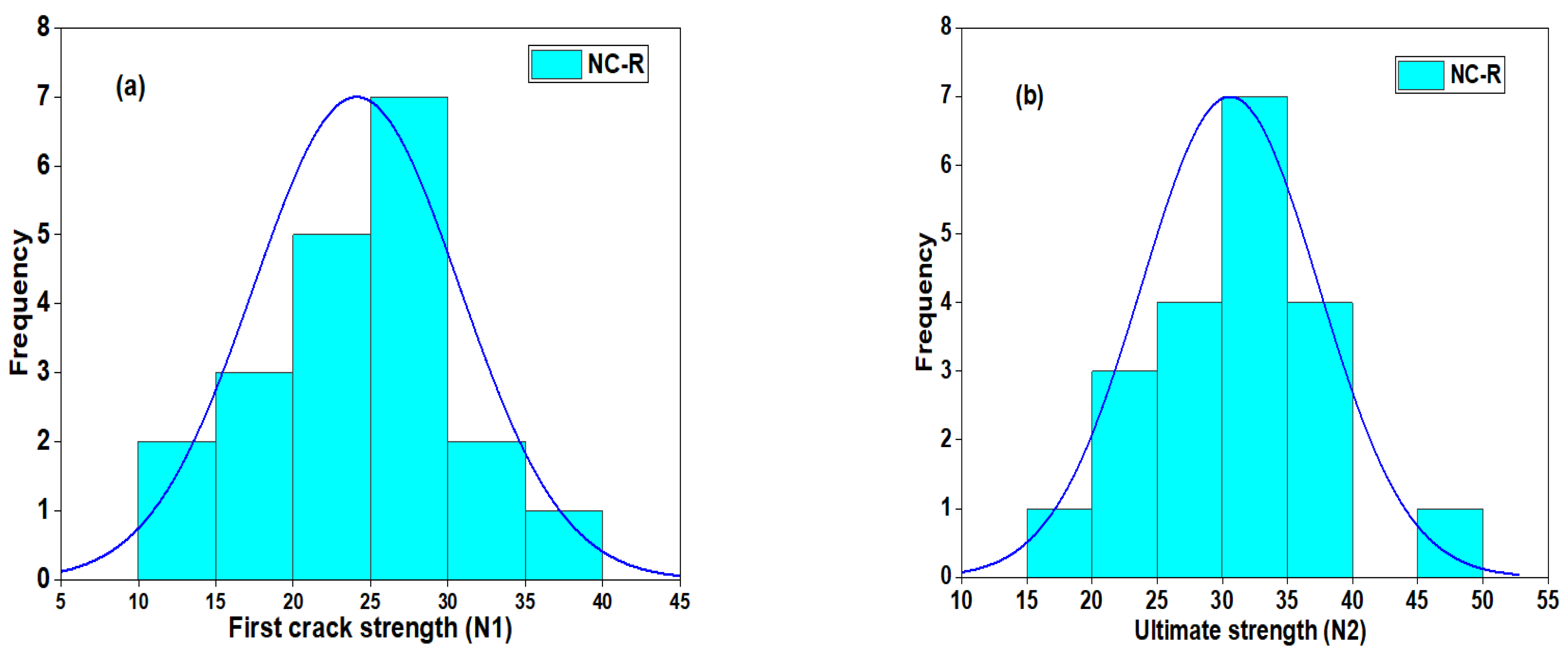
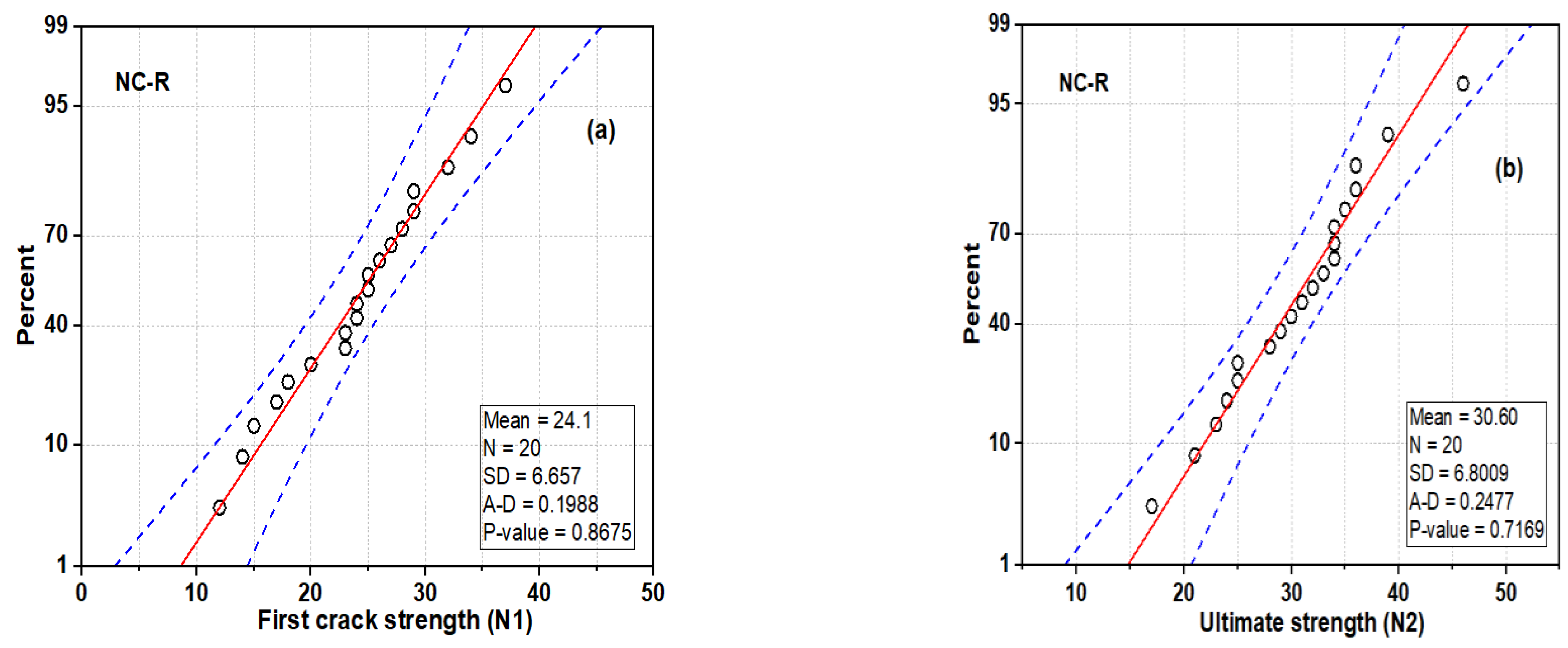
3.5. Statistical Analysis of Impact Strength Data
3.5.1. Normal and Probability Distribution of NC-R Specimen
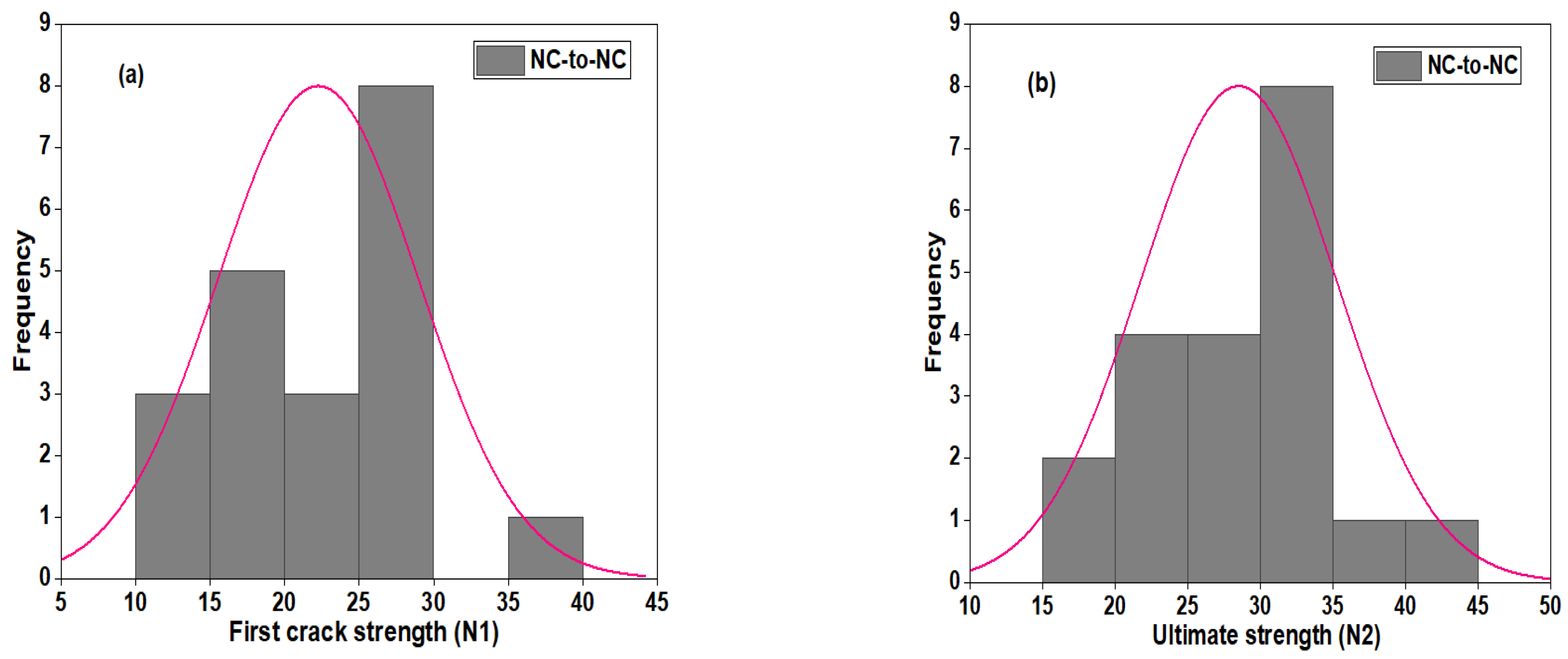
3.5.2. Normal and Probability Distribution of NC-to-NC Repaired Specimens
3.6. Failure Pattern of the Test Specimen
4. Conclusions
- Polyurethane binders effectively repair materials that provide adequate bond strength between the NC substrates, which exceeds the minimum allowable bond strength specified by the ASTM ACI 546-06 for rehabilitating impaired concrete structures.
- The flexural strength of the reference beam is slightly higher than that of the repaired beam specimen. However, the repaired specimen exhibits a more significant deflection than the NC-R samples. The compressive strength of the NC-to-NC repaired specimens loaded along and parallel to the interface plane revealed a decrease in compressive strength of 47.3% and 31.5% compared to the NC-R samples, respectively.
- The mean number of blows at the cracking stages appeared nearly equal for reference and repaired NC-to-NC specimens, indicating the effectiveness of the PU matrix in bonding the two pieces together with high strength under repeated impact loads.
- Common failure patterns were observed for all NC-to-NC repaired specimens, which were characterized by the separation of the two bonded components occurring at interface. However, the cube specimen tested perpendicular to the applied load exhibited the crushing and spalling of concrete at the upper section of the specimen.
Author Contributions
Funding
Data Availability Statement
Acknowledgments
Conflicts of Interest
References
- Assaad, J.J. Development and use of polymer-modified cement for adhesive and repair applications. Constr. Build. Mater. 2018, 168, 139–148. [Google Scholar] [CrossRef]
- Al-shawafi, A.; Zhu, H.; Haruna, S.I.; Bo, Z.; Laqsum, S.A.; Borito, S.M. Impact resistance of ultra-high-performance concrete retrofitted with polyurethane grout material: Experimental investigation and statistical analysis. Sructures 2023, 55, 185–200. [Google Scholar] [CrossRef]
- Alderete, N.M.; Zaccardi, Y.A.V.; De Belie, N. Mechanism of long-term capillary water uptake in cementitious materials. Cem. Concr. Compos. 2020, 106, 103448. [Google Scholar] [CrossRef]
- Zaccardi, Y.A.V.; Alderete, N.M.; De Belie, N. Improved model for capillary absorption in cementitious materials: Progress over the fourth root of time. Cem. Concr. Res. 2017, 100, 153–165. [Google Scholar] [CrossRef]
- Shao, J.; Zhu, H.; Zuo, X.; Lei, W.; Mirgan, S.; Liang, J.; Duan, F. Effect of waste rubber particles on the mechanical performance and deformation properties of epoxy concrete for repair. Constr. Build. Mater. 2020, 241, 118008. [Google Scholar] [CrossRef]
- Afzal, A.; Kausar, A.; Siddiq, M. Role of polymeric composite in civil engineering applications: A review. Polym. Technol. Mater. 2020, 59, 1023–1040. [Google Scholar] [CrossRef]
- Liu, G.; Otsuka, H.; Mizuta, Y.; Shimitsu, A. A foundational study on static mechanical characteristics of the super lightweight and high strength material using fly-ash. J.-Soc. Mater. Sci. Jpn. 2006, 55, 738. [Google Scholar] [CrossRef]
- Hussain, H.K.; Zhang, L.Z.; Liu, G.W. An experimental study on strengthening reinforced concrete T-beams using new material polyurethane-cement (PUC). Constr. Build. Mater. 2013, 40, 104–117. [Google Scholar] [CrossRef]
- Reis, J.M.L.; Ferreira, A.J.M. Assessment of fracture properties of epoxy polymer concrete reinforced with short carbon and glass fibers. Constr. Build. Mater. 2004, 18, 523–528. [Google Scholar] [CrossRef]
- Haruna, S.I.; Ibrahim, Y.E.; Han, Z.; Farouk, A.I.B. Flexural Response of Concrete Specimen Retrofitted with PU Grout Material: Experimental and Numerical Modeling. Polymers 2023, 15, 4114. [Google Scholar] [CrossRef]
- Jiang, W.; Zhu, H.; Haruna, S.I.; Shao, J.; Yu, Y.; Wu, K. Mechanical properties and freeze–thaw resistance of polyurethane-based polymer mortar with crumb rubber powder. Constr. Build. Mater. 2022, 352, 129040. [Google Scholar] [CrossRef]
- Liu, K.; Tong, J.; Huang, M.; Wang, F.; Pang, H. Model and experimental studies on the effects of load characteristics and polyurethane densities on fatigue damage of rigid polyurethane grouting materials. Constr. Build. Mater. 2022, 347, 128595. [Google Scholar] [CrossRef]
- Al-Atroush, M.E.; Shabbir, O.; Almeshari, B.; Waly, M.; Sebaey, T.A. A Novel Application of the Hydrophobic Polyurethane Foam: Expansive Soil Stabilization. Polymers 2021, 13, 1335. [Google Scholar] [CrossRef] [PubMed]
- Junaedi, H.; Khan, T.; Sebaey, T.A. Characteristics of Carbon-Fiber-Reinforced Polymer Face Sheet and Glass-Fiber-Reinforced Rigid Polyurethane Foam Sandwich Structures under Flexural and Compression Tests. Materials 2023, 16, 5101. [Google Scholar] [CrossRef] [PubMed]
- Farouk, A.I.B.; Jinsong, Z. Prediction of Interface Bond Strength Between Ultra-High-Performance Concrete (UHPC) and Normal Strength Concrete (NSC) Using a Machine Learning Approach. Aab. J. Sci. Eng. 2022, 47, 5337–5363. [Google Scholar] [CrossRef]
- Li, X.; Wang, M.; Zheng, D.; Fang, H.; Wang, F.; Wan, J. Study on the failure mechanism between polyurethane grouting material and concrete considering the effect of moisture by digital image correlation. J. Build. Eng. 2023, 67, 105948. [Google Scholar] [CrossRef]
- Bahraq, A.A.; Al-Osta, M.A.; Ahmad, S.; Al-Zahrani, M.M.; Al-Dulaijan, S.O.; Rahman, M.K. Experimental and Numerical Investigation of Shear Behavior of RC Beams Strengthened by Ultra-High Performance Concrete. Int. J. Concr. Struct. Mater. 2019, 13, 6. [Google Scholar] [CrossRef]
- Li, Z.; Rangaraju, P.R. Effect of surface roughness on the bond between ultrahigh-performance and precast concrete in bridge deck connections. Tansp. Res. Rec. 2016, 2577, 88–96. [Google Scholar] [CrossRef]
- Yang, Y.; Xu, C.; Yang, J.; Wang, K. Experimental study on flexural behavior of precast hybrid UHPC-NSC beams. J. Build. Eng. 2023, 70, 106354. [Google Scholar] [CrossRef]
- Kim, S.; Yi, J.-H.; Hong, H.; Choi, S.I.; Kim, D.; Kim, M.O. Interfacial Bond Properties of Underwater Concrete Coated with Bisphenol A Epoxy Resins. Polymers 2023, 15, 4290. [Google Scholar] [CrossRef] [PubMed]
- Sun, W.; Wang, S.; Liu, G.; Han, W.; Hou, Q.; Zhang, Z.; Xiu, Z. Enhancing concrete bond strength with silicate-based curing agents: A focus on surface damage repair. J. Build. Eng. 2024, 93, 109869. [Google Scholar] [CrossRef]
- Tan, J.; Dan, H.; Ma, Z. Metakaolin based geopolymer mortar as concrete repairs: Bond strength and degradation when subjected to aggressive environments. Ceram. Int. 2022, 48, 23559–23570. [Google Scholar] [CrossRef]
- Kim, K.; Le, T.H. Evaluation of the Polymer Modified Tack Coat on Aged Concrete Pavement: An Experimental Study on Adhesion Properties. Polymers 2023, 15, 2830. [Google Scholar] [CrossRef] [PubMed]
- Vishavkarma, A.; Harish, K.V. Tension and bond characteristics of foam concrete for repair applications. Cse Stud. Constr. Mater. 2024, 20, e02767. [Google Scholar]
- Rousakis, T.; Ilki, A.; Kwiecien, A.; Viskovic, A.; Gams, M.; Triller, P.; Ghiassi, B.; Benedetti, A.; Rakicevic, Z.; Colla, C.; et al. Deformable Polyurethane Joints and Fibre Grids for Resilient Seismic Performance of Reinforced Concrete Frames with Orthoblock Brick Infills. Polymers 2020, 12, 2869. [Google Scholar] [CrossRef]
- Al-shawafi, A.; Zhu, H.; Bo, Z.; Haruna, S.I.; Ibrahim, Y.E.; Farouk, A.I.B.; Laqsum, S.A.; Shao, J. Bond behavior between normal concrete and UHPC and PUC layers subjected to different loading conditions coupled with fracture analysis technique. J. Build. Eng. 2024, 86, 108880. [Google Scholar] [CrossRef]
- Zhang, B.; Yu, J.; Chen, W.; Liu, H.; Li, H. Multi-scale investigation on the interfacial behavior of between NC and UHPC in flexural members considering influence of the interface morphology. Compos. Struct. 2024, 345, 118388. [Google Scholar] [CrossRef]
- Lin, L.; Wu, Z.; Zhang, D.; Wu, X.; Liu, D.; Zhang, Y.; Wu, C.; Wang, H.; Wang, F.; Liu, Y.; et al. Shear failure analysis of UHPC-NC composites interface with U-shaped studs. Sructures 2024, 64, 106556. [Google Scholar] [CrossRef]
- EL Afandi, M.; Yehia, S.; Landolsi, T.; Qaddoumi, N.; Elchalakani, M. Concrete-to-concrete bond Strength: A review. Constr. Build. Mater. 2023, 363, 129820. [Google Scholar] [CrossRef]
- GB175-2007; Common Portland Cement. Chinese National Standard: Beijing, China, 2007.
- JGJ55-2011; Chinese National Standards for Cement Concrete Mixture Preparation. Chinese National Standard: Beijing, China, 2011.
- Haruna, S.I.; Zhu, H.; Shao, J. Experimental study, modeling, and reliability analysis of impact resistance of micro steel fiber-reinforced concrete modified with nano silica. Struct. Concr. 2022, 23, 1659–1674. [Google Scholar] [CrossRef]
- GB/T50081-2002; Standard for Test Method of Mechanical Properties on Ordinary Concrete. Chinese National Standard: Beijing, China, 2002.
- ASTM C496/C496M-04e1; Standard Test Method for Splitting Tensile Strength of Cylindrical Concrete Specimens. ASTM International: West Conshohocken, PA, USA, 2008.
- ASTM C78; Standard Test Method for Flexural Strength of Concrete. ASTM International: West Conshohocken, PA, USA, 2016.
- ACI 546-06; Concrete Repair Guide, ACI Committee. American Concrete Institute: Farmington Hills, MI, USA, 1996.
- ACI 544.2R-89; Measurement of Properties of Fiber Reinforced Concrete. American Concrete Institute: Farmington Hills, MI, USA, 1989; pp. 433–439.
- Nataraja, M.C.; Dhang, N.; Gupta, A.P. Statistical variations in impact resistance of steel fiber-reinforced concrete subjected to drop weight test. Cem. Concr. Res. 1999, 29, 989–995. [Google Scholar] [CrossRef]
- Badr, A.; Ashour, A.F.; Platten, A.K. Statistical variations in impact resistance of polypropylene fibre-reinforced concrete. Int. J. Impact Eng. 2006, 32, 1907–1920. [Google Scholar] [CrossRef]
- Mastali, M.; Dalvand, A. The impact resistance and mechanical properties of self-compacting concrete reinforced with recycled CFRP pieces. Compos. Part B Eng. 2016, 92, 360–376. [Google Scholar] [CrossRef]
- Cao, H. Experimental investigation on the static and impact behaviors of basalt fiber-reinforced concrete. Open Civ. Eng. J. 2017, 11, 14–21. [Google Scholar] [CrossRef]
- Rai, B.; Singh, N.K. Statistical and experimental study to evaluate the variability and reliability of impact strength of steel-polypropylene hybrid fiber reinforced concrete. J. Build. Eng. 2021, 44, 102937. [Google Scholar] [CrossRef]
- Prasad, N.; Murali, G. Exploring the impact performance of functionally-graded preplaced aggregate concrete incorporating steel and polypropylene fibres. J. Build. Eng. 2021, 35, 102077. [Google Scholar] [CrossRef]
- Abid, S.R.; Abdul-Hussein, M.L.; Ayoob, N.S.; Ali, S.H.; Kadhum, A.L. Repeated drop-weight impact tests on self-compacting concrete reinforced with micro-steel fiber. Hliyon 2020, 6, e03198. [Google Scholar] [CrossRef]
- Ding, Y.; Li, D.; Zhang, Y.; Azevedo, C. Experimental investigation on the composite effect of steel rebars and macro fibers on the impact behavior of high performance self-compacting concrete. Constr. Build. Mater. 2017, 136, 495–505. [Google Scholar] [CrossRef]
- Yap, S.P.; Bu, C.H.; Alengaram, U.J.; Mo, K.H.; Jumaat, M.Z. Flexural toughness characteristics of steel–polypropylene hybrid fibre-reinforced oil palm shell concrete. Mater. Des. 2014, 57, 652–659. [Google Scholar] [CrossRef]
- Haruna, S.I.; Zhu, H.; Jiang, W.; Shao, J. Evaluation of impact resistance properties of polyurethane-based polymer concrete for the repair of runway subjected to repeated drop-weight impact test. Constr. Build. Mater. 2021, 309, 125152. [Google Scholar] [CrossRef]


| Specimen ID | Cement | Sand | Medium Aggregate | Water |
|---|---|---|---|---|
| NC | 425 | 718 | 966 | 170 |
| Specimen ID | PU Resin | Diluent (kg/m3) | |
|---|---|---|---|
| Polyol (kg/m3) | PAPI (kg/m3) | ||
| PU matrix | 362 | 60 | 7.2 |
| S/N | NC-R | NC-to-NC Specimen | ACI min Acceptable Value |
|---|---|---|---|
| 1 | 6.2 | 2.5 | - |
| 2 | 6.7 | 2.9 | - |
| 3 | 6.0 | 3.0 | - |
| Average | 6.3 | 2.8 | 1.7–2.1 |
Disclaimer/Publisher’s Note: The statements, opinions and data contained in all publications are solely those of the individual author(s) and contributor(s) and not of MDPI and/or the editor(s). MDPI and/or the editor(s) disclaim responsibility for any injury to people or property resulting from any ideas, methods, instructions or products referred to in the content. |
© 2024 by the authors. Licensee MDPI, Basel, Switzerland. This article is an open access article distributed under the terms and conditions of the Creative Commons Attribution (CC BY) license (https://creativecommons.org/licenses/by/4.0/).
Share and Cite
Haruna, S.I.; Ibrahim, Y.E.; Al-shawafi, A. Evaluation of Bond Strength of Concrete Repaired Using Polyurethane Grout Material under Static and Impact Loads Coupled with Statistical Analysis. Polymers 2024, 16, 2729. https://doi.org/10.3390/polym16192729
Haruna SI, Ibrahim YE, Al-shawafi A. Evaluation of Bond Strength of Concrete Repaired Using Polyurethane Grout Material under Static and Impact Loads Coupled with Statistical Analysis. Polymers. 2024; 16(19):2729. https://doi.org/10.3390/polym16192729
Chicago/Turabian StyleHaruna, Sadi Ibrahim, Yasser E. Ibrahim, and Ali Al-shawafi. 2024. "Evaluation of Bond Strength of Concrete Repaired Using Polyurethane Grout Material under Static and Impact Loads Coupled with Statistical Analysis" Polymers 16, no. 19: 2729. https://doi.org/10.3390/polym16192729