Static and Impact Properties of Flax-Reinforced Polymers Prepared with Conventional Epoxy and Sustainable Resins


Abstract
:1. Introduction
2. Materials and Methods
2.1. Materials, Methods and Laminate Production
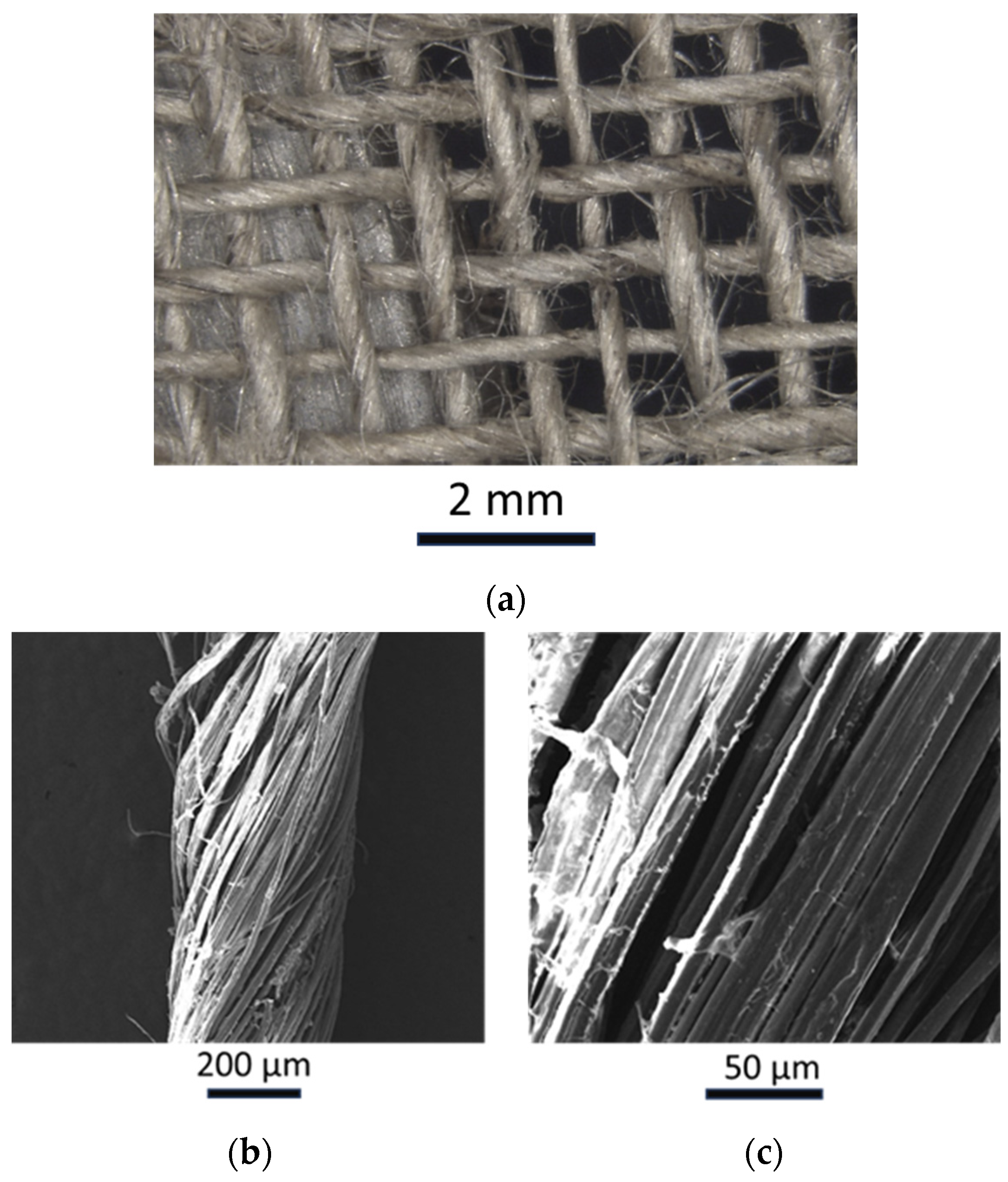
2.1.1. Materials
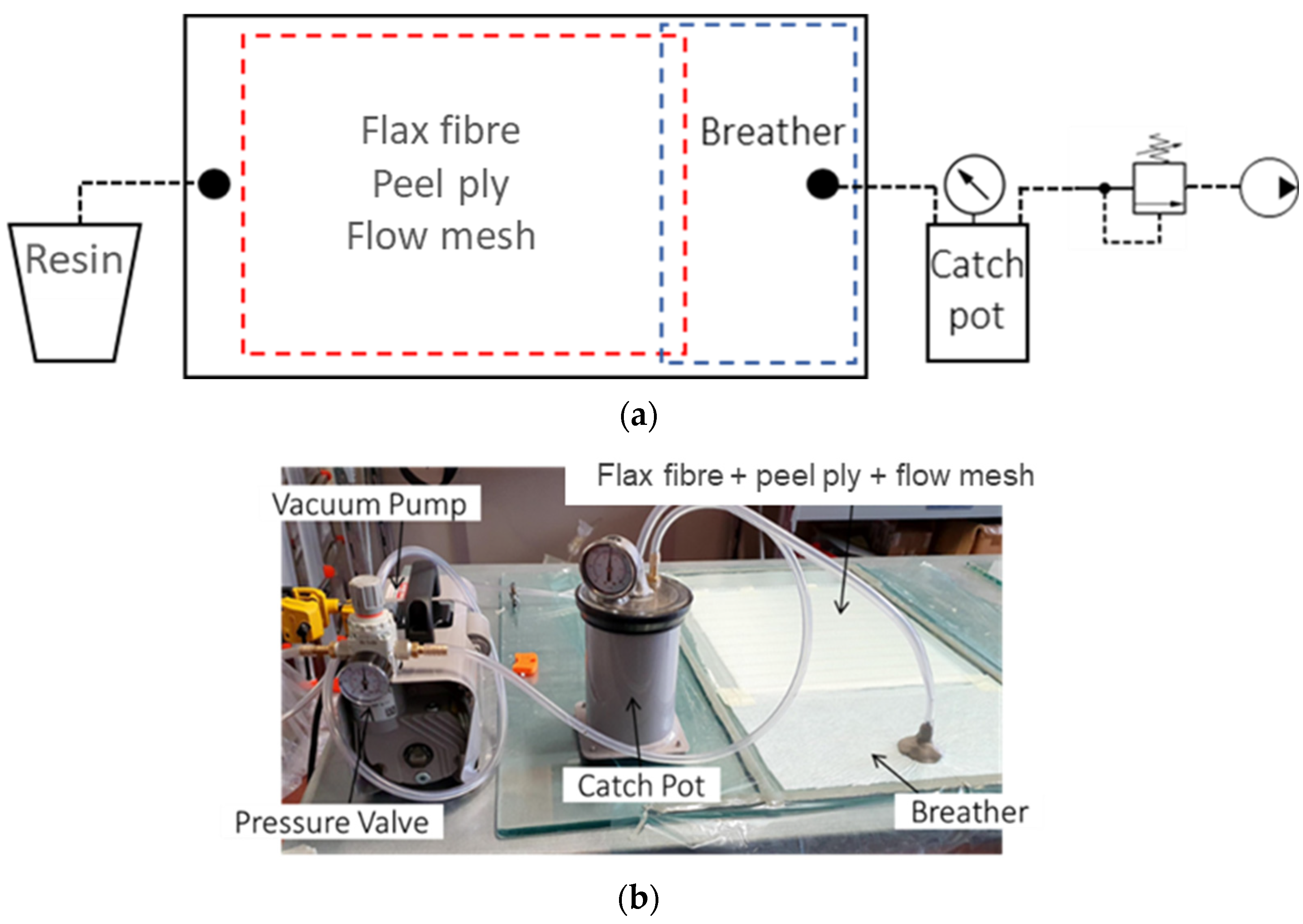
2.1.2. Fabrication of the Laminates
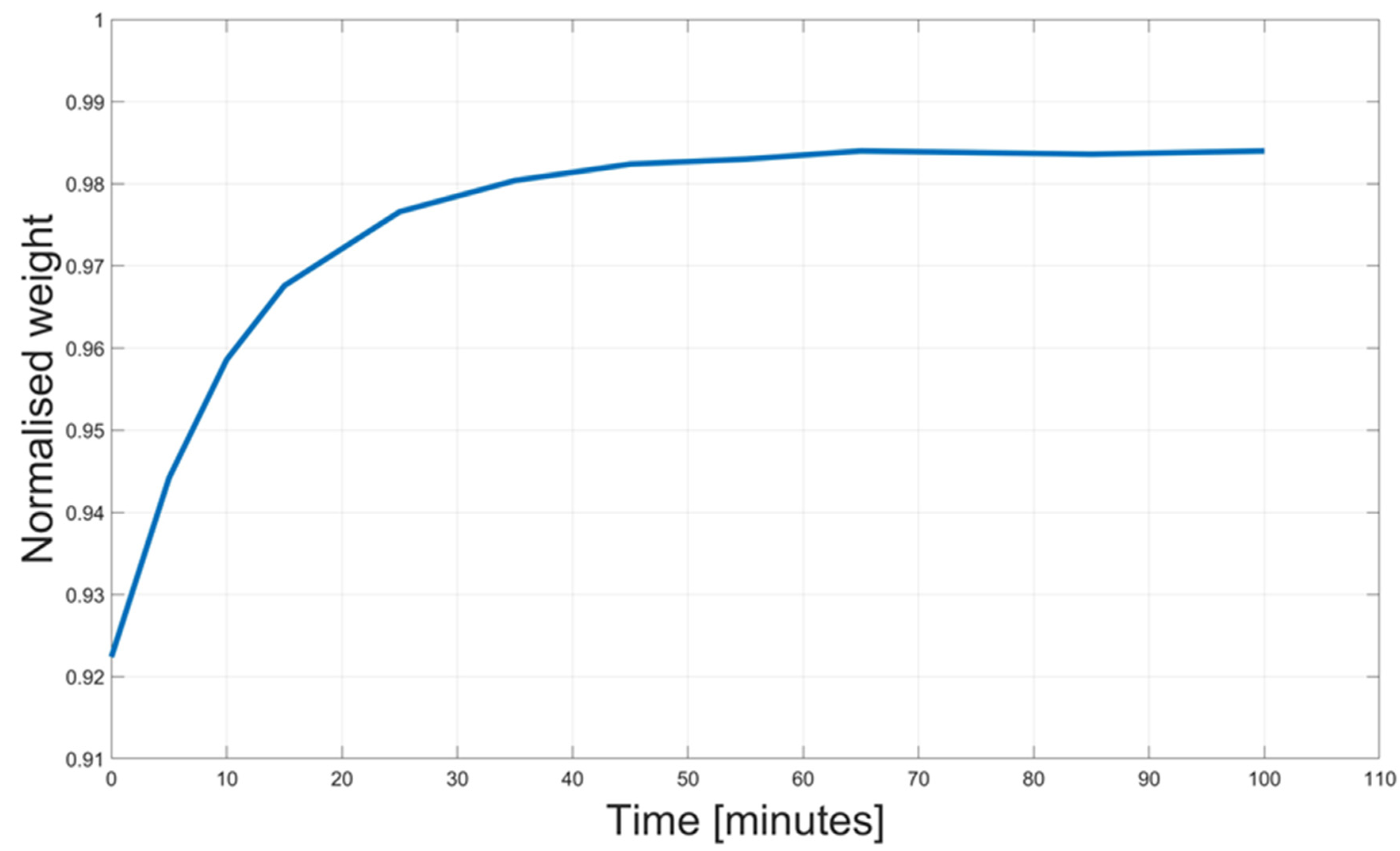
2.1.3. Dried and Undried Laminates
2.2. Mechanical Properties
2.2.1. Tensile Tests
2.2.2. Flexural Tests
2.2.3. Impacts
2.3. Tomography
3. Results and Discussion
3.1. Tomography
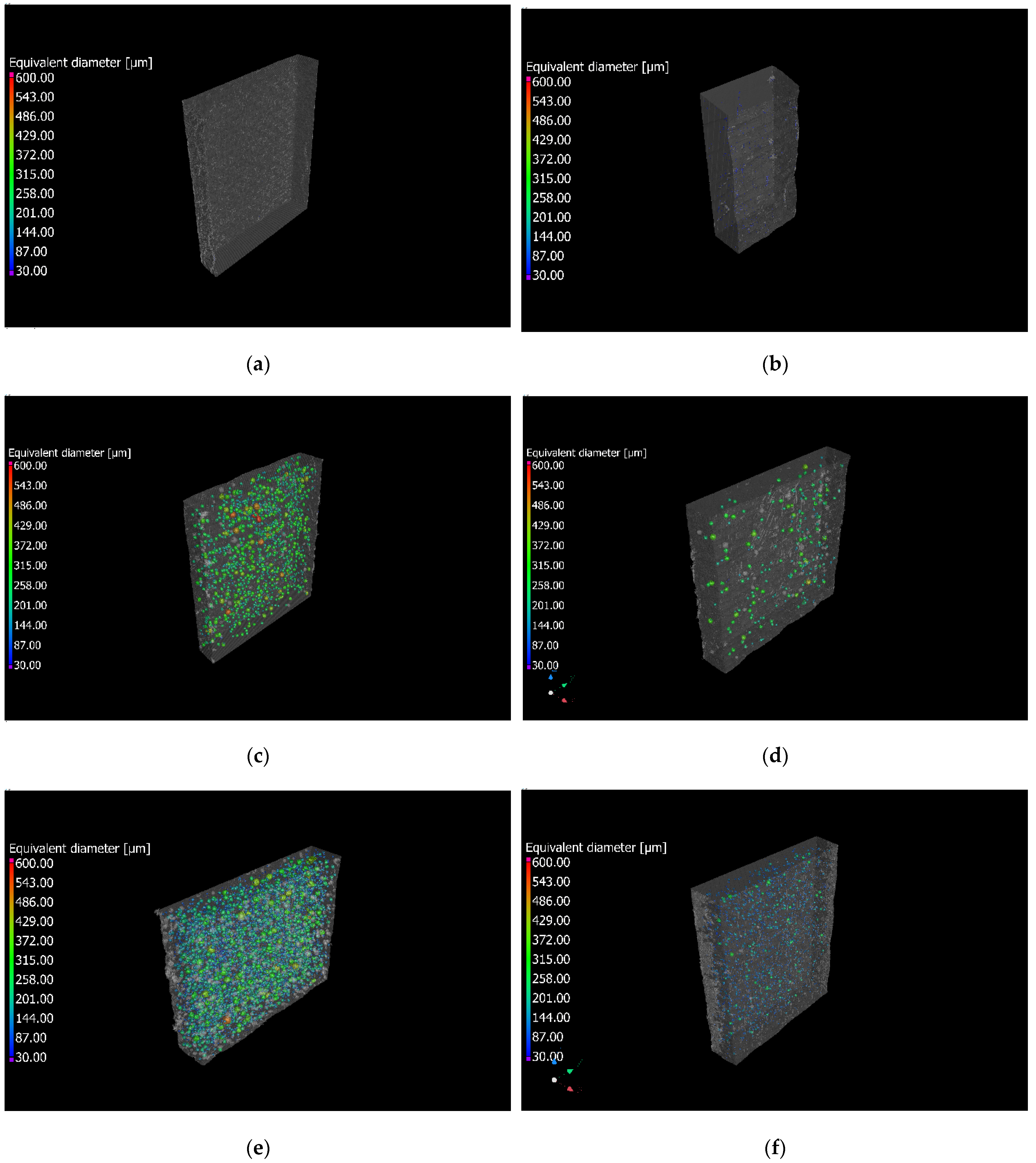
Porosity Analysis
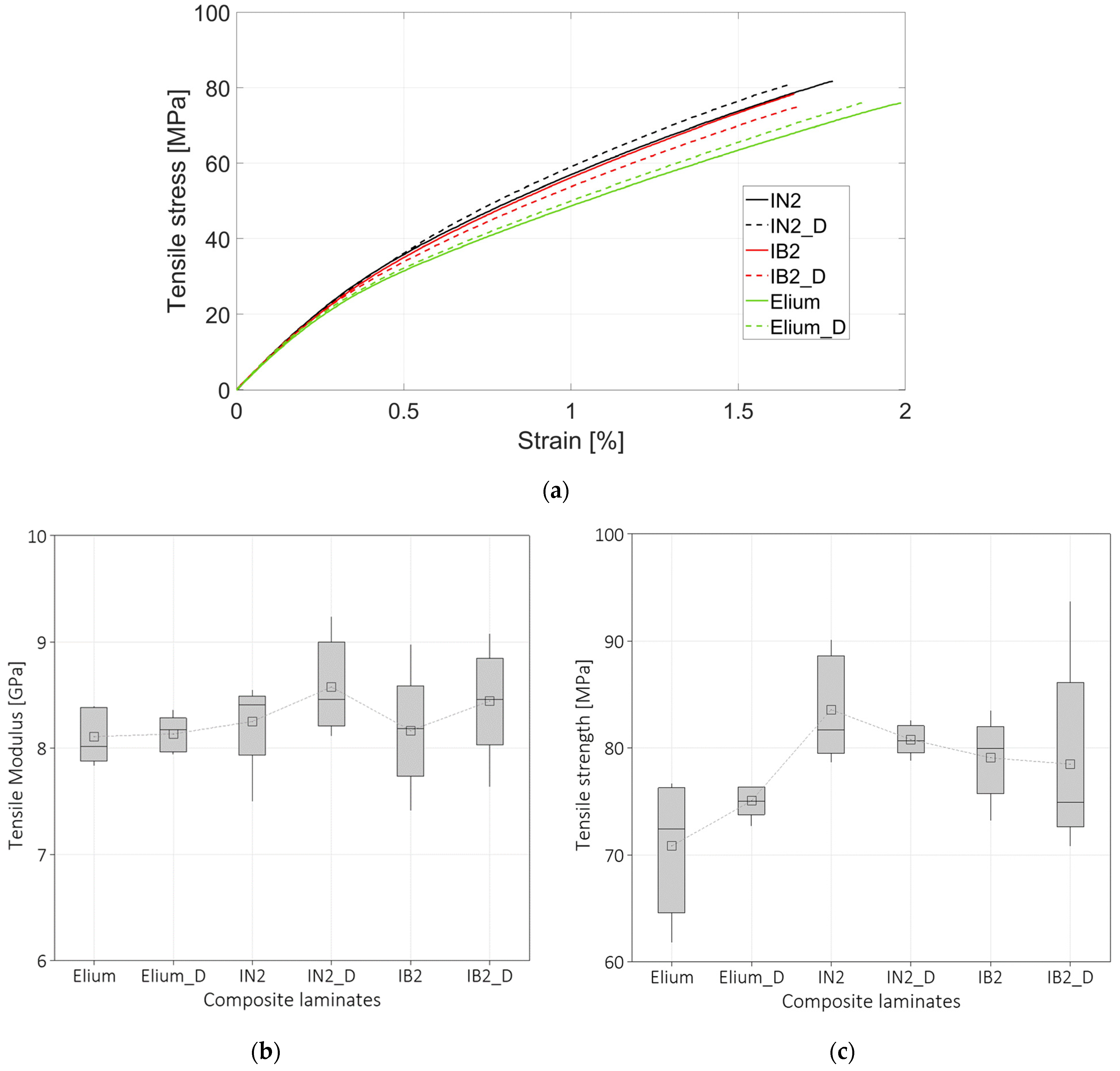
3.2. Tensile Tests
3.3. Flexural Tests
3.4. Out-of-Plane Impacts
3.4.1. Perforation Tests
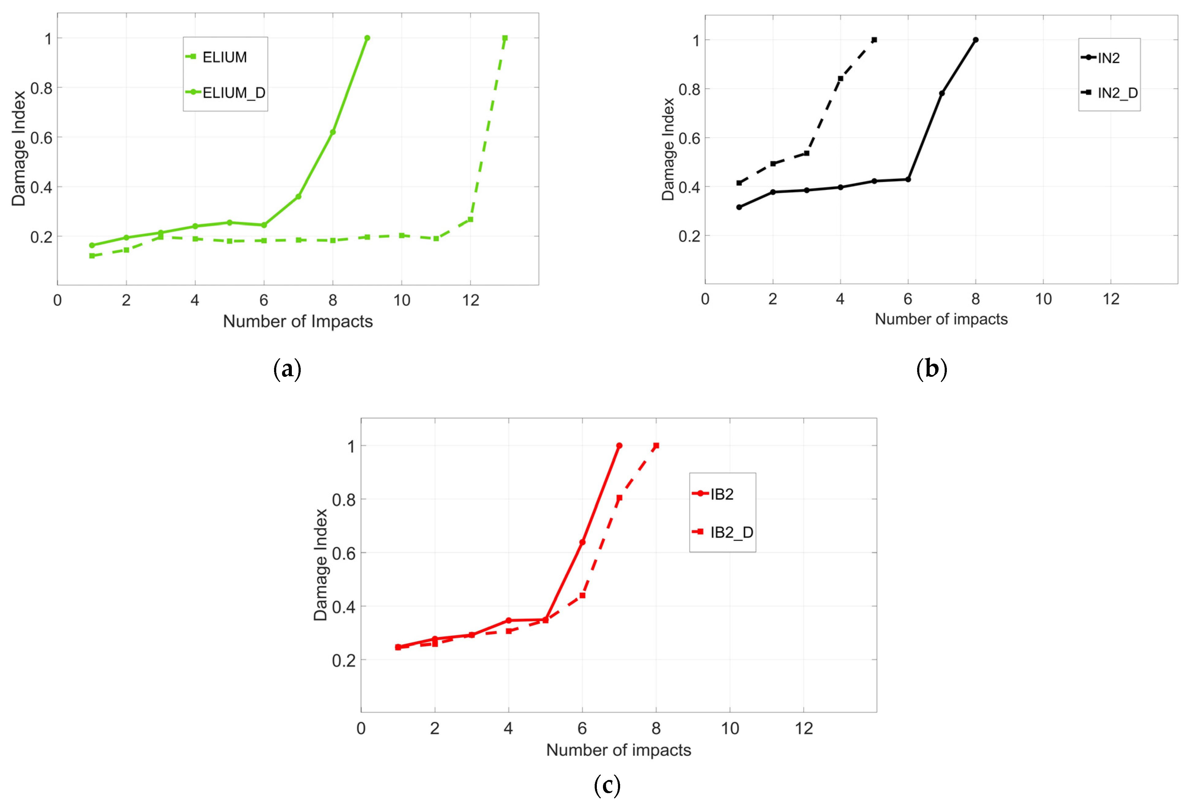
3.4.2. Repeated Impacts
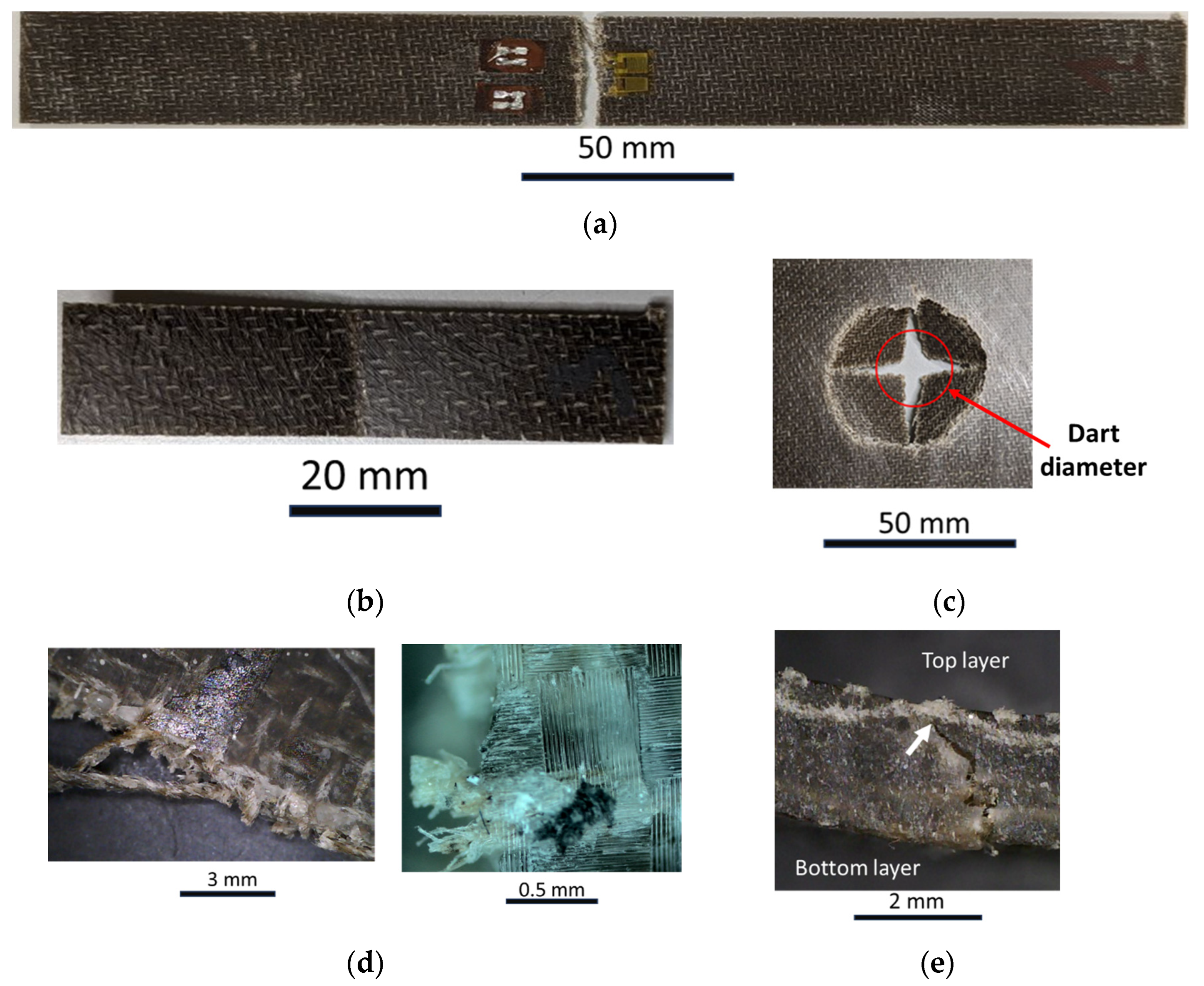
3.5. Failure Surfaces
3.6. Discussion
4. Conclusions
- The flax fabric in the lab environment at a relative humidity between 30% and 40% embeds an average moisture content of 6.1 wt.%.
- The CT analysis shows that the laminates fabricated with the dried fibers present a porosity close to 0% for all the analyzed cases. IN2 and IB2 resins present a porosity of 0.4% after drying the fibers, whereas they present a porosity of 2.4% and 4.6% by using undried fibers. On the other hand, composite laminates prepared with Elium resin present a value close to 0% for both dried and undried fibers.
- The tensile tests show that there is no significant difference among Young’s moduli for the different laminates. The average value of the modulus is 8.5 GPa. Composite laminates prepared with Elium present a lower strength compared to IB2 and IN2 laminates, approximately 8% less.
- The flexural tests showed that composite laminates prepared with Elium resin present a flexural modulus lower than 15% compared to composite laminates prepared with IN2 and IB2-based laminates. While the strength of the laminates prepared with Elium and IB2 is 10% lower compared to the conventional epoxy resin IN2.
- Impact tests at perforation showed that the laminates prepared with the three different resins and both dried and undried fibers present the same mechanical response. The laminates prepared with Elium resin can absorb higher impact energy due to the larger deformations these laminates can bear. Further, they can better absorb the repeated impacts.
Author Contributions
Funding
Data Availability Statement
Acknowledgments
Conflicts of Interest
References
- Koumoulos, E.P.; Trompeta, A.F.; Santos, R.M.; Martins, M.; dos Santos, C.M.; Iglesias, V.; Böhm, R.; Gong, G.; Chiminelli, A.; Verpoest, I.; et al. Research and Development in Carbon Fibers and Advanced High-Performance Composites Supply Chain in Europe: A Roadmap for Challenges and the Industrial Uptake. J. Compos. Sci. 2019, 3, 86. [Google Scholar] [CrossRef]
- European Parliament and of the Council. Directive 2000/53/EC of the European Parliament and of the Council of 18 September 2000 on End-of Life Vehicles. Off. J. Eur. Union 2000, L 269, 34–43. [Google Scholar]
- European Parliament and of the Council. Directive 2005/64/EC of the European Parliament and of the Council of 26 October 2005 on the Type-Approval of Motor Vehicles with Regard to Their Reusability, Recyclability and Recoverability and Amending Council Directive 70/156/EEC. Off. J. Eur. Union 2005, L 310/10, 10–27. [Google Scholar]
- Niutta, C.B.; Tridello, A.; Ciardiello, R.; Belingardi, G.; Paolino, D.S. Assessment of Residual Elastic Properties of a Damaged Composite Plate with Combined Damage Index and Finite Element Methods. Appl. Sci. 2019, 9, 2579. [Google Scholar] [CrossRef]
- Ciampaglia, A.; Ciardiello, R.; Cesano, F.; Belingardi, G.; Brunella, V. Multifunctional material design for strain sensing: Carbon black effect on mechanical and electrical properties of polyamides. Compos. Struct. 2022, 304, 116373. [Google Scholar] [CrossRef]
- Muflikhun, M.A.; Yokozeki, T.; Aoki, T. The strain performance of thin CFRP-SPCC hybrid laminates for automobile structures. Compos. Struct. 2019, 220, 11–18. [Google Scholar] [CrossRef]
- Kočí, V.; Picková, E. Life Cycle Perspective of Liquid Epoxy Resin Use in the Automotive Industry. Pol. J. Environ. Stud. 2019, 29, 653–667. [Google Scholar] [CrossRef]
- European Parliament and of the Council. Directive 2009/125/EC of the European Parliament and of the Council of 21 October 2009 Establishing a Framework for the Setting of Ecodesign Requirements for Energy-Related Products. Off. J. Eur. Union 2009, L 285/15, 10–25. [Google Scholar]
- European Parliament and of the Council. Directive 2009/28/EC of the European Parliament and of the Council of 23 April 2009 on the Promotion of the Use of Energy Form Renewable Sources and Amending and Repealing Directives 2001/77/EC and 2003/30/EC. Off. J. Eur. Union 2009, L 140/16, 16–62. [Google Scholar]
- Ma, Y.; Yang, Y.; Sugahara, T.; Hamada, H. A Study on the Failure Behavior and Mechanical Properties of Unidirectional Fiber Reinforced Thermosetting and Thermoplastic Composites. Compos. B Eng. 2016, 99, 162–172. [Google Scholar] [CrossRef]
- Andrew, J.J.; Dhakal, H.N. Sustainable Biobased Composites for Advanced Applications: Recent Trends and Future Opportunities—A Critical Review. Compos. Part C Open Access 2022, 7, 100220. [Google Scholar] [CrossRef]
- Zhang, C.; Xue, J.; Yang, X.; Ke, Y.; Ou, R.; Wang, Y.; Madbouly, S.A.; Wang, Q. From Plant Phenols to Novel Bio-Based Polymers. Prog. Polym. Sci. 2022, 125, 101473. [Google Scholar] [CrossRef]
- Iadarola, A.; Di Matteo, P.; Ciardiello, R.; Gazza, F.; Lambertini, V.G.; Brunella, V.; Paolino, D.S. Quasi-static and dynamic response of cardanol bio-based epoxy resins: Effect of different bio-contents. Procedia Struct. Integr. 2023, 47, 383–397. [Google Scholar] [CrossRef]
- Derahman, A.; Abidin, Z.Z. Mechanical properties of bio-epoxy resins and synthetic epoxy resins blends. IOP Conf. Ser. Mater. Sci. Eng. 2021, 1176, 012005. [Google Scholar] [CrossRef]
- Gour, R.S.; Kodgire, V.V.; Badiger, M.V. Toughening of epoxy novolac resin using cardanol based flexibilizers. J. Appl. Polym. Sci. 2015, 133. [Google Scholar] [CrossRef]
- Terry, J.S.; Taylor, A.C. The properties and suitability of commercial bio-based epoxies for use in fiber-reinforced composites. J. Appl. Polym. Sci. 2021, 138, 50417. [Google Scholar] [CrossRef]
- Nikafshar, S.; Zabihi, O.; Hamidi, S.; Moradi, Y.; Barzegar, S.; Ahmadi, M.; Naebe, M. A renewable bio-based epoxy resin with improved mechanical performance that can compete with DGEBA. RSC Adv. 2017, 7, 8694–8701. [Google Scholar] [CrossRef]
- Cousins, D.S.; Suzuki, Y.; Murray, R.E.; Samaniuk, J.R.; Stebner, A.P. Recycling glass fiber thermoplastic composites from wind turbine blades. J. Clean. Product. 2019, 209, 1252–1263. [Google Scholar] [CrossRef]
- Bel Haj Frej, H.; Léger, R.; Perrin, D.; Ienny, P.; Gérard, P.; Devaux, J.F. Recovery and reuse of carbon fibre and acrylic resin from thermoplastic composites used in marine application. Resour. Conserv. Recycl. 2021, 173, 105705. [Google Scholar] [CrossRef]
- Allagui, S.; Mahi, A.; Rebiere, J.L.; Beyaoui, M.; Bouguecha, A.; Haddar, M. Effect of recycling cycles on the mechanical and damping properties of flax fibre reinforced elium composite: Experimental and numerical studies. J. Renew. Mat. 2021, 9, 695–721. [Google Scholar] [CrossRef]
- Bhudolia, S.K.; Joshi, S.C.; Bert, A.; Yi Di, B.; Makam, R.; Gohel, G. Flexural characteristics of novel carbon methylmethacrylate composites. Compos. Commun. 2019, 13, 129–133. [Google Scholar] [CrossRef]
- Kazemi, M.E.; Shanmugam, L.; Lu, D.; Wang, X.; Wang, B.; Yang, J. Mechanical properties and failure modes of hybrid fiber reinforced polymer composites with a novel liquid thermoplastic resin, Elium®. Compos. Part A Appl. Sci. Manuf. 2019, 125, 105523. [Google Scholar] [CrossRef]
- Bhudolia, S.K.; Gohel, G.; Leong, K.F.; Joshi, S.C. Damping, impact and flexural performance of novel carbon/Elium® thermoplastic tubular composites. Compos. Part B Eng. 2020, 203, 108480. [Google Scholar] [CrossRef]
- Bhudolia, S.K.; Perrotey, P.; Joshi, S.C. Mode I fracture toughness and fractographic investigation of carbon fibre composites with liquid Methylmethacrylate thermoplastic matrix. Compos. Part B Eng. 2018, 134, 246–253. [Google Scholar] [CrossRef]
- Kazemi, M.E.; Shanmugam, L.; Li, Z.; Ma, R.; Yang, L.; Yang, J. Low-velocity impact behaviors of a fully thermoplastic composite laminate fabricated with an innovative acrylic resin. Compos. Struct. 2020, 250, 112604. [Google Scholar] [CrossRef]
- Kinvi-Dossou, G.; Matadi Boumbimba, R.; Bonfoh, N.; Garzon-Hernandez, S.; Garcia-Gonzalez, D.; Gerard, P. Innovative acrylic thermoplastic composites versus conventional composites: Improving the impact performances. Compos. Struct. 2019, 217, 1–13. [Google Scholar] [CrossRef]
- Matadi Boumbimba, R.; Coulibaly, M.; Khabouchi, A.; Kinvi-Dossou, G.; Bonfoh, N.; Gerard, P. Glass fibres reinforced acrylic thermoplastic resin-based tri-block copolymers composites: Low velocity impact response at various temperatures. Compos. Struct. 2017, 160, 939–951. [Google Scholar] [CrossRef]
- Bhudolia, S.K.; Gohel, G.; Kah Fai, L.; Barsotti, R.J. Fatigue response of ultrasonically welded carbon/Elium® thermoplastic composites. Mater. Lett. 2020, 264, 127362. [Google Scholar] [CrossRef]
- Shanmugam, L.; Kazemi, M.E.; Yang, J. Improved Bonding Strength Between Thermoplastic Resin and Ti Alloy with Surface Treatments by Multi-step Anodization and Single-step Micro-arc Oxidation Method: A Comparative Study. ES Mater. Manufact. 2019, 3, 57–65. [Google Scholar] [CrossRef]
- Shanmugam, L.; Kazemi, M.E.; Rao, Z.; Yang, L.; Yang, J. On the metal thermoplastic composite interface of Ti alloy/UHMWPE-Elium® laminates. Compos. Part B Eng. 2020, 181, 107578. [Google Scholar] [CrossRef]
- Murray, R.E.; Roadman, J.; Beach, R. Fusion joining of thermoplastic composite wind turbine blades: Lap-shear bond characterization. Renew. Energy 2019, 140, 501–512. [Google Scholar] [CrossRef]
- Gohel, G.; Bhudolia, S.K.; Kantipudi, J.; Leong, K.F.; Barsotti, R.J. Ultrasonic welding of novel Carbon/Elium® with carbon/epoxy composites. Compos. Commun. 2020, 22, 100463. [Google Scholar] [CrossRef]
- Shanmugam, L.; Kazemi, M.E.; Rao, Z.; Lu, D.; Wang, X.; Wang, B. Enhanced Mode I fracture toughness of UHMWPE fabric/thermoplastic laminates with combined surface treatments of polydopamine and functionalized carbon nanotubes. Compos. Part B Eng. 2019, 178, 107450. [Google Scholar] [CrossRef]
- Han, N.; Baran, I.; Zanjani, J.S.M.; Yuksel, O.; An, L.L.; Akkerman, R. Experimental and computational analysis of the polymerization overheating in thick glass/Elium® acrylic thermoplastic resin composites. Compos. Part B Eng. 2020, 202, 108430. [Google Scholar] [CrossRef]
- Gebhardt, M.; Manolakis, I.; Chatterjee, A.; Kalinka, G.; Deubener, J.; Pfnür, H. Reducing the raw material usage for room temperature infusible and polymerisable thermoplastic CFRPs through reuse of recycled waste matrix material. Compos. Part B Eng. 2021, 216, 108877. [Google Scholar] [CrossRef]
- Bhudolia, S.K.; Perrotey, P.; Joshi, S.C. Optimizing Polymer Infusion Process for Thin Ply Textile Composites with Novel Matrix System. Materials 2017, 10, 293. [Google Scholar] [CrossRef]
- Ciardiello, R.; Fiumarella, D.; Belingardi, G. Enhancement of the Mechanical Performance of Glass-Fibre-Reinforced Composites through the Infusion Process of a Thermoplastic Recyclable Resin. Polymers 2023, 15, 3160. [Google Scholar] [CrossRef]
- Boursier Niutta, C.; Ciardiello, R.; Tridello, A.; Paolino, D.S. Epoxy and Bio-Based Epoxy Carbon Fiber Twill Composites: Comparison of the Quasi-Static Properties. Materials 2023, 16, 1601. [Google Scholar] [CrossRef]
- Lu, M.M.; Fuentes, C.A.; Willem Van Vuure, A. Moisture sorption and swelling of flax fibre and flax fibre composites. Compos. Part B Eng. 2022, 231, 109538. [Google Scholar] [CrossRef]
- Moudood, A.; Hall, W.; Öchsner, A.; Li, A.; Rahman, A.; Francucci, G. Effect of Moisture in Flax Fibres on the Quality of their Composites. J. Nat. Fibers 2019, 16, 209–224. [Google Scholar] [CrossRef]
- de Kergariou, C.; Le Duigou, A.; Popineau, A.; Gager, V.; Kervoelen, A.; Perriman, A.; Saidani-Scott, H.; Allegri, G.; Hallak Panzera, T.; Scarpa, F. Measure of porosity in flax fibres reinforced polylactic acid biocomposites. Compos. Part A Appl. Sci. Manuf. 2021, 141, 106183. [Google Scholar] [CrossRef]
- Moudood, A.; Rahman, A.; Mohammad Khanlou, H.; Hall, W.; Öchsner, A.; Francucci, G. Environmental effects on the durability and the mechanical performance of flax fiber/bio-epoxy composites. Compos. Part B Eng. 2019, 171, 284–293. [Google Scholar] [CrossRef]
- Thuault, A.; Eve, S.; Blond, D.; Bre, J.; Gomina, M. Effects of the hygrothermal environment on the mechanical properties of flax fibres. J. Compos. Mat. 2014, 48, 1699–1707. [Google Scholar] [CrossRef]
- Moudood, A.; Rahman, A.; Huq, N.M.L.; Öchsner, A.; Islam, M.M.; Francucci, G. Mechanical properties of flax fiber-reinforced composites at different relative humidities: Experimental, geometric, and displacement potential function approaches. Polym. Compos. 2020, 41, 4963–4973. [Google Scholar] [CrossRef]
- Van de Weyenberg, I.; Chi Truong, T.; Vangrimde, B.; Verpoest, I. Improving the properties of UD flax fibre reinforced composites by applying an alkaline fibre treatment. Compos. Part A Appl. Sci. Manufac. 2006, 37, 1368–1376. [Google Scholar] [CrossRef]
- Amiri, A.; Ulven, C.A.; Huo, S. Effect of Chemical Treatment of Flax Fiber and Resin Manipulation on Service Life of Their Composites Using Time-Temperature Superposition. Polymers 2015, 7, 1965–1978. [Google Scholar] [CrossRef]
- IN2 Epoxy Infusion Resin. Available online: https://www.easycomposites.co.uk/in2-epoxy-infusion-resin (accessed on 6 December 2023).
- IB2 Epoxy Infusion Bio-Resin. Available online: https://www.easycomposites.co.uk/ib2-epoxy-infusion-bio-resin (accessed on 6 December 2023).
- Elium Infusion Resin. Available online: https://www.arkema.com/global/en/products/product-finder/product-range/incubator/elium_resins/ (accessed on 5 January 2024).
- Flax Fibres FLAXDRY-BL200. Available online: https://eco-technilin.com/en/flaxdry/52-L-FLAXDRY-BL200-30.html (accessed on 6 December 2023).
- Charlet, K.; Jernot, J.P.; Breard, J.; Gomina, M. Scattering of morphological and mechanical properties of flax fibres. Ind. Crop. Prod. 2010, 32, 220–224. [Google Scholar] [CrossRef]
- Coroller, G.; Lefeuvre, A.; Duigou, A.L.; Bourmaud, A.; Ausias, G.; Gaudry, T. Effect of flax fibres individualisation on tensile failure of flax/epoxy unidirectional composite. Compos. Part A 2013, 51, 62–70. [Google Scholar] [CrossRef]
- ASTM D3039; Standard Test Method for Tensile Properties of Polymer Matrix Composite Materials. ASTM International: West Conshohocken, PA, USA, 2016.
- ASTM D790; Standard Test Methods for Flexural Properties of Unreinforced and Reinforced Plastics and Electrical Insulating Materials. ASTM International: West Conshohocken, PA, USA, 2017.
- ASTM D5628-18; Standard Test Method for Impact Resistance of Flat, Rigid Plastic Specimens by Means of a Falling Dart (Tup or Falling Mass). ASTM International: West Conshohocken, PA, USA, 2016.
- Belingardi, G.; Cavatorta, M.P.; Paolino, D.S. A new damage index to monitor the range of the penetration process in thick laminates. Compos. Sci. Technol. 2008, 68, 2646–2652. [Google Scholar] [CrossRef]
- Giammaria, V.; Del Bianco, G.; Raponi, E.; Fiumarella, D.; Ciardiello, R.; Boria, S.; Duddeck, F.; Belingardi, G. Material parameter optimization of flax/epoxy composite laminates under low-velocity impact. Compos. Struct. 2023, 321, 117303. [Google Scholar] [CrossRef]
- Ciardiello, R.; Boursier Niutta, C.; Tridello, A.; Paolino, D.S. Impact Response of Carbon Fiber Composites: Comparison between Epoxy and Bio-Based Epoxy Matrices. In Dynamic Response and Failure of Composite Materials; DRAF 2022. Lecture Notes in Mechanical Engineering; Lopresto, V., Papa, I., Langella, A., Eds.; Springer: Cham, Switzerland, 2022. [Google Scholar]


| Resin | Elium | IN2 | IB2 |
|---|---|---|---|
| Density (g/cm3) | 1.01 | 1.14 | 1.12 |
| Viscosity (mPa · s) | 100 | 325 | 185 |
| Young’s Modulus (GPa) | 2.6 | 3.0 | 2.8 |
| Tensile strength (Mpa) | 56 | 68 | 68 |
| Flexural Modulus (Gpa) | 2.9 | 3.3 | 2.8 |
| Flexural strength (Mpa) | 111 | 120 | 107 |
| Porosities (%) | ||
|---|---|---|
| Resin | Undried | Dried |
| Elium | 0.0 * | 0.0 * |
| IN2 | 2.3 (±0.1) | 0.4 (±0.05) |
| IB2 | 4.6 (±0.1) | 0.4 (±0.1) |
| Composite Laminate | Pros | Cons | Possible Applications |
|---|---|---|---|
| IN2 Resin |
|
|
|
| IB2 Resin |
|
|
|
| Elium Resin |
|
|
|
Disclaimer/Publisher’s Note: The statements, opinions and data contained in all publications are solely those of the individual author(s) and contributor(s) and not of MDPI and/or the editor(s). MDPI and/or the editor(s) disclaim responsibility for any injury to people or property resulting from any ideas, methods, instructions or products referred to in the content. |
© 2024 by the authors. Licensee MDPI, Basel, Switzerland. This article is an open access article distributed under the terms and conditions of the Creative Commons Attribution (CC BY) license (https://creativecommons.org/licenses/by/4.0/).
Share and Cite
Ciardiello, R.; Benelli, A.; Paolino, D.S. Static and Impact Properties of Flax-Reinforced Polymers Prepared with Conventional Epoxy and Sustainable Resins. Polymers 2024, 16, 190. https://doi.org/10.3390/polym16020190
Ciardiello R, Benelli A, Paolino DS. Static and Impact Properties of Flax-Reinforced Polymers Prepared with Conventional Epoxy and Sustainable Resins. Polymers. 2024; 16(2):190. https://doi.org/10.3390/polym16020190
Chicago/Turabian StyleCiardiello, Raffaele, Alessandro Benelli, and Davide Salvatore Paolino. 2024. "Static and Impact Properties of Flax-Reinforced Polymers Prepared with Conventional Epoxy and Sustainable Resins" Polymers 16, no. 2: 190. https://doi.org/10.3390/polym16020190