
Numerical Simulation and Experimental Verification of Melt-Spinning Parameters’ Effects on Multi-Leaf Hollow-Profiled Fiber Preparation

Abstract
:1. Introduction
2. Formulations and Numerical Simulations
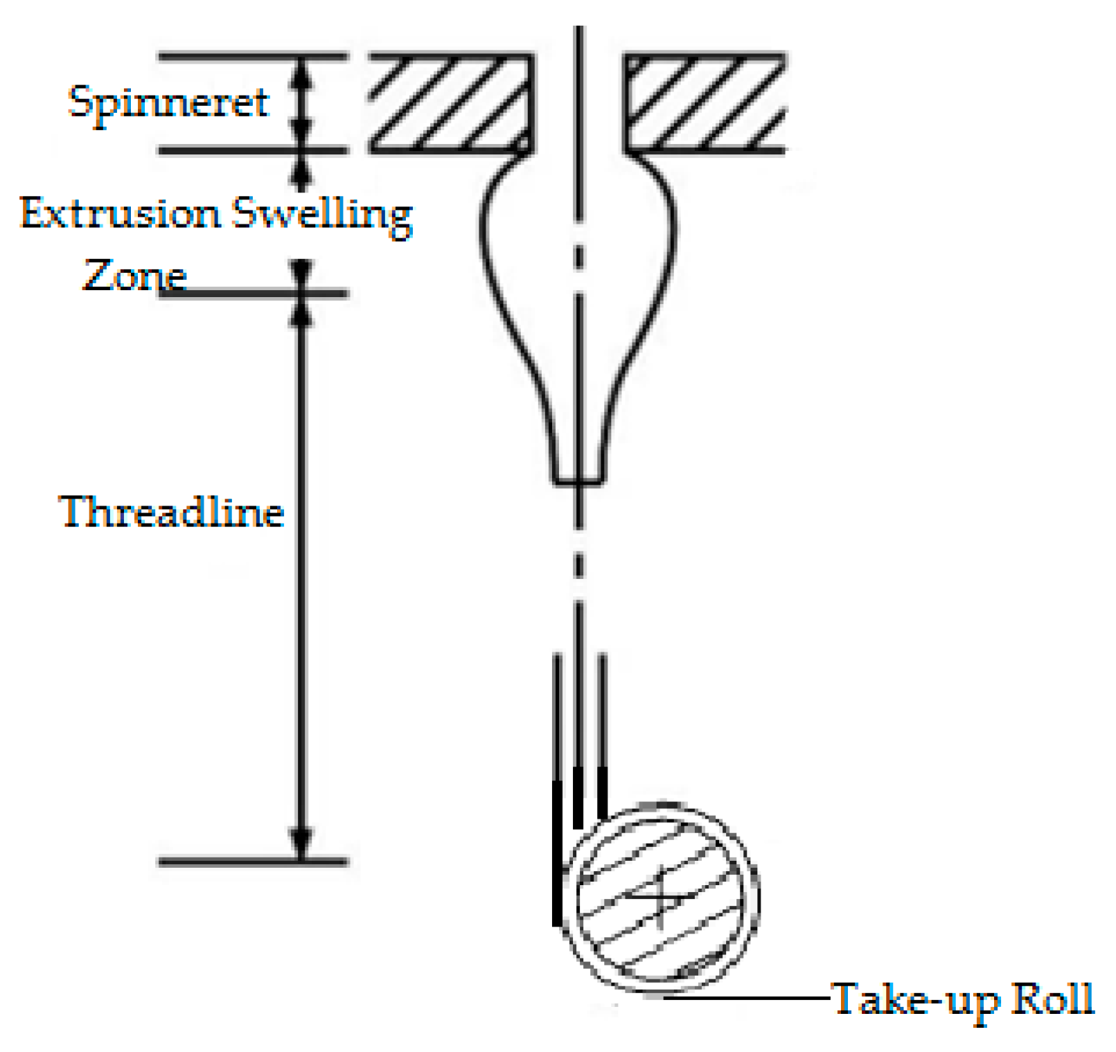
2.1. Dynamic Model for Spinning of Profiled Fibers
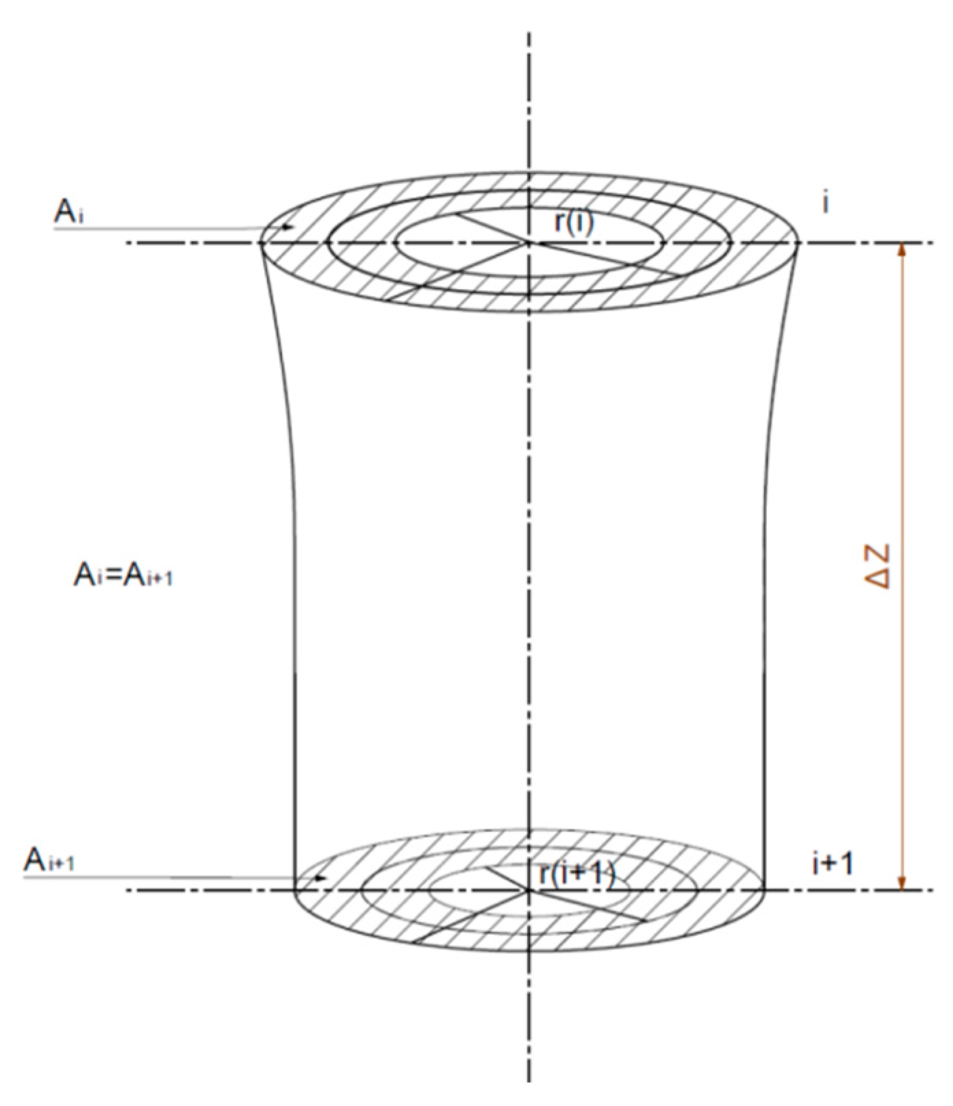
2.2. Deformation Dynamics of Cross-Section of Profiled Hollow Fibers
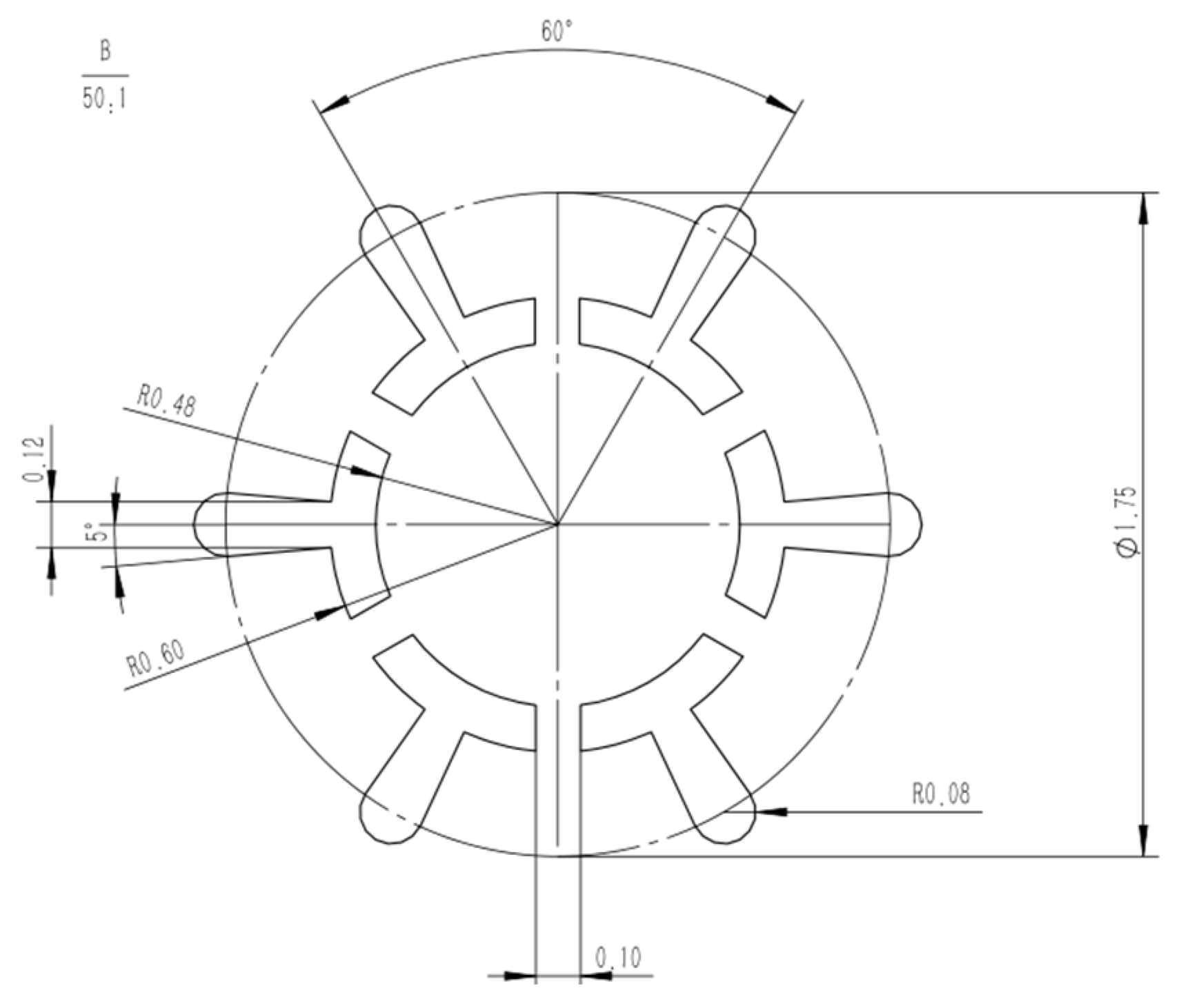
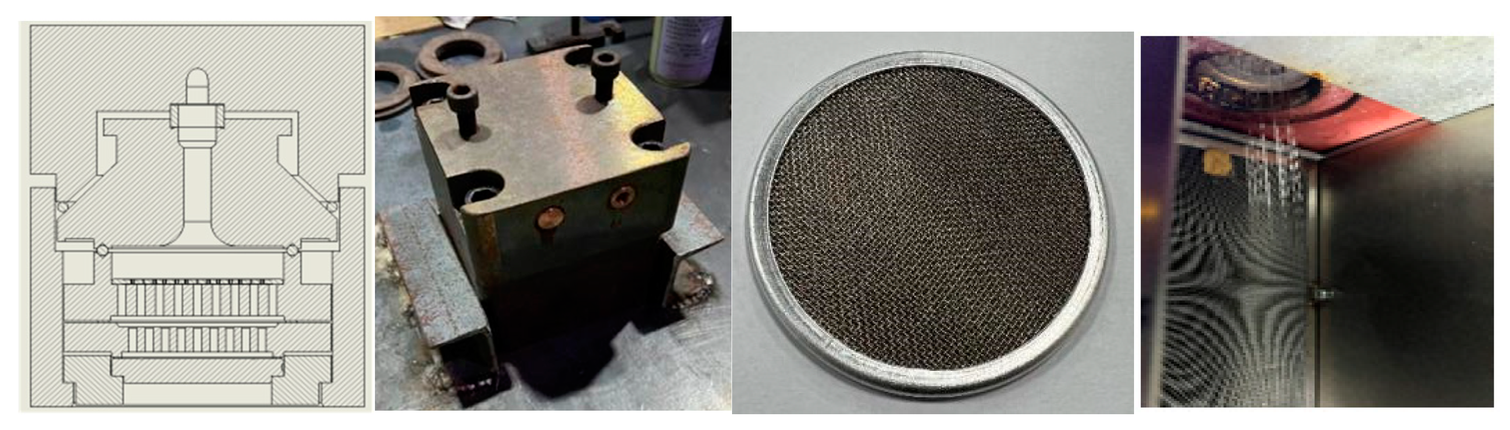
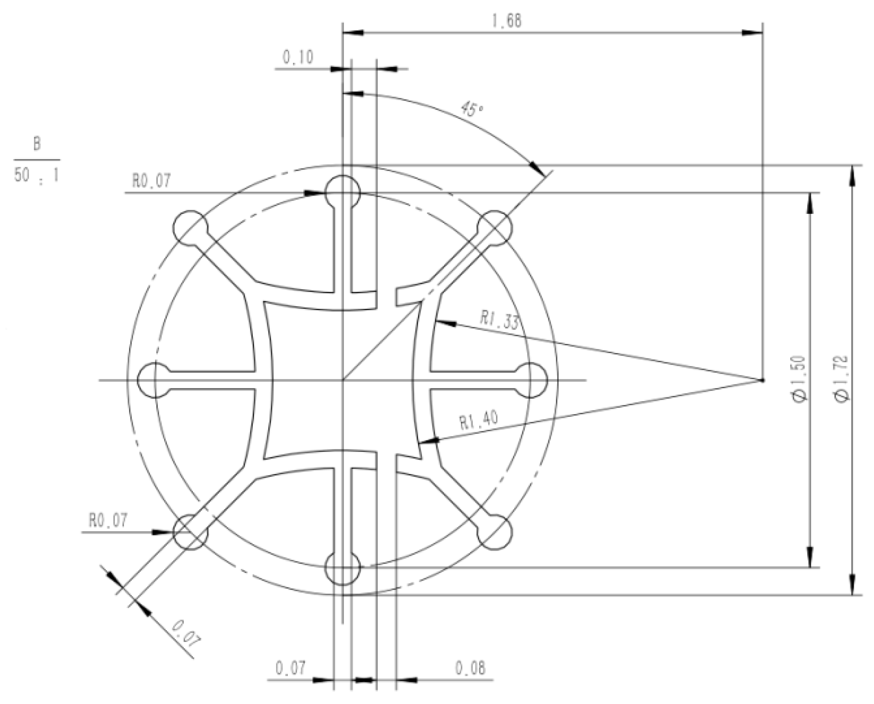
2.3. Design of Spinneret
2.4. Numerical Simulation of Melt Flow
- (1)
- Simulation results of pressure distribution
- (2)
- Simulation results of shear rate distribution
- (3)
- Simulation results of velocity distribution
- (4)
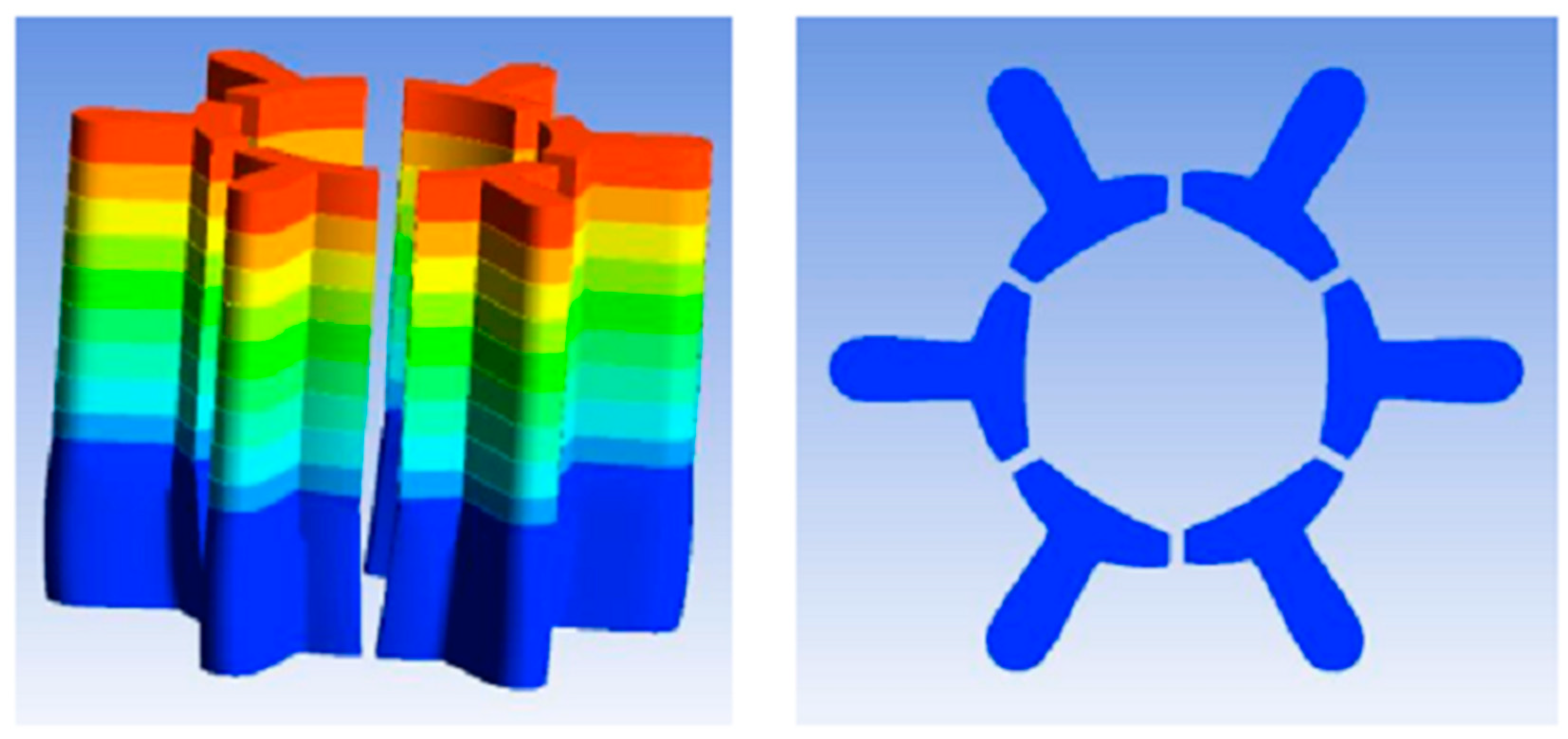
- Numerical simulation of the extrusion swell
3. Materials and Experiment
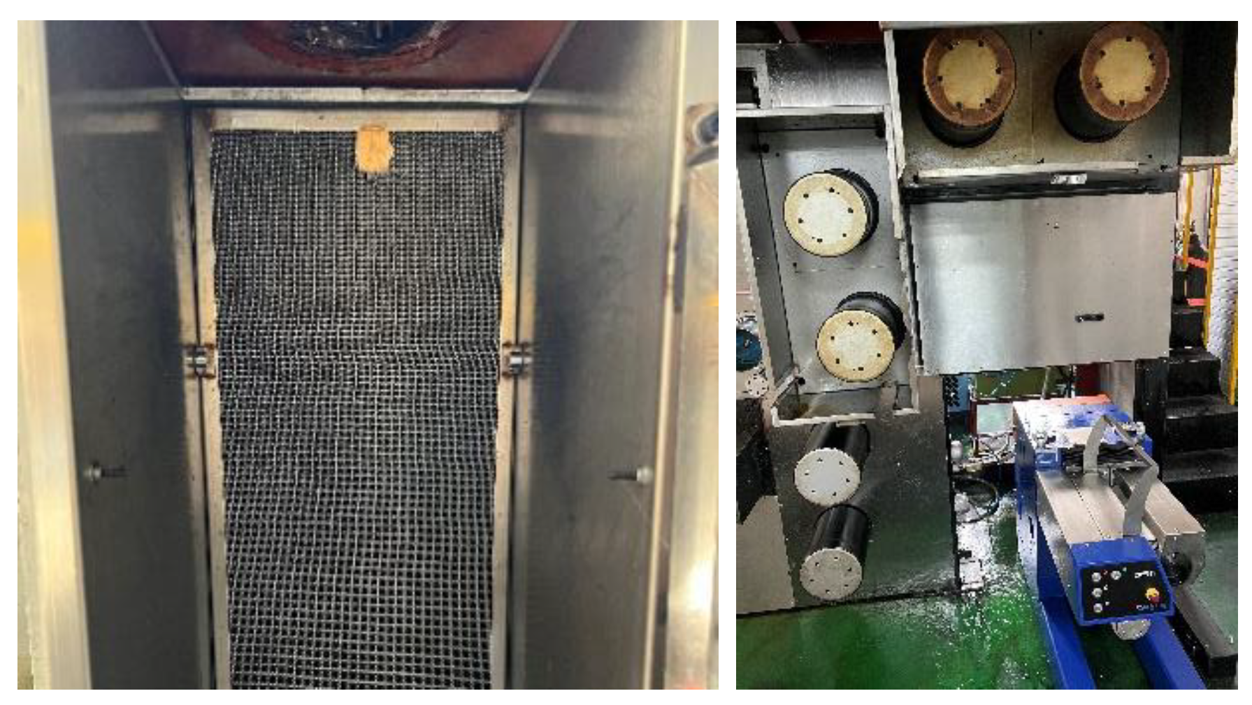
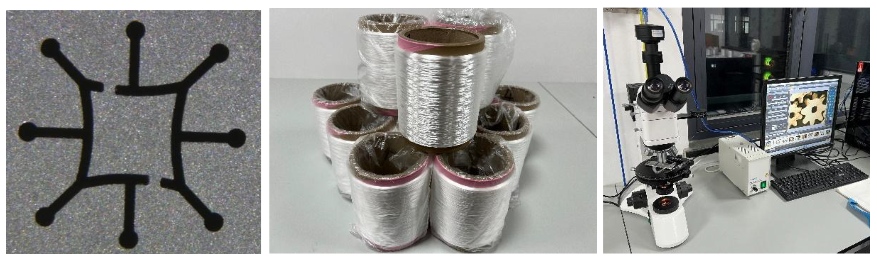
3.1. Fiber Preparation Equipment
3.2. Spinning Process Parameters
3.3. Melt Spinning
4. Application and Results
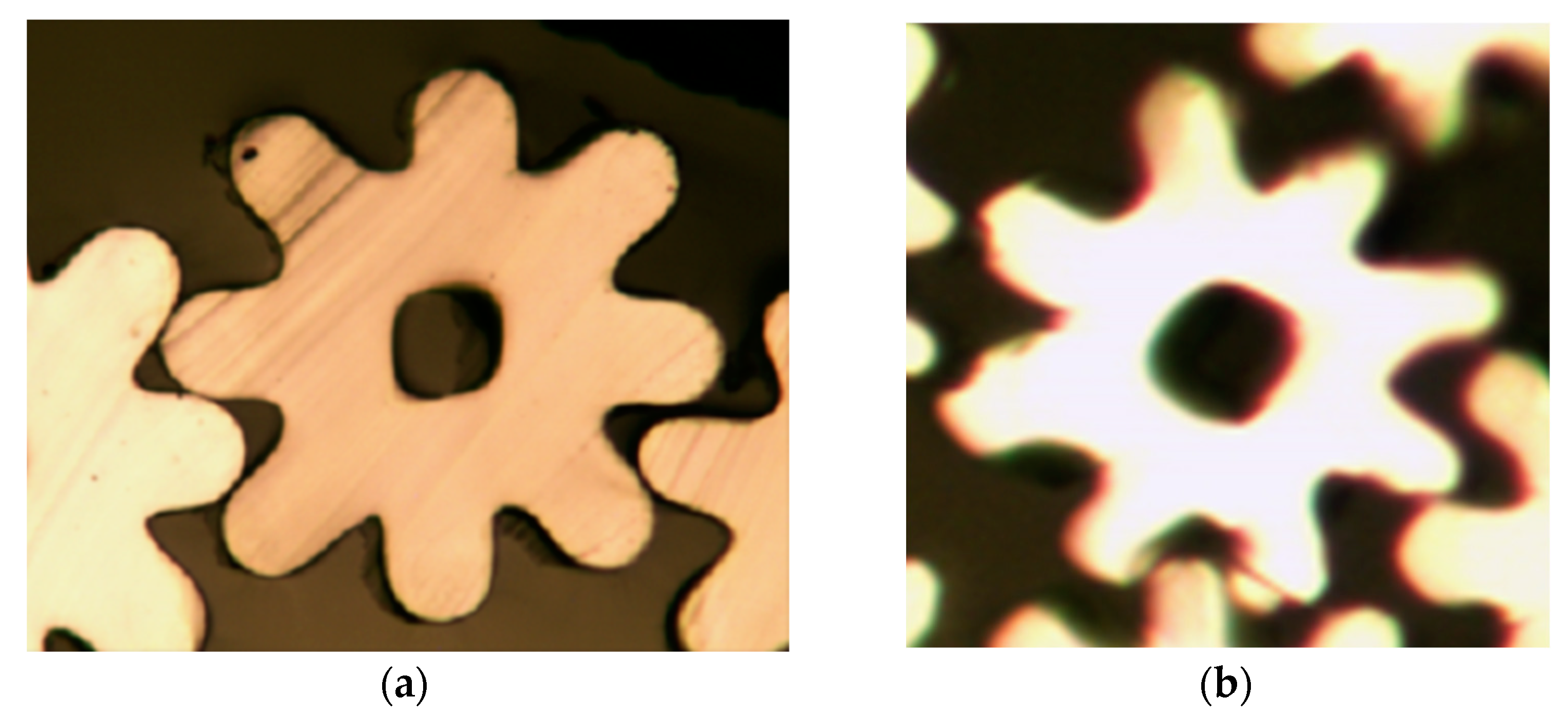
4.1. Design of Spinneret Micro-Hole for Eight-Leaf Square Hollow Profiled Fiber
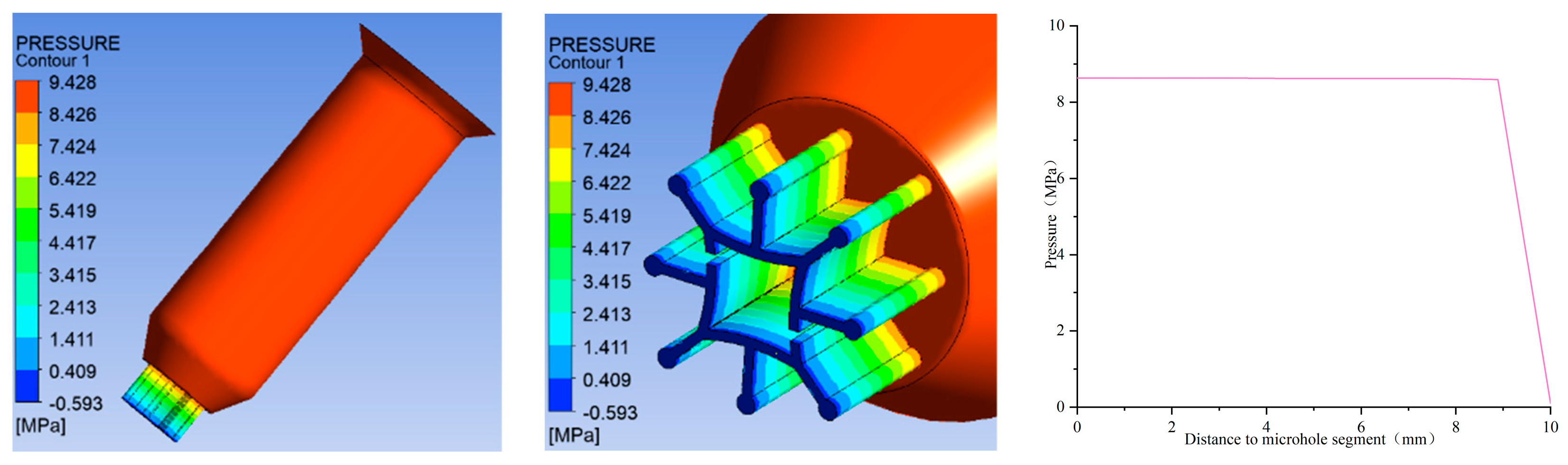
4.2. Numerical Simulation of Melt Flow
- (1)
- Pressure distribution
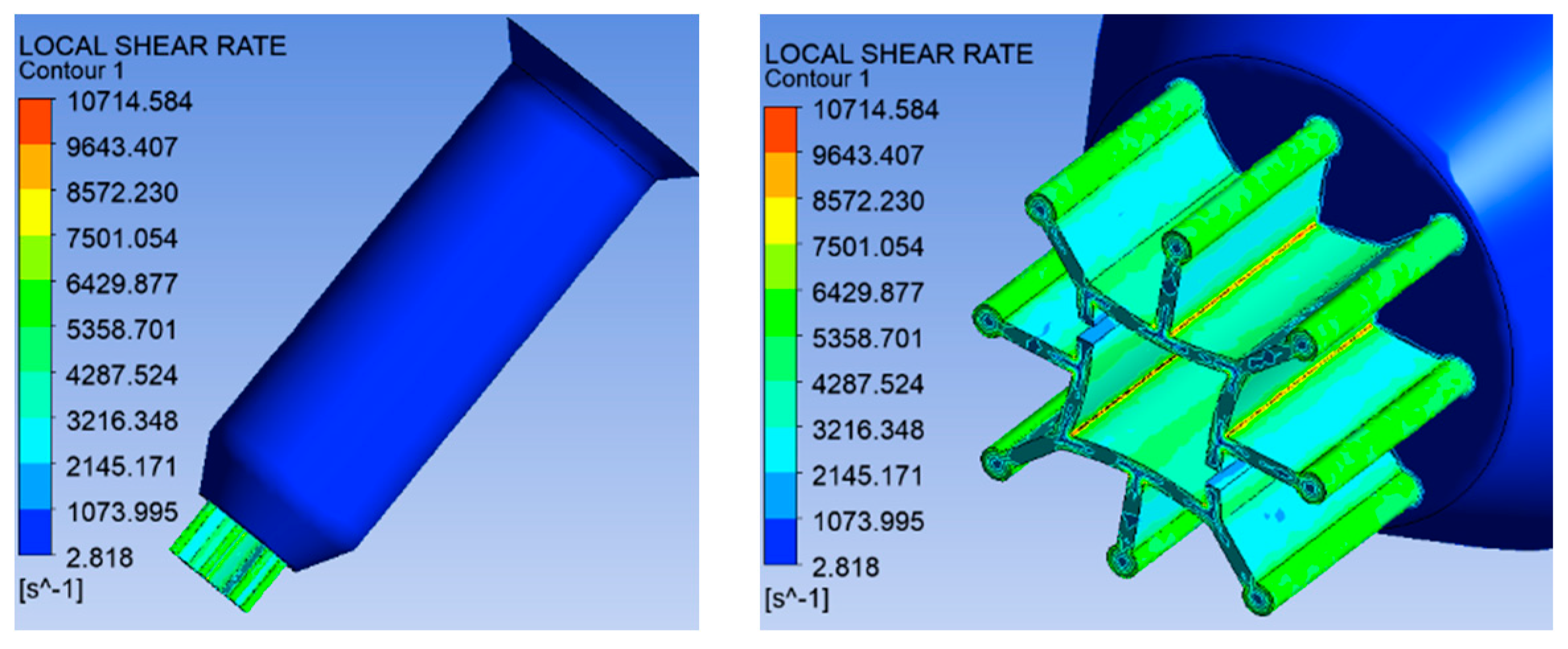
- (2)
- Shear rate distribution
- (3)
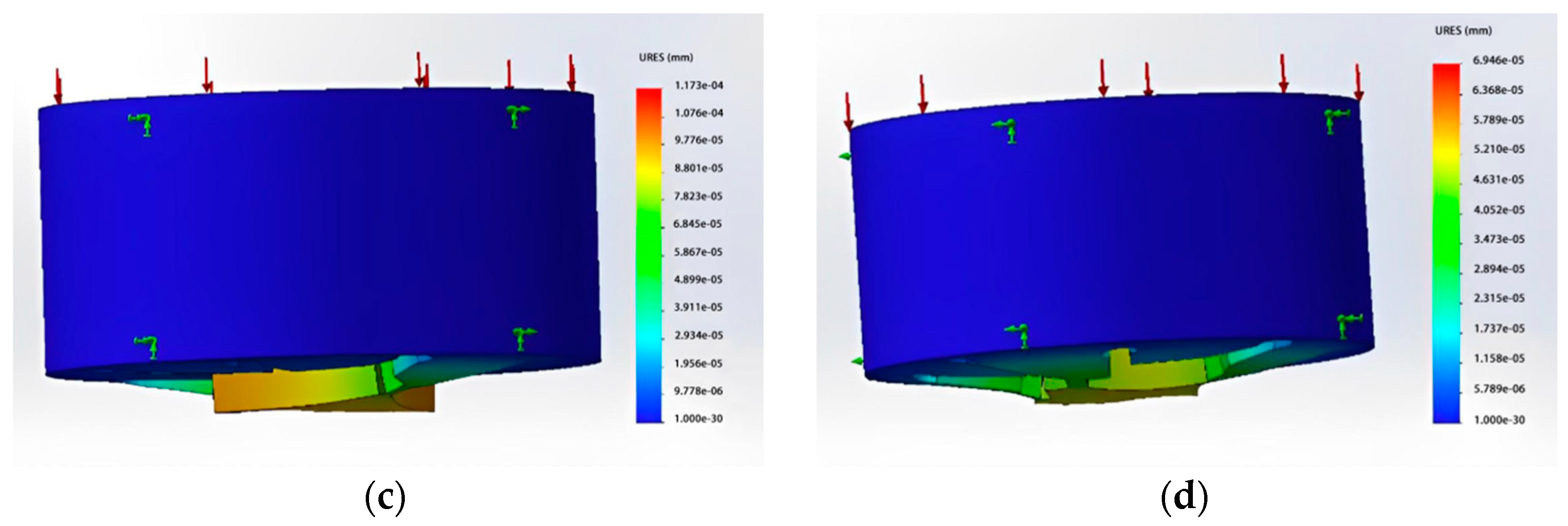
- Numerical simulation of the extrusion swell
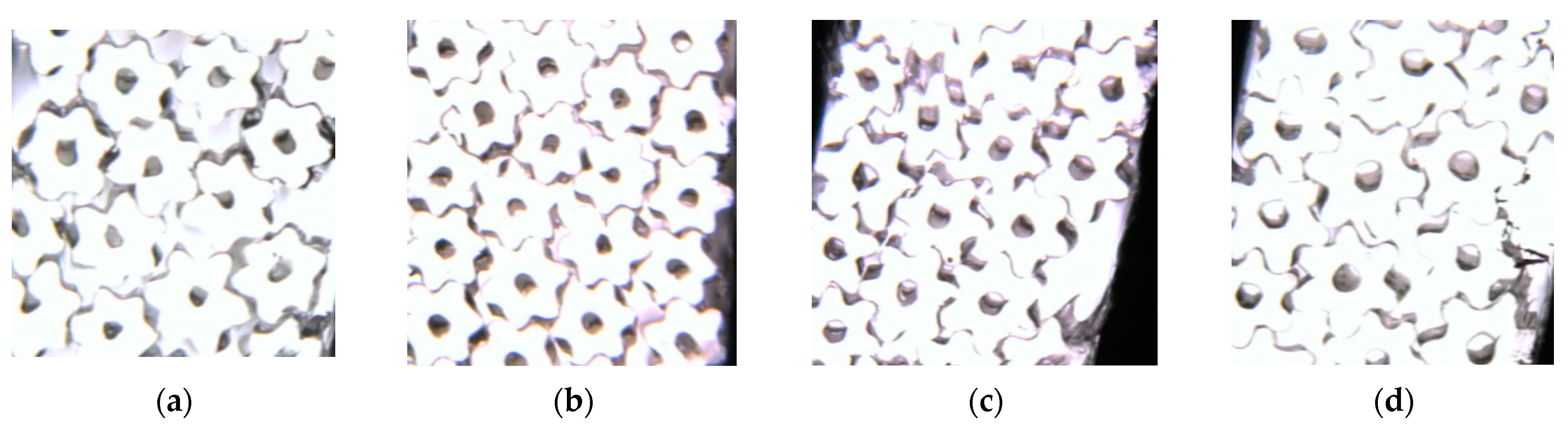
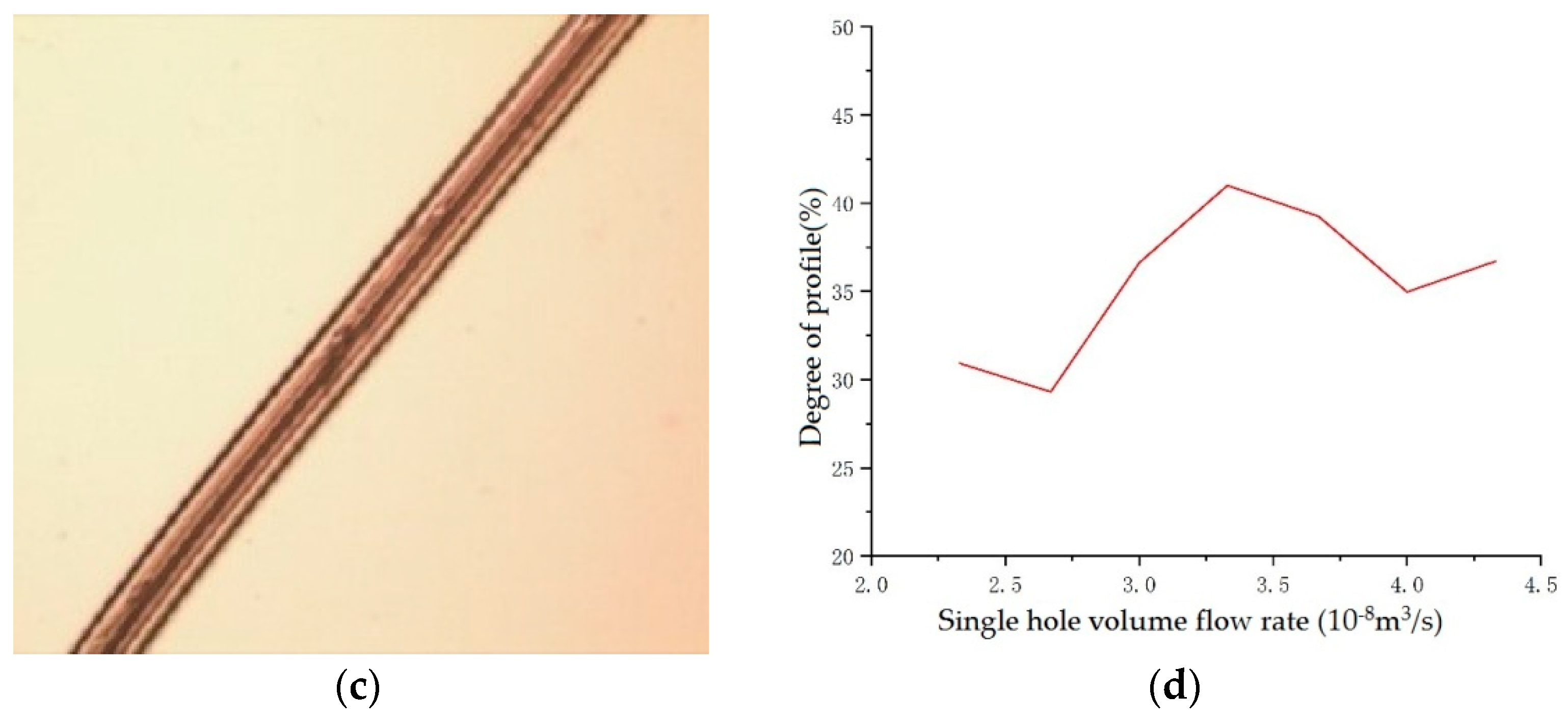
4.3. Results and Analysis
4.4. Performance Testing
- (1)
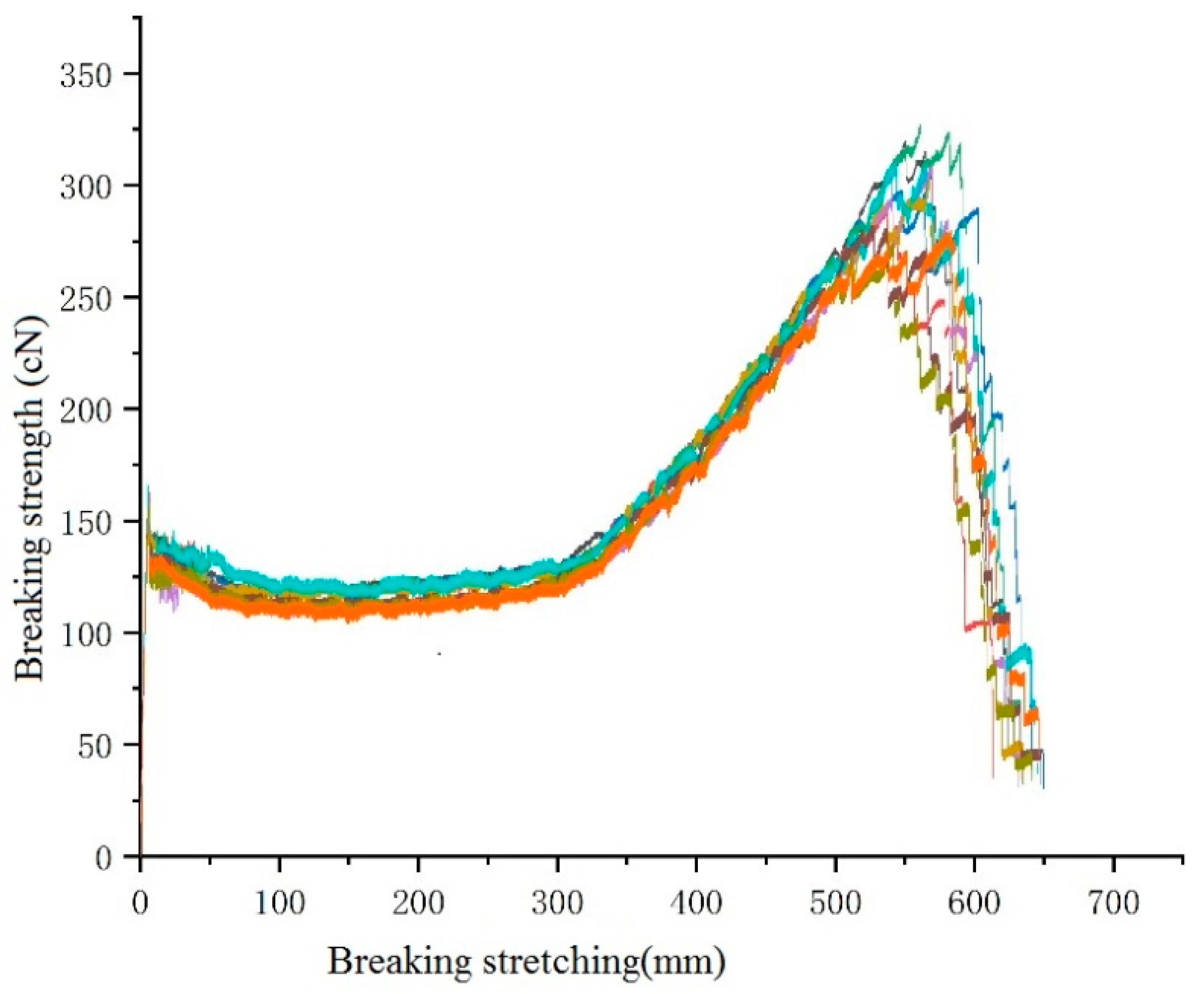
- Mechanical performance testing
- (2)
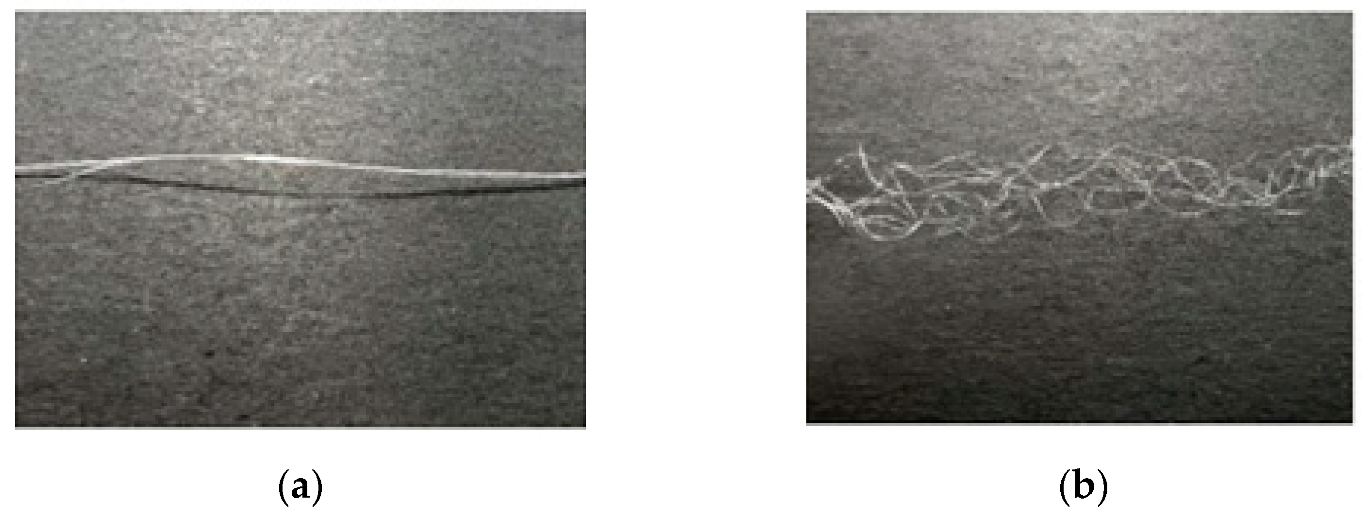
- Testing of Natural 3D Crimp Characteristics
5. Conclusion and Discussion
Supplementary Materials
Author Contributions
Funding
Institutional Review Board Statement
Data Availability Statement
Conflicts of Interest
References
- Zou, S.G.; Chi, R.Q.; Tao, G.P. The Development Status and Prospects of Differentiated Fibres. China Fibre Insp. 2005, 5, 31–33. [Google Scholar]
- Wang, J.P. Specializing Techniques for Fibres. Synth. Fibre China 2000, 2, 3–9. [Google Scholar]
- Li, M.W.; Wang, C.Y. Study on Structure Control and Performance of Mesophase Pitch-based Carbon Fibre. Carbon 1996, 4, 14–18. [Google Scholar]
- Shi, Y.; Zha, Q.F.; Liu, L. Melt spinning of asphalt based Y-shaped carbon fibres. New Carbon Mater. 1995, 3, 33–37. [Google Scholar]
- Huang, H. Research on Moisture Absorption and Perspiration Performance of Fabrics. Master’s Thesis, SuZhou University, Jiangsu, China, 2010. [Google Scholar]
- Li, P.S. Dyeing of Thermolite fibre knitted fabrics. Knitt. Ind. 2007, 8, 44–45. [Google Scholar]
- Gan, X.H.; Ma, X.J.; Liu, Q.; Cao, J.Y.; Liu, N.N.; Yang, C.C. Numerical simulation research of extrusion-forming process of cross fibres based on Polyflow. J. Text. Res. 2011, 32, 132–136. [Google Scholar]
- Zhao, Y.Z.; Zhang, Y.; Zhang, J.C. Study on the Wet Evaporation Performance of Coolmax Fabric Surface. Beijing Text. J. 2003, 1, 42–44. [Google Scholar]
- Jung, I.; Sang, S.K.; Tae, H.O. Effects of Spinning Conditions on Shape Changes of Trilobal-shaped Fibres. Text. Res. J. 2010, 80, 12–18. [Google Scholar] [CrossRef]
- Shen, H.B. The High Speed Spinning Hollow Fibre Tecnological Design and the Structure Performance Studies. Master’s Thesis, Suzhou University, Jiangsu, China, 2005. [Google Scholar]
- Yang, B. The Technology Design of Alkali-minimization Treatment for C-type Hollow Polyester Filament. Master’s Thesis, Donghua University, Shanghai, China, 2015. [Google Scholar]
- Wang, X. Study on Properties of Hollow Modified Polyester and ITS Knitted Fabrics. Master’s Thesis, Donghua University, Shanghai, China, 2011. [Google Scholar]
- Zhen, Z. AsahiKASEI: New hollow polyester fibre. Text. Appar. Wkly. Sci. Technol. Ed. 2000, 12, 16. [Google Scholar]
- Takarada, W.; Ito, H.; Kikutani, T.; Okui, N. Studies on high-speed melt spinning of noncircular cross-section fibres. I. Structural analysis of as-spun fibres. J. Appl. Polym. Sci. 2001, 80, 1575–1581. [Google Scholar] [CrossRef]
- Zhang, D.S.; Zhao, G.L.; Li, Y.L. Develop Modified Chemical Fibres and Stimulate Chemical Fibre Industry. China Synth. Fibre Ind. 1998, 29–32. [Google Scholar]
- Karaca, E.; Kahraman, N.; Omeroglu, S.; Becerir, B. Effects of Fibre Cross Sectional Shape and Weave Pattern on Thermal Comfort Properties of Polyester Woven Fabrics. Fibres Text. East. Eur. 2012, 92, 67–72. [Google Scholar]
- Lu, Y. Teijin Fibres: New octagonal polyester fibre. Melliand China 2013, 41, 16. [Google Scholar]
- Cao, Q.; Wang, T.L.; Shi, X.N.; Qiu, Z.C.; Ma, X. Study on the Preparation Process and Properties of Triangular three Hole Hollow Polypropylene Fibres. Text. Sci. Res. 2022, 8, 42–46. [Google Scholar]
- Qian, B.Z.; Yi, Z. Chemical Fibre Company Added New Products to Hollow Fibres. Synth. Fibre China 2022, 51, 11. [Google Scholar]
- Feng, P.; Pan, J.; Qi, H.; Yang, C.C. Studies on the Melt Spinning Process of Square 8-hole Hollow Polyester Fibre. Fibres Text. East. Eur. 2018, 26, 14–16. [Google Scholar] [CrossRef]
- OH, T.H.; Lee, M.S.; Kim, S.Y.; Shim, H.J. Studies on melt-spinning process of hollow fibres. J. Appl. Polym. Sci. 1998, 68, 1209–1217. [Google Scholar] [CrossRef]
- OH, T. Studies on melt spinning process of hollow polyethylene terephthalate fibres. Polym. Eng. Sci. 2006, 46, 609–616. [Google Scholar] [CrossRef]
- Lipscomb, G.G. The melt hollow fibre spinning process: Steady-state behavior, sensitivity and stability. Polym. Adv. Technol. 1994, 5, 745–758. [Google Scholar] [CrossRef]
- Ruckdashel, R.; Shim, E. Hollowness Variation with Die Wall Thickness in Melt-Spinning of Polypropylene Hollow Fibres. Fibres Polym. 2022, 23, 1256–1265. [Google Scholar] [CrossRef]
- Su, Y.Y.; Wei, S.P.; Wu, L.Y.; Lin, Y.T.; An, T.C.; Lin, W.P.; Chien, S.P.; Lin, Y.L. Shaping conjugated hollow fibres using a four-segmented arc spinneret. Polym. Eng. Sci. 2011, 51, 704–711. [Google Scholar] [CrossRef]
- Yang, C.; Qian, C.; Zhong, W.; Wang, Y.; Wang, H.P. The design and manufacture of profiled multi-channeled hollow polyester fibres. Fibres Polym. 2009, 10, 657–661. [Google Scholar] [CrossRef]
- Ma, W.Q.; Sun, H.Y. Fundamentals and Applications of Plastic Forming Simulation Software Technology; China Railway Publishing House: Beijing, China, 2006. [Google Scholar]
- Bird, R.B.; Stewart, W.E.; Lightfoot, E.N. Transport Phenomenn; Wiley: New York, NY, USA, 2002. [Google Scholar]
- Zhou, J. Study on the Computer Simulation of Polymer Mixing, Branch Reaction and Extrusion Processing Process. Ph.D. Thesis, Shanghai Jiao Tong University, Shanghai, China, 2010. [Google Scholar]
- Yang, C.C. Studies on Design, Manufacture and Applications of Spinneret for Melt-spinning Shaped Fibres. Ph.D. Thesis, Donghua University, Shanghai, China, 2008. [Google Scholar]
- Wang, C.S.; Zhao, R.H.; Han, Q.X.; Zhang, C.X.; Wang, H.P.; Zhang, Y.; Xiao, G. Model and Simulation of Polyethylene Terephthalate (PET) Hollow Fibre. J. Donghua Univ. 2009, 26, 387–392. [Google Scholar]
- Schaf, K. High performance new filtration design for spinning components. Text. Technol. Overseas 2000, 9, 21–24. [Google Scholar]
- Fu, B.T. Fine denier spinning components with all metal mesh structure. China Synth. Fibre Ind. 1995, 18, 53–55. [Google Scholar]
- Yang, S.L. The optimal metal mesh filter medium in spinning components. Melliand China 1997, 64. [Google Scholar]


| Parameters | Six-Leaf Hollow |
|---|---|
| Single-hole volume flow rate m3/s | 4.75 × 10⁻⁸ |
| Equivalent diameter mm | 0.228 |
| Shear rate m·s−1 | 2450.55 |
| Draw-down ratio | 265 |
| Parameters | Values |
|---|---|
| Non-Newtonian index n | 0.69 |
| Relaxation time s | 0.012 |
| Zero-shear viscosity Pa·s | 20 |
| Limit-shear viscosity Pa·s | 120 |
| Density kg·m−3 | 1.268 |
| Thermal conductivity w·m−1k−1 | 0.21 |
| Heat capacity J·kg·k−1 | 3.452 |
| Name | Six-Leaf Hollow |
|---|---|
| Filter screen, MPa | 0.691 |
| Distributinon plate, MPa | 0.008 |
| Spinneret plate, MPa | 6.371 |
| Total pressure drop, MPa | 7.07 |
| Items | Six-Leaf Hollow | |
|---|---|---|
| Screw extruder | Temperature of zone 1 (°C) | 282 |
| Temperature of zone 2 (°C) | 292 | |
| Temperature of zone 3 (°C) | 295 | |
| Temperature of zone 4 (°C) | 292 | |
| Temperature of gear pump (°C) | 285 | |
| Temperature of spinning pack (°C) | 285 | |
| Initial blowing height (mm) | 80 | |
| Speed of cooling air (m/s) | 0, 0.3, 0.6, 0.9 | |
| Temperature of cooling air (°C) | 24 | |
| Single-hole inlet flow (m3/s) | 4.75 × 10⁻⁸ | |
| Item | Eight-Leaf Square Hollow |
|---|---|
| Single-hole volume flow rate, m3/s | 3.33 × 10⁻⁸ |
| Equivalent diameter, mm | 0.149 |
| Shear rate, m·s−1 | 3468.872 |
| Draw-down ratio | 287.04 |
| Parameters | Values | |
|---|---|---|
| Screw extruder | Temperature of zone 1 (°C) | 276 |
| Temperature of zone 2 (°C) | 292 | |
| Temperature of zone 3 (°C) | 295 | |
| Temperature of zone 4 (°C) | 292 | |
| Temperature of cooling air (°C) | 24 | |
| Volume flow rate of single hole (m3/s) | 2.33 × 10⁻⁸, 2.67 × 10⁻⁸, 3.00 × 10⁻⁸ 3.33 × 10⁻⁸, 3.67 × 10⁻⁸, 4.00 × 10⁻⁸ 4.33 × 10⁻⁸ | |
| Speed of cooling air (m/s) | 0.8 | |
| Initial blowing height (mm) | 80 | |
| Temperature of spinning pack (°C) | 285 | |
| Winding speed (m/min) | 1200 | |
| Items | Parameters |
|---|---|
| Volume flow rate of single hole (m3/s) | 3.33 × 10⁻⁸ |
| Speed of cooling air (m/s) | 0.8 |
| Initial blowing height (mm) | 80 |
| Temperature of spinning pack (°C) | 285 |
| Winding speed (m/min) | 1200 |
Disclaimer/Publisher’s Note: The statements, opinions and data contained in all publications are solely those of the individual author(s) and contributor(s) and not of MDPI and/or the editor(s). MDPI and/or the editor(s) disclaim responsibility for any injury to people or property resulting from any ideas, methods, instructions or products referred to in the content. |
© 2024 by the authors. Licensee MDPI, Basel, Switzerland. This article is an open access article distributed under the terms and conditions of the Creative Commons Attribution (CC BY) license (https://creativecommons.org/licenses/by/4.0/).
Share and Cite
He, S.; Xu, X.; Feng, P.; Yang, C.; Wang, S. Numerical Simulation and Experimental Verification of Melt-Spinning Parameters’ Effects on Multi-Leaf Hollow-Profiled Fiber Preparation. Polymers 2024, 16, 228. https://doi.org/10.3390/polym16020228
He S, Xu X, Feng P, Yang C, Wang S. Numerical Simulation and Experimental Verification of Melt-Spinning Parameters’ Effects on Multi-Leaf Hollow-Profiled Fiber Preparation. Polymers. 2024; 16(2):228. https://doi.org/10.3390/polym16020228
Chicago/Turabian StyleHe, Shiqun, Xinkang Xu, Pei Feng, Chongchang Yang, and Shengze Wang. 2024. "Numerical Simulation and Experimental Verification of Melt-Spinning Parameters’ Effects on Multi-Leaf Hollow-Profiled Fiber Preparation" Polymers 16, no. 2: 228. https://doi.org/10.3390/polym16020228