
Study of the Failure Mechanism of a High-Density Polyethylene Liner in a Type IV High-Pressure Storage Tank

 ,
,
Abstract
:1. Introduction
2. Materials and Methods
2.1. HDPE Liner
- “Blow molded”—the liner taken just after the molding process;
- “Cured”—the liner after the entire cylinder has been placed in an autoclave to promote composite material curing. This liner was taken from the normal production line just after curing.
2.2. Sample Characterization
- melting enthalpy;
- crystallinity;
- onset temperature;
- peak temperature.
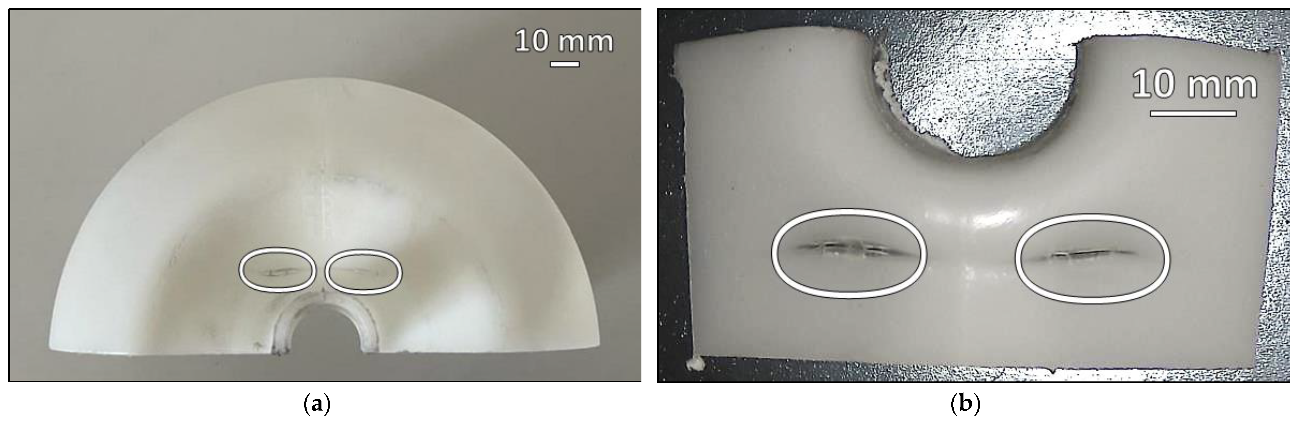
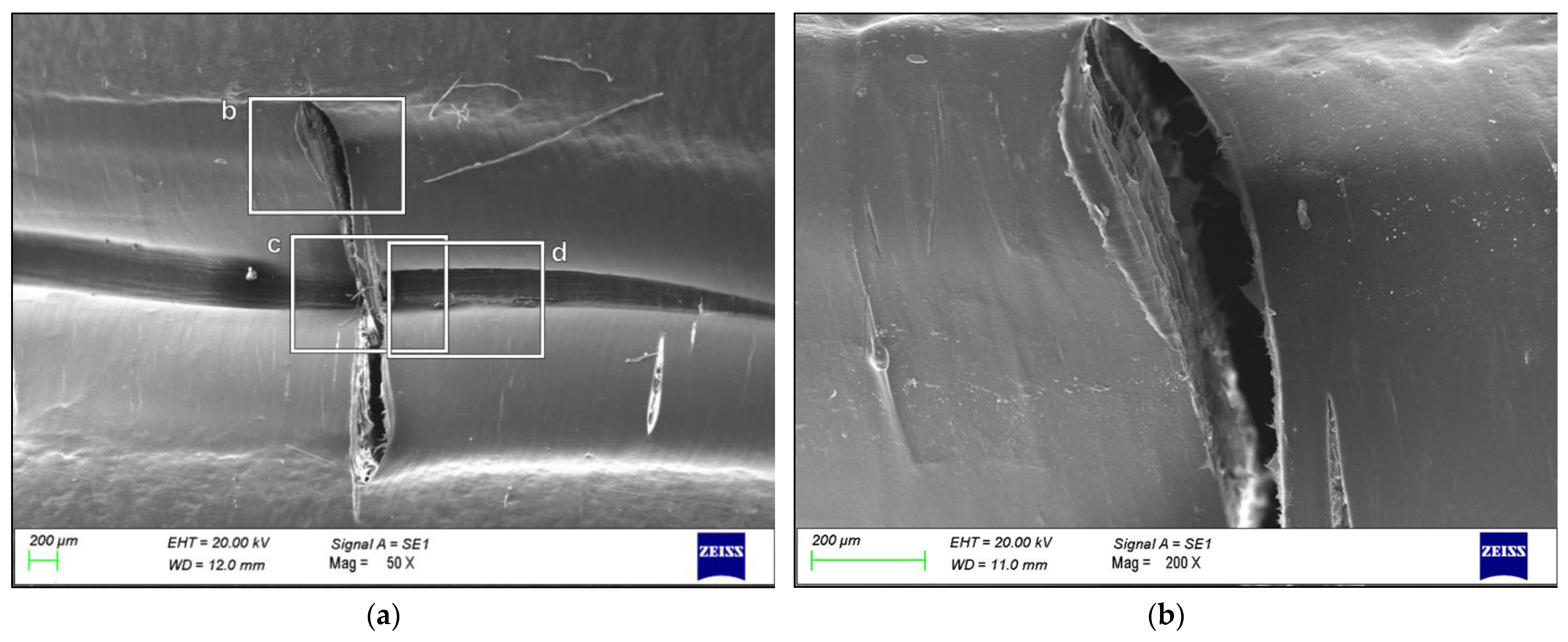
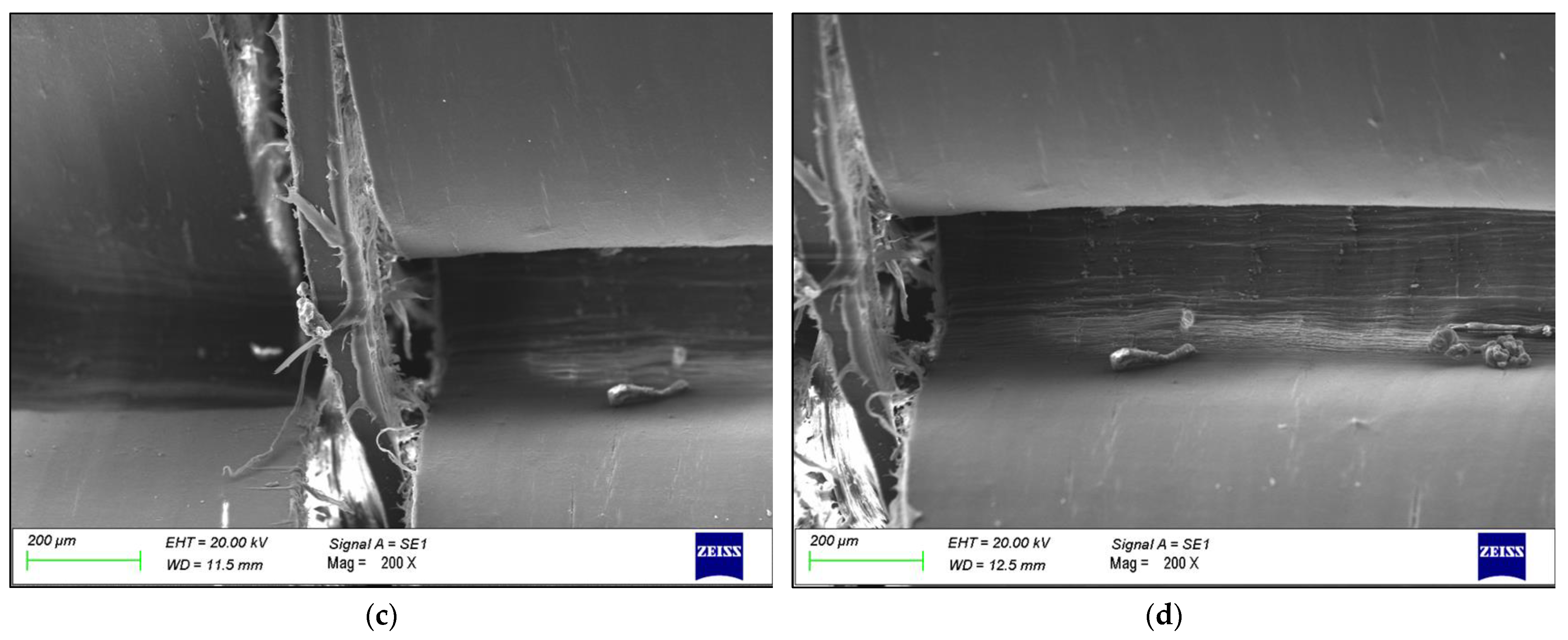
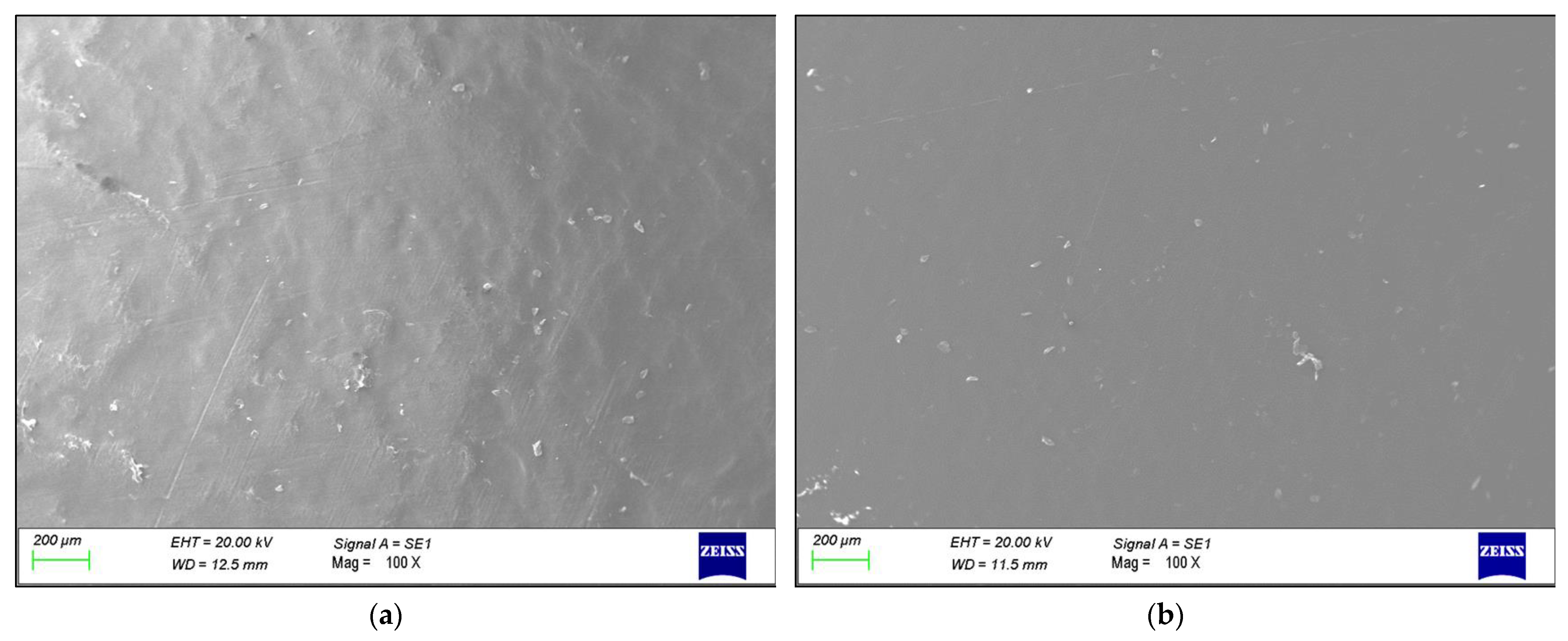
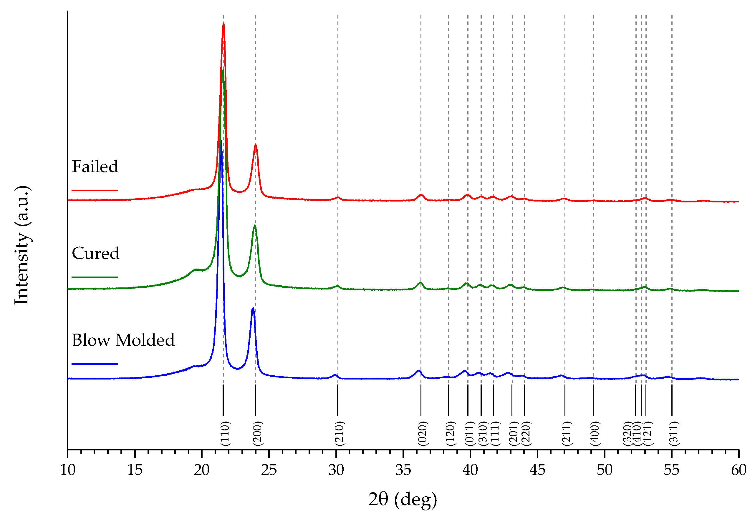
3. Results
4. Discussion
5. Conclusions
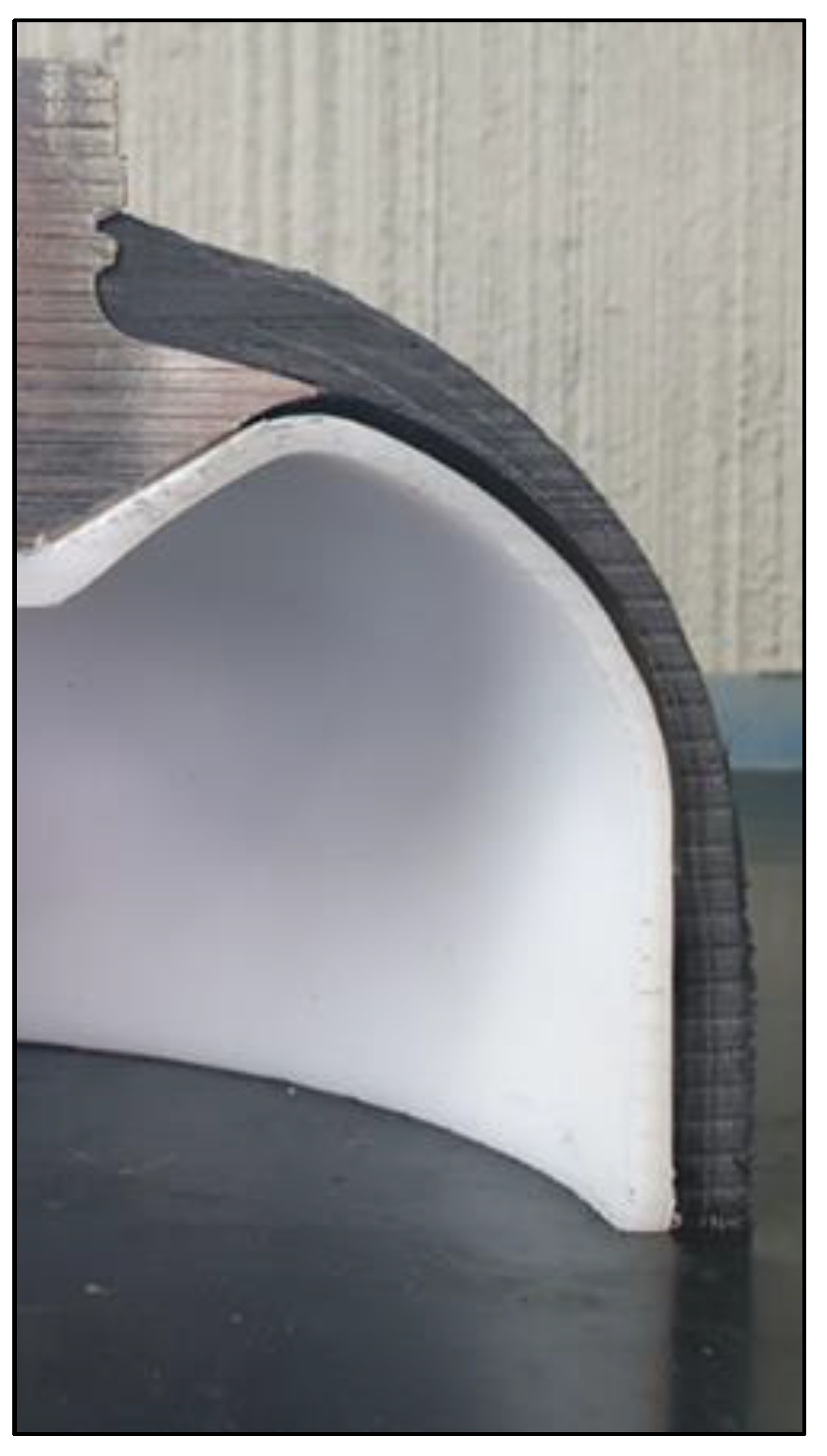
- The failure was caused by strong plastic deformation resulting in a decrease in cross-section thickness.
- Morphological and chemical analyses performed by means of SEM/EDXS, FTIR, XRD, and DSC did not show any major changes occurring during the production cycle of the liner, which could justify the creation of a trigger point for failure.
- The reason for the failure was plausibly due to a geometric issue. In a fatigue test with pressure cycles, the physical gap between liner and shell causes small deformations that can lead to the observed thickness reduction. The improvement of the interface between liner and shell, for example with the use of improved adhesives, could solve or mitigate the issue.
Supplementary Materials
Author Contributions
Funding
Institutional Review Board Statement
Data Availability Statement
Acknowledgments
Conflicts of Interest
References
- Ross, D.K. Hydrogen Storage: The Major Technological Barrier to the Development of Hydrogen Fuel Cell Cars. Vacuum 2006, 80, 1084–1089. [Google Scholar] [CrossRef]
- Zhang, M.; Lv, H.; Kang, H.; Zhou, W.; Zhang, C. A Literature Review of Failure Prediction and Analysis Methods for Composite High-Pressure Hydrogen Storage Tanks. Int. J. Hydrogen Energy 2019, 44, 25777–25799. [Google Scholar] [CrossRef]
- Sakintuna, B.; Lamaridarkrim, F.; Hirscher, M. Metal Hydride Materials for Solid Hydrogen Storage: A Review. Int. J. Hydrogen Energy 2007, 32, 1121–1140. [Google Scholar] [CrossRef]
- Capurso, G.; Schiavo, B.; Jepsen, J.; Lozano, G.A.; Metz, O.; Klassen, T.; Dornheim, M. Metal Hydride-Based Hydrogen Storage Tank Coupled with an Urban Concept Fuel Cell Vehicle: Off Board Tests. Adv. Sustain. Syst. 2018, 2, 1800004. [Google Scholar] [CrossRef]
- Hua, T.Q.; Ahluwalia, R.K.; Peng, J.-K.; Kromer, M.; Lasher, S.; McKenney, K.; Law, K.; Sinha, J. Technical Assessment of Compressed Hydrogen Storage Tank Systems for Automotive Applications. Int. J. Hydrogen Energy 2011, 36, 3037–3049. [Google Scholar] [CrossRef]
- Barthelemy, H.; Weber, M.; Barbier, F. Hydrogen Storage: Recent Improvements and Industrial Perspectives. Int. J. Hydrogen Energy 2017, 42, 7254–7262. [Google Scholar] [CrossRef]
- Sun, B.-G.; Zhang, D.-S.; Liu, F.-S. Analysis of the Cost-Effectiveness of Pressure for Vehicular High-Pressure Gaseous Hydrogen Storage Vessel. Int. J. Hydrogen Energy 2012, 37, 13088–13091. [Google Scholar] [CrossRef]
- de Miguel, N.; Acosta, B.; Moretto, P.; Ortiz Cebolla, R. Influence of the Gas Injector Configuration on the Temperature Evolution during Refueling of On-Board Hydrogen Tanks. Int. J. Hydrogen Energy 2016, 41, 19447–19454. [Google Scholar] [CrossRef]
- Adams, P.; Bengaouer, A.; Cariteau, B.; Molkov, V.; Venetsanos, A.G. Allowable Hydrogen Permeation Rate from Road Vehicles. Int. J. Hydrogen Energy 2011, 36, 2742–2749. [Google Scholar] [CrossRef]
- Yersak, T.A.; Baker, D.R.; Yanagisawa, Y.; Slavik, S.; Immel, R.; Mack-Gardner, A.; Herrmann, M.; Cai, M. Predictive Model for Depressurization-Induced Blistering of Type IV Tank Liners for Hydrogen Storage. Int. J. Hydrogen Energy 2017, 42, 28910–28917. [Google Scholar] [CrossRef]
- Durbin, D.J.; Malardier-Jugroot, C. Review of Hydrogen Storage Techniques for on Board Vehicle Applications. Int. J. Hydrogen Energy 2013, 38, 14595–14617. [Google Scholar] [CrossRef]
- Bustamante Valencia, L.; Blanc-Vannet, P.; Domergue, D.; Heudier, L.; Jamois, D. Thermal History Resulting in the Failure of Lightweight Fully-Wrapped Composite Pressure Vessel for Hydrogen in a Fire Experimental Facility. Fire Technol. 2016, 52, 421–442. [Google Scholar] [CrossRef]
- Berro Ramirez, J.P.; Halm, D.; Grandidier, J.-C.; Villalonga, S.; Nony, F. 700 Bar Type IV High Pressure Hydrogen Storage Vessel Burst–Simulation and Experimental Validation. Int. J. Hydrogen Energy 2015, 40, 13183–13192. [Google Scholar] [CrossRef]
- Magneville, B.; Gentilleau, B.; Villalonga, S.; Nony, F.; Galiano, H. Modeling, Parameters Identification and Experimental Validation of Composite Materials Behavior Law Used in 700 Bar Type IV Hydrogen High Pressure Storage Vessel. Int. J. Hydrogen Energy 2015, 40, 13193–13205. [Google Scholar] [CrossRef]
- Pépin, J.; Lainé, E.; Grandidier, J.-C.; Benoit, G.; Mellier, D.; Weber, M.; Langlois, C. Replication of Liner Collapse Phenomenon Observed in Hyperbaric Type IV Hydrogen Storage Vessel by Explosive Decompression Experiments. Int. J. Hydrogen Energy 2018, 43, 4671–4680. [Google Scholar] [CrossRef]
- Quang Dao, D.; Luche, J.; Rogaume, T.; Richard, F.; Bustamante-Valencia, L.; Ruban, S. Polyamide 6 and Polyurethane Used as Liner for Hydrogen Composite Cylinder: An Estimation of Fire Behaviours. Fire Technol. 2016, 52, 397–420. [Google Scholar] [CrossRef]
- Zheng, J.; Liu, X.; Xu, P.; Liu, P.; Zhao, Y.; Yang, J. Development of High Pressure Gaseous Hydrogen Storage Technologies. Int. J. Hydrogen Energy 2012, 37, 1048–1057. [Google Scholar] [CrossRef]
- Barboza Neto, E.S.; Chludzinski, M.; Roese, P.B.; Fonseca, J.S.O.; Amico, S.C.; Ferreira, C.A. Experimental and Numerical Analysis of a LLDPE/HDPE Liner for a Composite Pressure Vessel. Polym. Test. 2011, 30, 693–700. [Google Scholar] [CrossRef]
- Ahluwalia, R.K.; Hua, T.Q.; Peng, J.K. On-Board and Off-Board Performance of Hydrogen Storage Options for Light-Duty Vehicles. Int. J. Hydrogen Energy 2012, 37, 2891–2910. [Google Scholar] [CrossRef]
- Kis, D.I.; Kókai, E. A Review on the Factors of Liner Collapse in Type IV Hydrogen Storage Vessels. Int. J. Hydrogen Energy 2023, 50, 236–253. [Google Scholar] [CrossRef]
- Klopffer, M.H.; Flaconneche, B. Transport Properties of Gases in Polymers: Bibliographic Review. Oil Gas Sci. Technol. 2001, 56, 223–244. [Google Scholar] [CrossRef]
- Blanc-Vannet, P.; Papin, P.; Weber, M.; Renault, P.; Pepin, J.; Lainé, E.; Tantchou, G.; Castagnet, S.; Grandidier, J.-C. Sample Scale Testing Method to Prevent Collapse of Plastic Liners in Composite Pressure Vessels. Int. J. Hydrogen Energy 2019, 44, 8682–8691. [Google Scholar] [CrossRef]
- Pepin, J.; Lainé, E.; Grandidier, J.-C.; Castagnet, S.; Blanc-vannet, P.; Papin, P.; Weber, M. Determination of Key Parameters Responsible for Polymeric Liner Collapse in Hyperbaric Type IV Hydrogen Storage Vessels. Int. J. Hydrogen Energy 2018, 43, 16386–16399. [Google Scholar] [CrossRef]
- Melnichuk, M.; Gardavaud, Q.; Thiébaud, F.; Perreux, D. Numerical Assestments of Maximum Depressurisation Rate for Polymer Materials under High-Pressure Hydrogen. Int. J. Hydrogen Energy 2021, 46, 27088–27095. [Google Scholar] [CrossRef]
- Stewart, C.W. Nucleation and Growth of Bubbles in Elastomers. J. Polym. Sci. A-2 Polym. Phys. 1970, 8, 937–955. [Google Scholar] [CrossRef]
- Baudet, C.; Grandidier, J.-C.; Cangémi, L. A Damage Model for the Blistering of Polyvinylidene Fluoride Subjected to Carbon Dioxide Decompression. J. Mech. Phys. Solids 2011, 59, 1909–1926. [Google Scholar] [CrossRef]
- Bo, K.; Feng, H.; Jiang, Y.; Deng, G.; Wang, D.; Zhang, Y. Study of Blister Phenomena on Polymer Liner of Type IV Hydrogen Storage Cylinders. Int. J. Hydrogen Energy 2023, 54, 922–936. [Google Scholar] [CrossRef]
- Wang, X.; Tian, M.; Chen, X.; Xie, P.; Yang, J.; Chen, J.; Yang, W. Advances on Materials Design and Manufacture Technology of Plastic Liner of Type Ⅳ Hydrogen Storage Vessel. Int. J. Hydrogen Energy 2022, 47, 8382–8408. [Google Scholar] [CrossRef]
- Kim, M.; Lee, C.H. Hydrogenation of High-Density Polyethylene during Decompression of Pressurized Hydrogen at 90 MPa: A Molecular Perspective. Polymers 2023, 15, 2880. [Google Scholar] [CrossRef]
- Rueda, F.; Otegui, J.L.; Frontini, P. Numerical Tool to Model Collapse of Polymeric Liners in Pipelines. Eng. Fail. Anal. 2012, 20, 25–34. [Google Scholar] [CrossRef]
- Li, Y.; Li, Q.; Peng, W.; Hua, Z.; Zheng, J. A Comparative Analysis of the Regulations, Codes and Standards for on-Board High-Pressure Hydrogen Storage Cylinders. Int. J. Hydrogen Energy 2024, 54, 894–907. [Google Scholar] [CrossRef]
- ISO 11119-3:2020; Gas Cylinders Design, Construction and Testing of Refillable Composite Gas Cylinders and Tubes Part 3: Fully Wrapped Fibre Reinforced Composite Gas Cylinders and Tubes up to 450 l with Non-Load-Sharing Metallic or Non-Metallic Liners or without Liners. International Organization for Standardization: Geneva, Switzerland, 2020.
- Kuptsov, A.H.; Zhizhin, G.N. Handbook of Fourier Transform Raman and Infrared Spectra of Polymers; Physical Sciences Data; Elsevier Science & Technology: Amsterdam, The Netherlands, 1998; ISBN 9780080531946. [Google Scholar]
- Gulmine, J.V.; Janissek, P.R.; Heise, H.M.; Akcelrud, L. Polyethylene Characterization by FTIR. Polym. Test. 2002, 21, 557–563. [Google Scholar] [CrossRef]
- Caminiti, R.; Pandolfi, L.; Ballirano, P. Structure of Polyethylene from Xray Powder Diffraction: Influence of the Amorphous Fraction on Data Analysis. J. Macromol. Sci. B 2000, 39, 481–492. [Google Scholar] [CrossRef]
- Oluwoye, I.; Altarawneh, M.; Gore, J.; Dlugogorski, B.Z. Oxidation of crystalline polyethylene. Combust. Flame 2015, 162, 3681–3690. [Google Scholar] [CrossRef]
- Rizzo, P.; Baione, F.; Guerra, G.; Martinotto, L.; Albizzati, E. Polyethylene Unit Cell and Crystallinity Variations as a Consequence of Different Cross-Linking Processes. Macromolecules 2001, 34, 5175–5179. [Google Scholar] [CrossRef]
- Tarani, E.; Arvanitidis, I.; Christofilos, D.; Bikiaris, D.N.; Chrissafis, K.; Vourlias, G. Calculation of the degree of crystallinity of HDPE/GNPs nanocomposites by using various experimental techniques: A comparative study. J. Mater. Sci. 2023, 58, 1621–1639. [Google Scholar] [CrossRef]
- Motaharinejad, V.; Delnaud, L.; Fouque, M.; Lucas, A.; Shirinbayan, M.; Fitoussi, J.; Tcharkhtchi, A. Enhancement of Adhesion between the Polymeric Liner and the Metallic Connector of High-Pressure Hydrogen Storage Tank. Int. J. Mater. Form. 2021, 14, 249–260. [Google Scholar] [CrossRef]
- Guseva, M.A.; Gerasin, V.A.; Garishin, O.K.; Shadrin, V.V.; Plekhov, O.A.; Pawlak, A. Thermal Effects under Elastic and Plastic Deformation of Polyethylene. Polymer 2015, 56, 416–427. [Google Scholar] [CrossRef]
- Pawlak, A.; Galeski, A.; Rozanski, A. Cavitation during Deformation of Semicrystalline Polymers. Prog. Polym. Sci. 2014, 39, 921–958. [Google Scholar] [CrossRef]


| Sample | % C | % O |
|---|---|---|
| Blow Molded | 96.64 ± 0.47 | 3.36 ± 0.47 |
| Cured | 97.58 ± 1.20 | 2.42 ± 1.20 |
| Failed | 93.89 ± 1.06 | 6.11 ± 1.06 |
| Bands | Wavenumber (cm−1) | Assignment |
|---|---|---|
| 1 | 2919 | CH2 asymmetric stretching |
| 2 | 2851 | CH2 asymmetric stretching |
| 3 | 1473 and 1463 | Bending deformation |
| 4 | 731 and 720 | Rocking deformation |
| 5 | 1741 | C=O |
| 6 | 1711 | C=O |
| Sample | Melting Enthalpy (J g−1) | Crystallinity (%) | T onset (°C) | T peak (°C) |
|---|---|---|---|---|
| Blow Molded | 166.417 ± 4.853 | 56.798 ± 1.656 | 123.653 ± 0.294 | 136.500 ± 2.548 |
| Cured | 160.317 ± 3.211 | 54.716 ± 1.096 | 123.550 ± 0.918 | 134.340 ± 1.011 |
| Failed | 169.600 ± 0.269 | 57.884 ± 0.092 | 123.270 ± 0.679 | 132.840 ± 0.552 |
Disclaimer/Publisher’s Note: The statements, opinions and data contained in all publications are solely those of the individual author(s) and contributor(s) and not of MDPI and/or the editor(s). MDPI and/or the editor(s) disclaim responsibility for any injury to people or property resulting from any ideas, methods, instructions or products referred to in the content. |
© 2024 by the authors. Licensee MDPI, Basel, Switzerland. This article is an open access article distributed under the terms and conditions of the Creative Commons Attribution (CC BY) license (https://creativecommons.org/licenses/by/4.0/).
Share and Cite
Rondinella, A.; Capurso, G.; Zanocco, M.; Basso, F.; Calligaro, C.; Menotti, D.; Agnoletti, A.; Fedrizzi, L. Study of the Failure Mechanism of a High-Density Polyethylene Liner in a Type IV High-Pressure Storage Tank. Polymers 2024, 16, 779. https://doi.org/10.3390/polym16060779
Rondinella A, Capurso G, Zanocco M, Basso F, Calligaro C, Menotti D, Agnoletti A, Fedrizzi L. Study of the Failure Mechanism of a High-Density Polyethylene Liner in a Type IV High-Pressure Storage Tank. Polymers. 2024; 16(6):779. https://doi.org/10.3390/polym16060779
Chicago/Turabian StyleRondinella, Alfredo, Giovanni Capurso, Matteo Zanocco, Federico Basso, Chiara Calligaro, Davide Menotti, Alberto Agnoletti, and Lorenzo Fedrizzi. 2024. "Study of the Failure Mechanism of a High-Density Polyethylene Liner in a Type IV High-Pressure Storage Tank" Polymers 16, no. 6: 779. https://doi.org/10.3390/polym16060779