

Enhancing the Cooling Efficiency of Aluminum-Filled Epoxy Resin Rapid Tool by Changing Inner Surface Roughness of Cooling Channels

 ,
,
Abstract
:1. Introduction
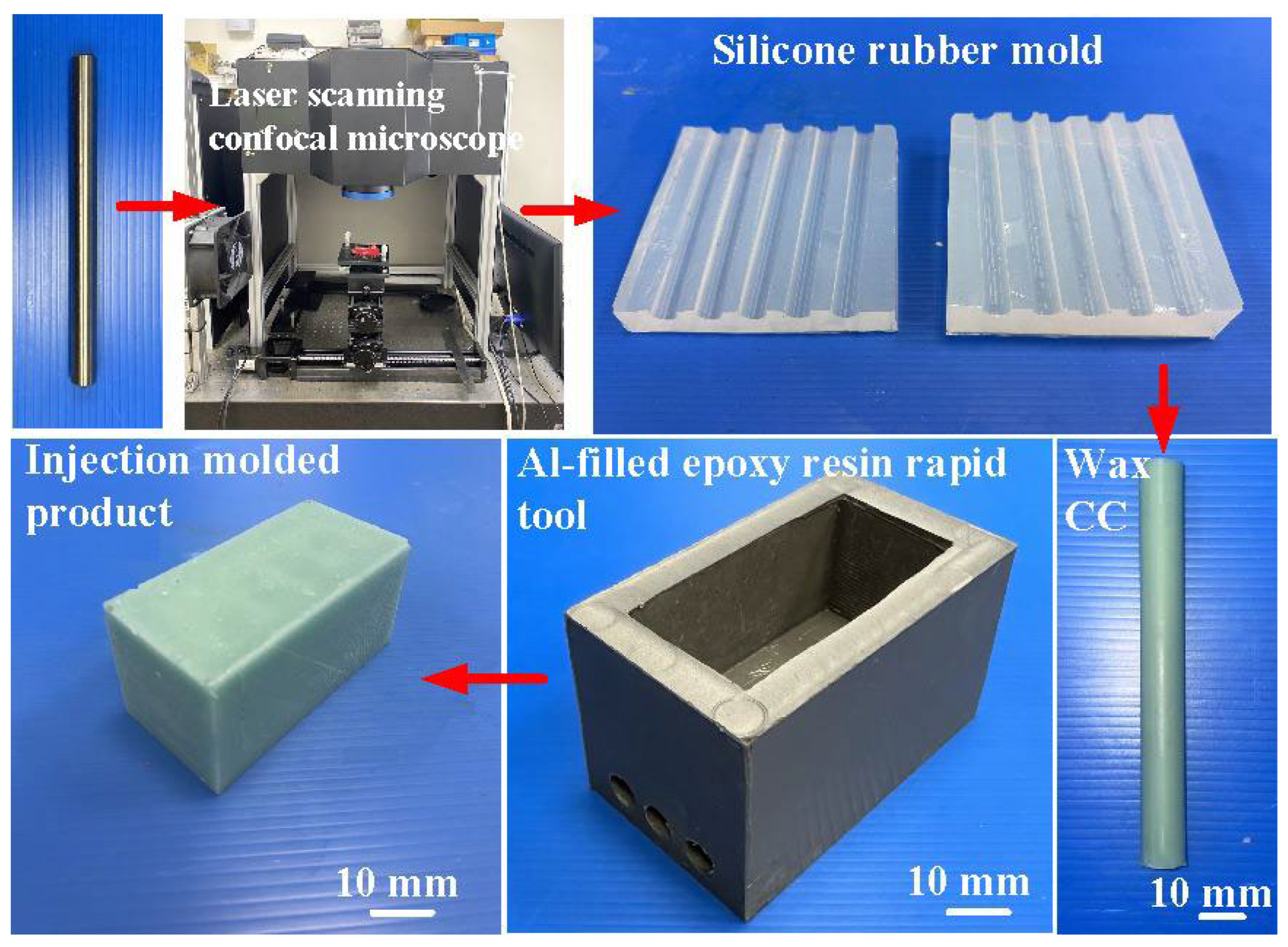
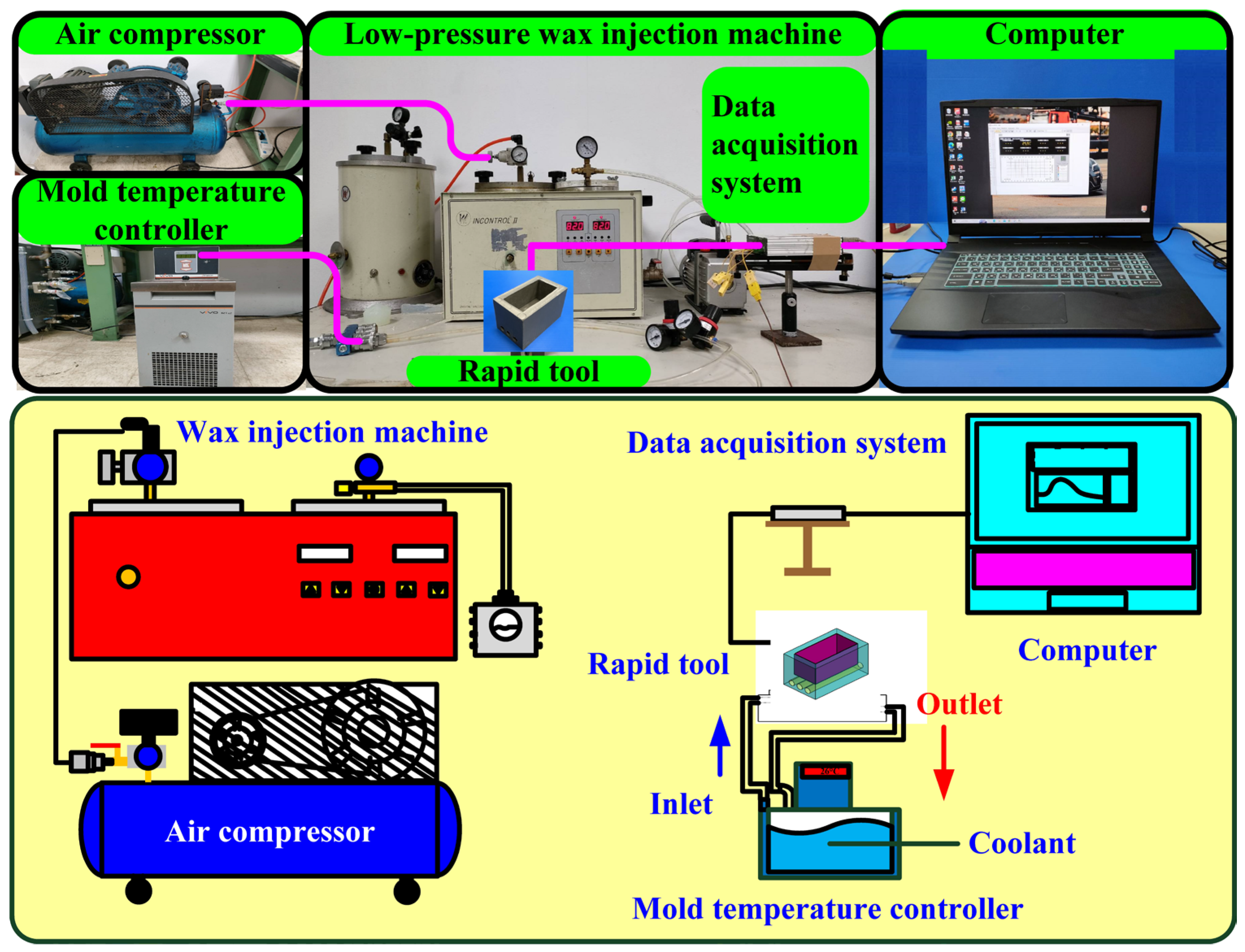
2. Experiment
3. Results and Discussion
4. Conclusions
- The results of this study underscore the substantial potential applications within the investment casting industry, particularly attributed to the noteworthy effects of decreased cooling times on production costs during the mass manufacturing of wax patterns.
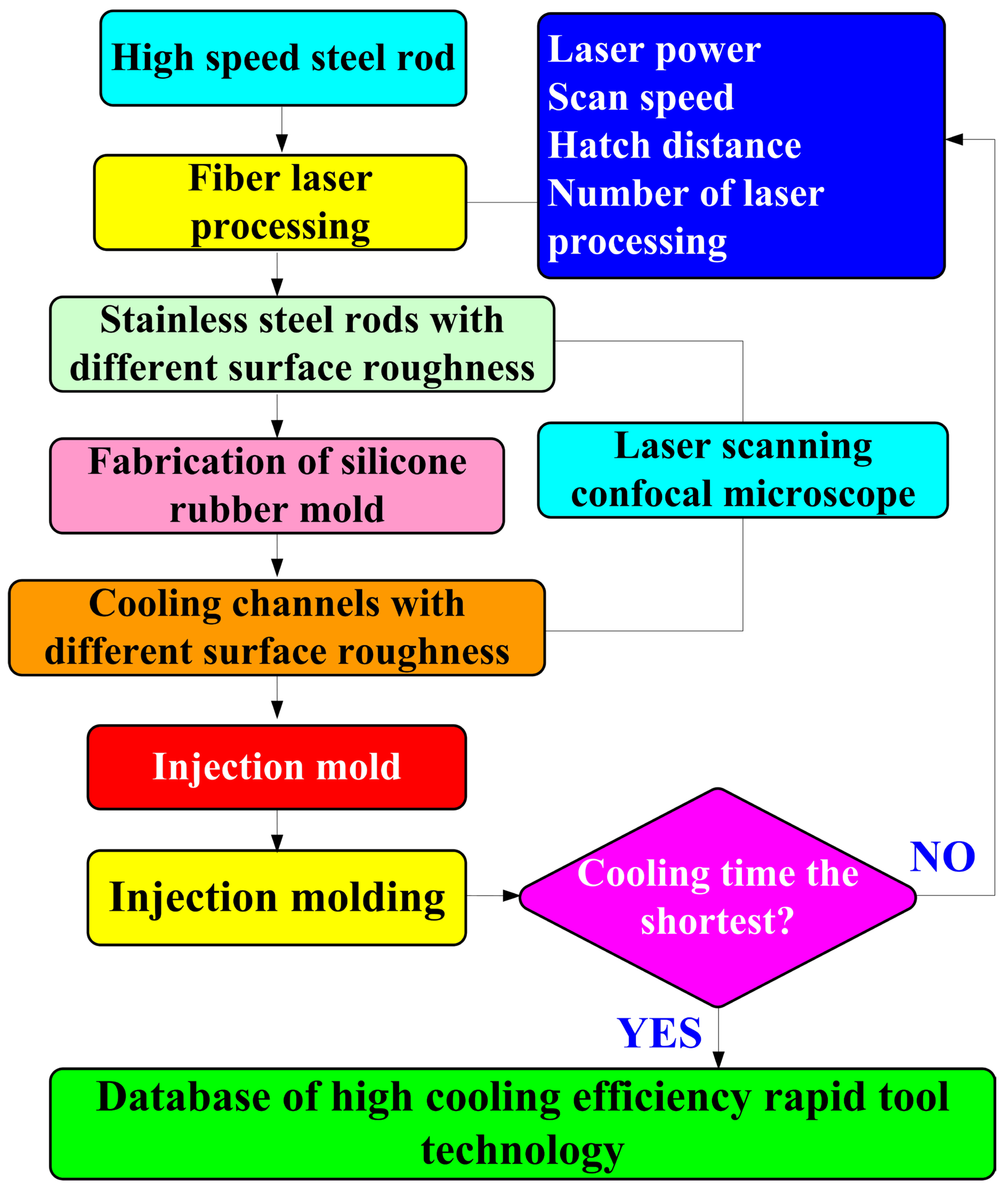
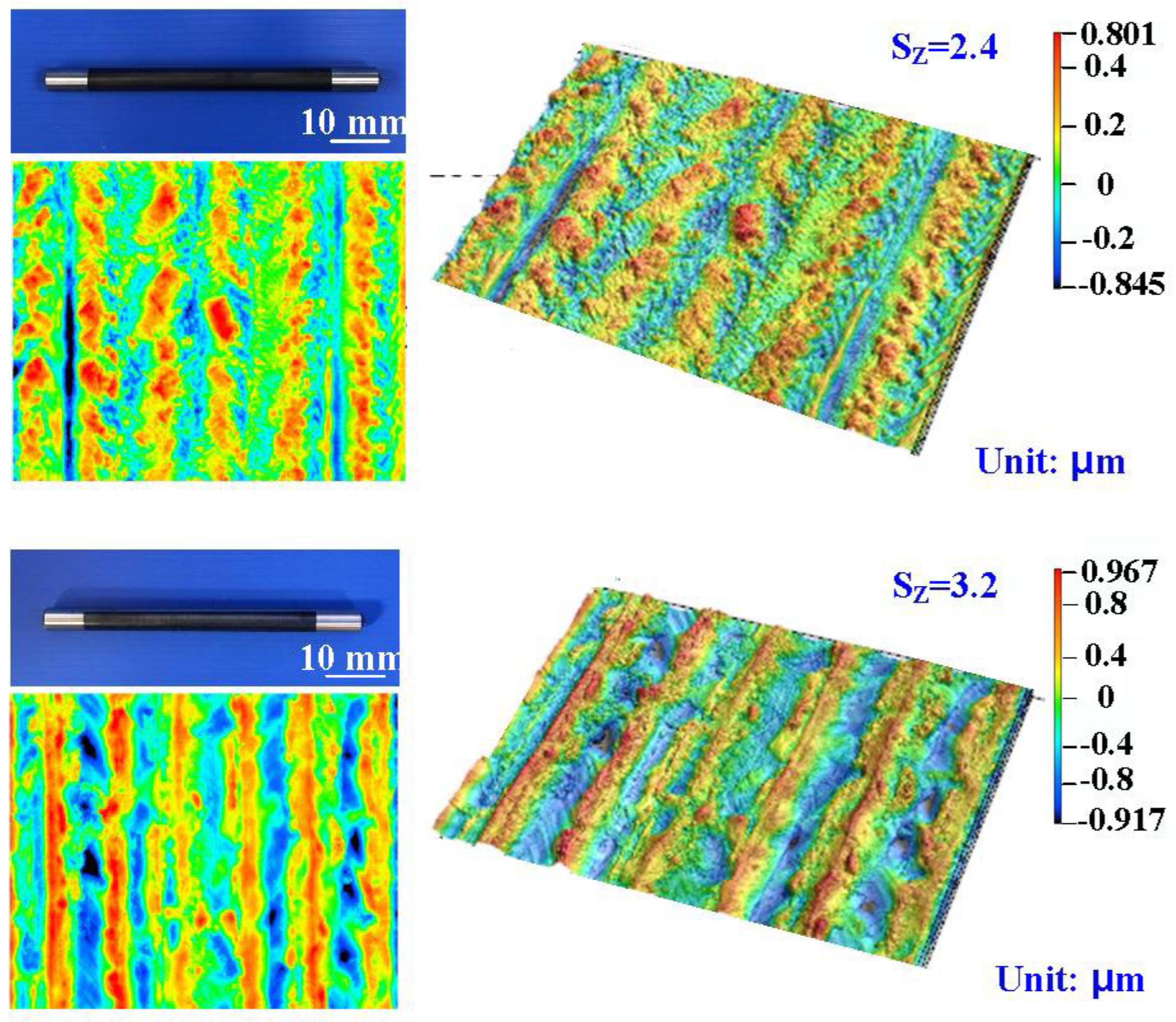
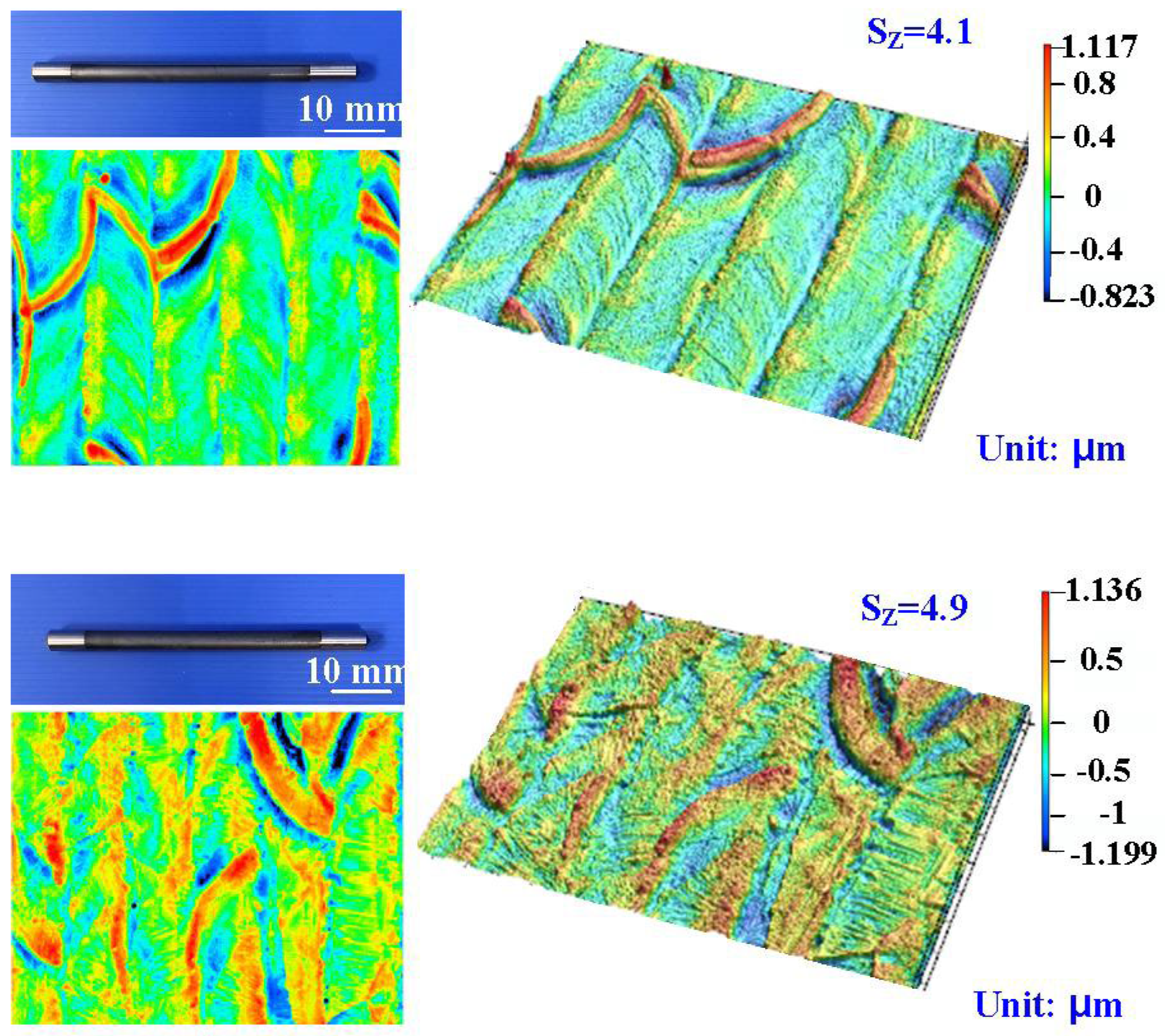
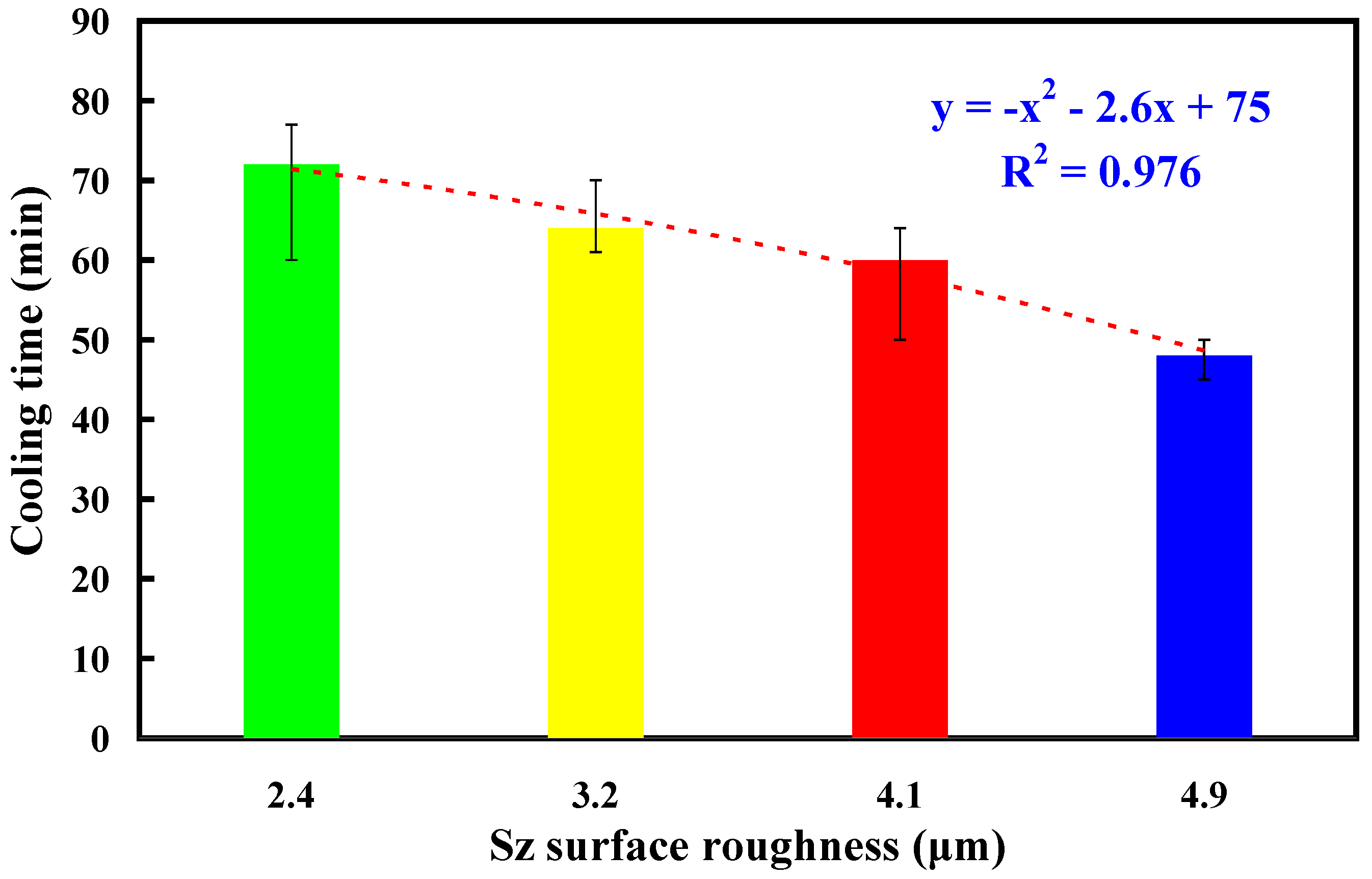
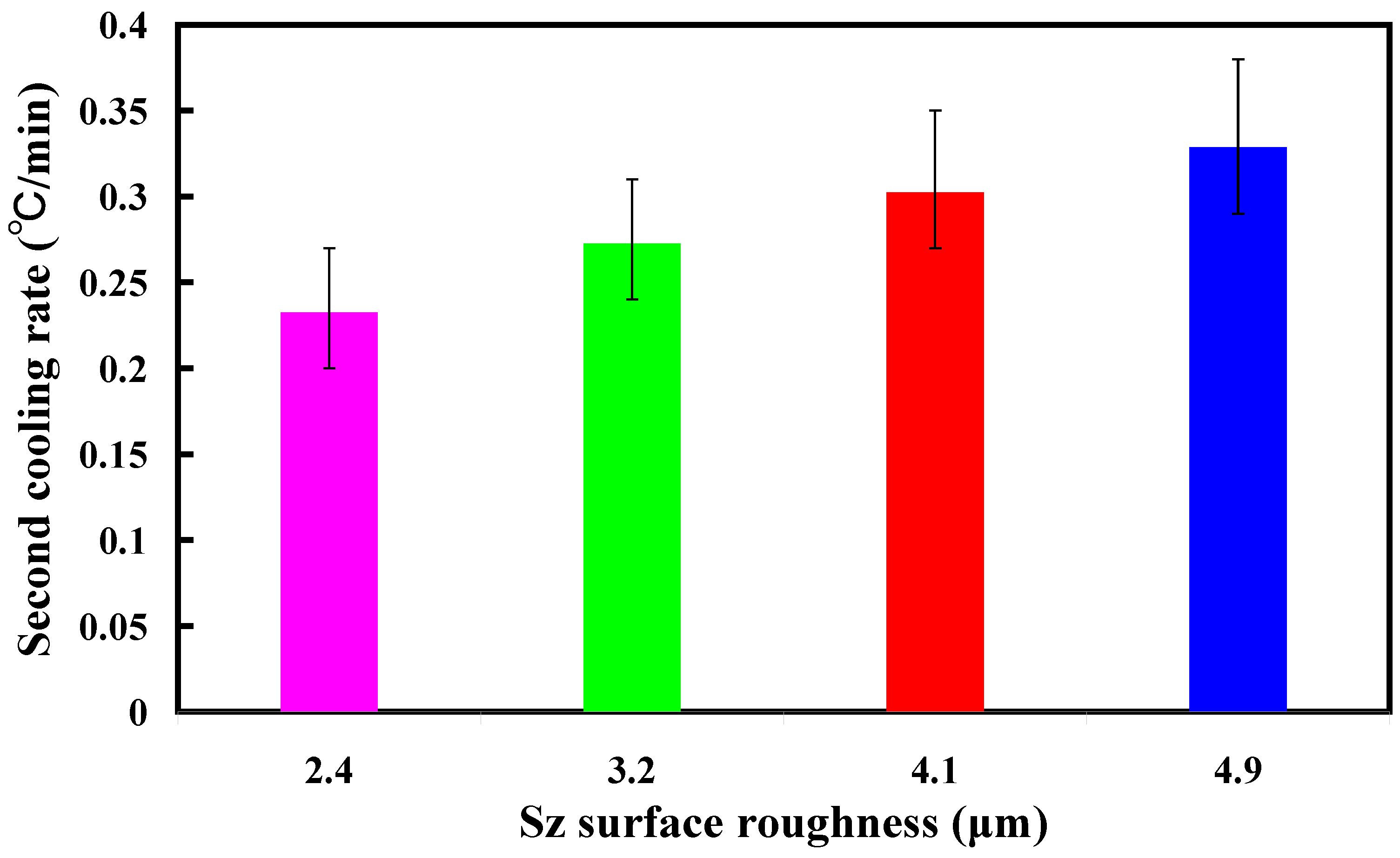
- The results showed that the application of fiber laser processing on the surface of high-speed steel rods allows for the development of microstructures with diverse surface roughness. The average cooling time for the injection-molded products (y) can be determined by the Sz surface roughness (x) according to the prediction equation of y = −x2 − 2.6x + 75 with a correlation coefficient of 0.976.
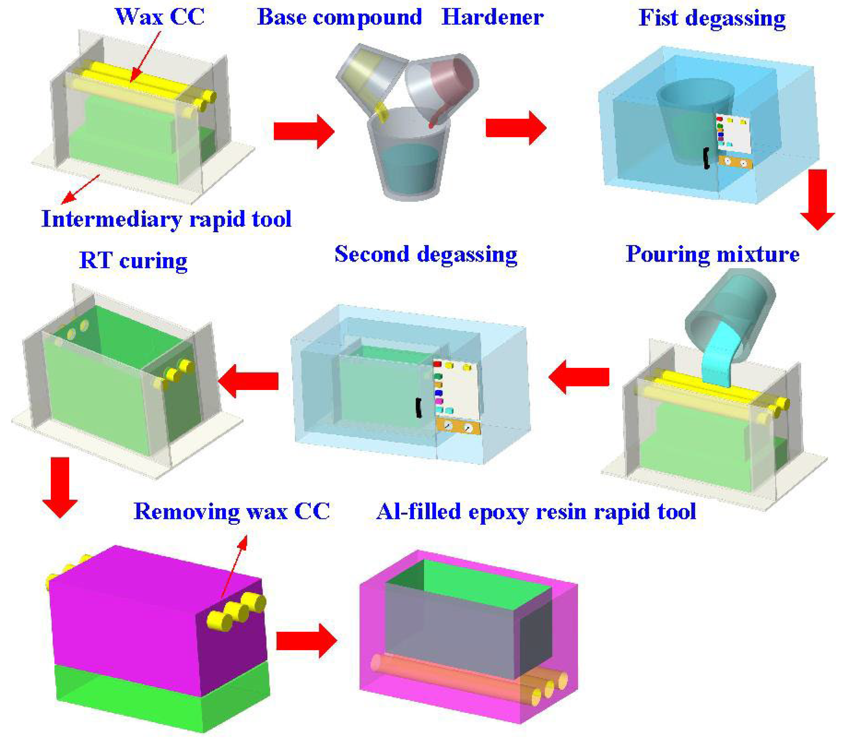
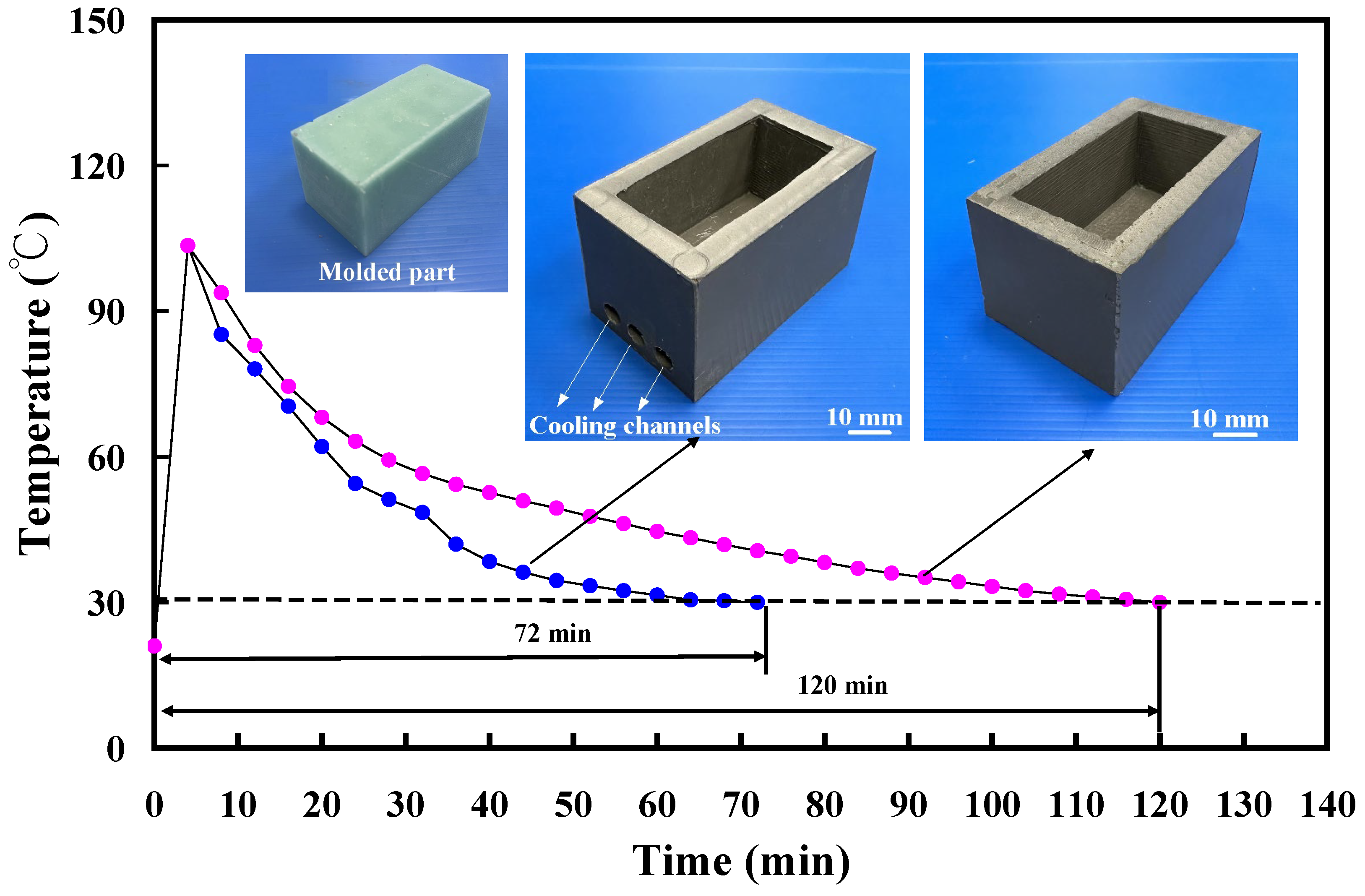
- The surface roughness of the inner walls of the cooling channel significantly impacts the cooling duration of injection-molded items. In contrast to low-pressure wax injection molding using an aluminum-filled epoxy resin rapid tool with a surface roughness of 2.4 μm on the cooling channel’s inner walls, employing an aluminum-filled epoxy resin rapid tool with a surface roughness of 4.9 μm for low-pressure wax injection molding can result in time savings and an improvement in cooling efficiency of approximately 34%.
- The utilization of an aluminum-filled epoxy resin rapid tool with a surface roughness of 4.9 μm on the inner walls of the cooling channel can reduce cooling time up to approximately 60% compared to low-pressure wax injection molding using an aluminum-filled epoxy resin rapid tool without a cooling channel.
Author Contributions
Funding
Institutional Review Board Statement
Data Availability Statement
Conflicts of Interest
References
- Arman, S.; Lazoglu, I. A comprehensive review of injection mold cooling by using conformal cooling channels and thermally enhanced molds. Int. J. Adv. Manuf. Technol. 2023, 127, 2035–2106. [Google Scholar] [CrossRef]
- Marl, S.; Giesen, R.-U.; Heim, H.-P. Liquid Silicone Rubber Foamed with Thermoplastic Expandable Microspheres. Materials 2022, 15, 3779. [Google Scholar] [CrossRef]
- Nabavi, S.F.; Farshidianfar, A.; Dalir, H. An applicable review on recent laser beam cutting process characteristics modeling: Geometrical, metallurgical, mechanical, and defect. Int. J. Adv. Manuf. Technol. 2023, 130, 2159–2217. [Google Scholar] [CrossRef]
- Rodríguez, N.B.; Moroni, F.; Lutey, A.H.A.; Favi, C. Sustainable design and life cycle engineering of adhesive joints for polymeric products: Assessment of surface activation technologies. Int. J. Adv. Manuf. Technol. 2023, 130, 1279–1306. [Google Scholar] [CrossRef]
- Bian, Y.; Dong, B.; Chen, B.; Guo, J.; Li, S.; Tian, C.; Xu, S.; He, X.; Yu, G. Dynamic evolution behavior of cracks for single-track and multi-track clads in laser cladding. Int. J. Adv. Manuf. Technol. 2023, 130, 2313–2328. [Google Scholar] [CrossRef]
- Piekło, J.; Garbacz-Klempka, A. Analysis of Phenomenon of Plasticity Loss of Steel Core Made by Selective Laser Melting Method in Zone of Pressure Mould Conformal Cooling Channel. Materials 2023, 16, 4205. [Google Scholar] [CrossRef]
- Nguyen, V.-T.; Minh, P.S.; Uyen, T.M.T.; Do, T.T.; Ha, N.C.; Nguyen, V.T.T. Conformal Cooling Channel Design for Improving Temperature Distribution on the Cavity Surface in the Injection Molding Process. Polymers 2023, 15, 2793. [Google Scholar] [CrossRef] [PubMed]
- Vargas-Isaza, C.; Benitez-Lozano, A.; Rodriguez, J. Evaluating the Cooling Efficiency of Polymer Injection Molds by Computer Simulation Using Conformal Channels. Polymers 2023, 15, 4044. [Google Scholar] [CrossRef]
- Minh, P.S.; Dang, H.-S.; Ha, N.C. Optimization of 3D Cooling Channels in Plastic Injection Molds by Taguchi-Integrated Principal Component Analysis (PCA). Polymers 2023, 15, 1080. [Google Scholar] [CrossRef]
- Choi, J.H.; Gim, J.; Rhee, B. A Novel Design Method of an Evolutionary Mold Cooling Channel Using Biomimetic Engineering. Polymers 2023, 15, 798. [Google Scholar] [CrossRef] [PubMed]
- Torres-Alba, A.; Mercado-Colmenero, J.M.; Caballero-Garcia, J.d.D.; Martin-Doñate, C. Application of New Conformal Cooling Layouts to the Green Injection Molding of Complex Slender Polymeric Parts with High Dimensional Specifications. Polymers 2023, 15, 558. [Google Scholar] [CrossRef]
- Gotlih, J.; Brezocnik, M.; Pal, S.; Drstvensek, I.; Karner, T.; Brajlih, T. A Holistic Approach to Cooling System Selection and Injection Molding Process Optimization Based on Non-Dominated Sorting. Polymers 2022, 14, 4842. [Google Scholar] [CrossRef]
- Kanbur, B.B.; Zhou, Y.; Shen, S.; Wong, K.H.; Chen, C.; Shocket, A.; Duan, F. Metal Additive Manufacturing of Plastic Injection Molds with Conformal Cooling Channels. Polymers 2022, 14, 424. [Google Scholar] [CrossRef]
- Torres-Alba, A.; Mercado-Colmenero, J.M.; Caballero-Garcia, J.d.D.; Martin-Doñate, C. Application of New Triple Hook-Shaped Conformal Cooling Channels for Cores and Sliders in Injection Molding to Reduce Residual Stress and Warping in Complex Plastic Optical Parts. Polymers 2021, 13, 2944. [Google Scholar] [CrossRef]
- Torres-Alba, A.; Mercado-Colmenero, J.M.; Caballero-Garcia, J.D.D.; Martin-Doñate, C. A Hybrid Cooling Model Based on the Use of Newly Designed Fluted Conformal Cooling Channels and Fastcool Inserts for Green Molds. Polymers 2021, 13, 3115. [Google Scholar] [CrossRef]
- Abbès, B.; Abbès, F.; Abdessalam, H.; Upganlawar, A. Finite element cooling simulations of conformal cooling hybrid injection molding tools manufactured by selective laser melting. Int. J. Adv. Manuf. Technol. 2019, 103, 2515–2522. [Google Scholar] [CrossRef]
- Hunter, L.W.; Brackett, D.; Brierley, N.; Yang, J.; Attallah, M.M. Assessment of trapped powder removal and inspection strategies for powder bed fusion techniques. Int. J. Adv. Manuf. Technol. 2020, 106, 4521–4532. [Google Scholar] [CrossRef]
- Mercado-Colmenero, J.M.; Martin-Doñate, C.; Rodriguez-Santiago, M.; Moral-Pulido, F.; Rubio-Paramio, M.A. A new conformal cooling lattice design procedure for injection molding applications based on expert algorithms. Int. J. Adv. Manuf. Technol. 2019, 102, 1719–1746. [Google Scholar] [CrossRef]
- Li, Z.; Wang, X.; Gu, J.; Ruan, S.; Shen, C.; Lyu, Y.; Zhao, Y. Topology Optimization for the Design of Conformal Cooling System in Thin-wall Injection Molding Based on BEM. Int. J. Adv. Manuf. Technol. 2018, 94, 1041–1059. [Google Scholar] [CrossRef]
- Shin, K.-H. A method for representation and analysis of conformal cooling channels in molds made of functionally graded tool steel/Cu materials. J. Mech. Sci. Technol. 2019, 33, 1743–1750. [Google Scholar] [CrossRef]
- Park, H.-S.; Dang, X.-P. Optimization of conformal cooling channels with array of baffles for plastic injection mold. Int. J. Precis. Eng. Manuf. 2010, 11, 879–890. [Google Scholar] [CrossRef]
- Yuan, X.; Tao, Z.; Li, H.; Tian, Y. Experimental investigation of surface roughness effects on flow behavior and heat transfer characteristics for circular microchannels. Chin. J. Aeronaut. 2016, 29, 1575–1581. [Google Scholar] [CrossRef]
- Peng, M.; Chen, L.; Ji, W.; Tao, W. Numerical study on flow and heat transfer in a multi-jet microchannel heat sink. Int. J. Heat Mass Transf. 2020, 157, 119982. [Google Scholar] [CrossRef]
- Kuo, C.-C.; Jiang, Z.-F.; Lee, J.-H. Effects of cooling time of molded parts on rapid injection molds with different layouts and surface roughness of conformal cooling channels. Int. J. Adv. Manuf. Technol. 2019, 103, 2169–2182. [Google Scholar] [CrossRef]
- Kuntoğlu, M.; Salur, E.; Canli, E.; Aslan, A.; Gupta, M.K.; Waqar, S.; Krolczyk, G.M.; Xu, J. A state of the art on surface morphology of selective laser-melted metallic alloys. Int. J. Adv. Manuf. Technol. 2023, 127, 1103–1142. [Google Scholar] [CrossRef]
- Kuo, C.-C.; Tasi, Q.-Z.; Huang, S.-H.; Tseng, S.-F. Enhancing Surface Temperature Uniformity in a Liquid Silicone Rubber Injection Mold with Conformal Heating Channels. Materials 2023, 16, 5739. [Google Scholar] [CrossRef]
- Jia, J.; Ma, L.; Sun, Y.; Li, D.; Liu, W.; Han, Z.; Li, M. Study on the surface formation mechanism and theoretical model of brittle surface roughness in turning machinable ceramics. Int. J. Adv. Manuf. Technol. 2024, 130, 3877–3889. [Google Scholar] [CrossRef]
- Zeng, S.; Pi, D.; Xu, T. Milling surface roughness prediction method based on spatiotemporal ensemble learning. Int. J. Adv. Manuf. Technol. 2023, 128, 91–119. [Google Scholar] [CrossRef]
- Ouazzani, K.; El Jai, M.; Akhrif, I.; Radouani, M.; El Fahime, B. An experimental study of FDM parameter effects on ABS surface quality: Roughness analysis. Int. J. Adv. Manuf. Technol. 2023, 127, 151–178. [Google Scholar] [CrossRef]
- Koç, E.; Zeybek, S.; Kısasöz, B.; Çalışkan, C.I.; Bulduk, M.E. Estimation of surface roughness in selective laser sintering using computational models. Int. J. Adv. Manuf. Technol. 2022, 123, 3033–3045. [Google Scholar] [CrossRef]
- Yang, J.S.; Jeong, M.; Park, Y.G.; Ha, M.Y. Numerical study on the flow and heat transfer characteristics in a dimple cooling channel with a wedge-shaped vortex generator. Int. J. Heat Mass Transf. 2019, 136, 1064–1078. [Google Scholar] [CrossRef]
- Burlaga, B.; Kroma, A.; Poszwa, P.; Kłosowiak, R.; Popielarski, P.; Stręk, T. Heat Transfer Analysis of 3D Printed Wax Injection Mold Used in Investment Casting. Materials 2022, 15, 6545. [Google Scholar] [CrossRef] [PubMed]
- Addugala, H.; Venugopal, V.N.; Rengasamy, S.; Yadalam, P.K.; Albar, N.H.; Alamoudi, A.; Bahammam, S.A.; Zidane, B.; Bahammam, H.A.; Bhandi, S.; et al. Marginal and Internal Gap of Metal Copings Fabricated Using Three Types of Resin Patterns with Subtractive and Additive Technology: An In Vitro Comparison. Materials 2022, 15, 6397. [Google Scholar] [CrossRef] [PubMed]
- Narwani, S.; Yadav, N.S.; Hazari, P.; Saxena, V.; Alzahrani, A.H.; Alamoudi, A.; Zidane, B.; Albar, N.H.M.; Robaian, A.; Kishnani, S.; et al. Comparison of Tensile Bond Strength of Fixed-Fixed Versus Cantilever Single- and Double-Abutted Resin-Bonded Bridges Dental Prosthesis. Materials 2022, 15, 5744. [Google Scholar] [CrossRef] [PubMed]
- Alshehri, H.A.; Altaweel, S.M.; Alshaibani, R.; Alahmari, E.A.; Alotaibi, H.N.; Alfouzan, A.F.; Labban, N. Effect of Different Wax Pattern Manufacturing Techniques on the Marginal Fit of Lithium Disilicate Crowns. Materials 2022, 15, 4774. [Google Scholar] [CrossRef] [PubMed]
- Zamani, P.; Zabihi, O.; Ahmadi, M.; Zamani, M.R.; Zohuriaan-Mehr, M.J.; Kannangara, T.; Joseph, P.; Naebe, M. Assessing sustainability and green chemistry in synthesis of a vanillin-based vitrimer at scale: Enabling sustainable manufacturing of recyclable carbon fiber composites. Compos. Part A Appl. Sci. Manuf. 2024, 179, 108016. [Google Scholar] [CrossRef]
- Dasari, S.S.; Wright, A.J.; Carroll, J.M.; Sarmah, A.; Carey, D.G.; Nagabandi, N.; Tran, T.Q.; Green, M.J. Freeform additive manufacturing of carbon fiber reinforced composites using dielectric barrier discharge-assisted Joule heating. Compos. Part A Appl. Sci. Manuf. 2024, 179, 108047. [Google Scholar] [CrossRef]
- Alexander Air, B. Gangadhara Prusty, Manufacturing feasibility of a bend free ellipsoidal composite pressure vessel using automated fibre placement. Compos. Part A Appl. Sci. Manuf. 2024, 177, 107968. [Google Scholar]
- Mao, M.; Liu, S.; Jiang, J.; Sun, S.; Wang, D. Study on flow field and convective heat transfer characteristics in grinding zone of large spiral angle flow disturbance grooved wheel. Int. J. Adv. Manuf. Technol. 2023, 129, 39–63. [Google Scholar] [CrossRef]
- Tian, S.; Xie, X.; Xu, W.; Liu, J.; Zhang, X. Dynamic assessment of sustainable manufacturing capability based on correlation relationship for industrial cloud robotics. Int. J. Adv. Manuf. Technol. 2023, 124, 3113–3135. [Google Scholar] [CrossRef]
- Chai, M.; Li, Z.; Yan, H.; Huang, Z. Flow field characteristics analysis of interelectrode gap in electrochemical machining of film cooling holes. Int. J. Adv. Manuf. Technol. 2021, 112, 525–536. [Google Scholar] [CrossRef]
- Da Silva, L.J.; Souza, D.M.; de Araújo, D.B.; Reis, R.P.; Scotti, A. Concept and validation of an active cooling technique to mitigate heat accumulation in WAAM. Int. J. Adv. Manuf. Technol. 2020, 107, 2513–2523. [Google Scholar] [CrossRef]
- Abdelrazek, A.H.; Choudhury, I.A.; Nukman, Y.; Kazi, S.N. Metal cutting lubricants and cutting tools: A review on the performance improvement and sustainability assessment. Int. J. Adv. Manuf. Technol. 2020, 106, 4221–4245. [Google Scholar] [CrossRef]
- Ricciardi, M.R.; Papa, I.; Coppola, G.; Lopresto, V.; Sansone, L.; Antonucci, V. Effect of Plasma Treatment on the Impact Behavior of Epoxy/Basalt Fiber-Reinforced Composites: A Preliminary Study. Polymers 2021, 13, 1293. [Google Scholar] [CrossRef]
- Khettabi, I.; Benyoucef, L.; Boutiche, M.A. Sustainable reconfigurable manufacturing system design using adapted multi-objective evolutionary-based approaches. Int. J. Adv. Manuf. Technol. 2021, 115, 3741–3759. [Google Scholar] [CrossRef]


| Parameter | Value |
|---|---|
| Spot diameter (μm) | 40 |
| Maximum average power (W) | 30 |
| Wavelength (nm) | 1064 |
| Pulse duration (ns) | 4 |
| Focal length (mm) | 125 |
| Maximum pulse repetition rate (MHz) | 1 |
| Processing laser power (W) | 28 |
| Hatch distance (mm) | 0.05 |
| Number of laser processing | 1, 3, 5, 7 |
Disclaimer/Publisher’s Note: The statements, opinions and data contained in all publications are solely those of the individual author(s) and contributor(s) and not of MDPI and/or the editor(s). MDPI and/or the editor(s) disclaim responsibility for any injury to people or property resulting from any ideas, methods, instructions or products referred to in the content. |
© 2024 by the authors. Licensee MDPI, Basel, Switzerland. This article is an open access article distributed under the terms and conditions of the Creative Commons Attribution (CC BY) license (https://creativecommons.org/licenses/by/4.0/).
Share and Cite
Kuo, C.-C.; Chen, H.-W.; Lin, G.-F.; Huang, S.-H.; Tseng, S.-F. Enhancing the Cooling Efficiency of Aluminum-Filled Epoxy Resin Rapid Tool by Changing Inner Surface Roughness of Cooling Channels. Polymers 2024, 16, 874. https://doi.org/10.3390/polym16070874
Kuo C-C, Chen H-W, Lin G-F, Huang S-H, Tseng S-F. Enhancing the Cooling Efficiency of Aluminum-Filled Epoxy Resin Rapid Tool by Changing Inner Surface Roughness of Cooling Channels. Polymers. 2024; 16(7):874. https://doi.org/10.3390/polym16070874
Chicago/Turabian StyleKuo, Chil-Chyuan, Hong-Wei Chen, Geng-Feng Lin, Song-Hua Huang, and Shih-Feng Tseng. 2024. "Enhancing the Cooling Efficiency of Aluminum-Filled Epoxy Resin Rapid Tool by Changing Inner Surface Roughness of Cooling Channels" Polymers 16, no. 7: 874. https://doi.org/10.3390/polym16070874