The Pseudo-Bilayer Bulk Heterojunction Active Layer of Polymer Solar Cells in Green Solvent with 18.48% Efficiency

Abstract
:1. Introduction
2. Materials and Methods
3. Results and Discussion
4. Conclusions
Supplementary Materials
Author Contributions
Funding
Data Availability Statement
Conflicts of Interest
References
- Fu, J.; Yang, Q.; Huang, P.; Chung, S.; Cho, K.; Kan, Z.; Liu, H.; Lu, X.; Lang, Y.; Lai, H. Rational molecular and device design enables organic solar cells approaching 20% efficiency. Nat. Commun. 2024, 15, 1830. [Google Scholar] [CrossRef] [PubMed]
- Chen, C.; Wang, L.; Xia, W.; Qiu, K.; Guo, C.; Gan, Z.; Zhou, J.; Sun, Y.; Liu, D.; Li, W. Molecular interaction induced dual fibrils towards organic solar cells with certified efficiency over 20%. Nat. Commun. 2024, 15, 6865. [Google Scholar] [CrossRef] [PubMed]
- Jain, A.; Kothari, R.; Tyagi, V.; Rajamony, R.K.; Ahmad, M.S.; Singh, H.M.; Raina, S.; Pandey, A. Advances in organic solar cells: Materials, progress, challenges and amelioration for sustainable future. Sustain. Energy Technol. Assess. 2024, 63, 103632. [Google Scholar] [CrossRef]
- Xu, X.; Li, Y.; Peng, Q. Ternary blend organic solar cells: Understanding the morphology from recent progress. Adv. Mater. 2022, 34, 2107476. [Google Scholar] [CrossRef]
- Tamai, Y. Charge generation in organic solar cells: Journey toward 20% power conversion efficiency: Special Issue: Emerging Investigators. Aggregate 2022, 3, e280. [Google Scholar] [CrossRef]
- Riley, D.B.; Meredith, P.; Armin, A. Exciton diffusion in organic semiconductors: Precision and pitfalls. Nanoscale 2024, 16, 17761–17777. [Google Scholar] [CrossRef]
- Ye, L.; Collins, B.A.; Jiao, X.; Zhao, J.; Yan, H.; Ade, H. Miscibility–function relations in organic solar cells: Significance of optimal miscibility in relation to percolation. Adv. Energy Mater. 2018, 8, 1703058. [Google Scholar] [CrossRef]
- Yuan, J.; Zhang, C.; Qiu, B.; Liu, W.; So, S.K.; Mainville, M.; Leclerc, M.; Shoaee, S.; Neher, D.; Zou, Y. Effects of energetic disorder in bulk heterojunction organic solar cells. Energy Environ. Sci. 2022, 15, 2806–2818. [Google Scholar] [CrossRef]
- Yu, R.; Wei, X.; Wu, G.; Tan, Z. Layer-by-layered organic solar cells: Morphology optimizing strategies and processing techniques: Photovoltaics: Special Issue Dedicated to Professor Yongfang Li. Aggregate 2022, 3, e107. [Google Scholar] [CrossRef]
- Faure, M.D.; Lessard, B.H. Layer-by-layer fabrication of organic photovoltaic devices: Material selection and processing conditions. J. Mater. Chem. C 2021, 9, 14–40. [Google Scholar] [CrossRef]
- Mishra, A.; Bhuyan, N.N.; Xu, H.; Sharma, G.D. Advances in layer-by-layer processing for efficient and reliable organic solar cells. Mater. Adv. 2023, 4, 6031–6063. [Google Scholar] [CrossRef]
- Xu, X.; Yu, L.; Meng, H.; Dai, L.; Yan, H.; Li, R.; Peng, Q. Polymer solar cells with 18.74% efficiency: From bulk heterojunction to interdigitated bulk heterojunction. Adv. Funct. Mater. 2022, 32, 2108797. [Google Scholar] [CrossRef]
- Zhang, Y.; Deng, W.; Petoukhoff, C.E.; Xia, X.; Lang, Y.; Xia, H.; Tang, H.; Chandran, H.T.; Mahadevan, S.; Liu, K. Achieving 19.4% organic solar cell via an in situ formation of pin structure with built-in interpenetrating network. Joule 2024, 8, 509–526. [Google Scholar] [CrossRef]
- Wan, J.; Zeng, L.; Liao, X.; Chen, Z.; Liu, S.; Zhu, P.; Zhu, H.; Chen, Y. All-green solvent-processed planar heterojunction organic solar cells with outstanding power conversion efficiency of 16%. Adv. Funct. Mater. 2022, 32, 2107567. [Google Scholar] [CrossRef]
- Luo, S.; Li, C.; Zhang, J.; Zou, X.; Zhao, H.; Ding, K.; Huang, H.; Song, J.; Yi, J.; Yu, H. Auxiliary sequential deposition enables 19%-efficiency organic solar cells processed from halogen-free solvents. Nat. Commun. 2023, 14, 6964. [Google Scholar] [CrossRef] [PubMed]
- Xie, C.; Zeng, X.; Li, C.; Sun, X.; Liang, S.; Huang, H.; Deng, B.; Wen, X.; Zhang, G.; You, P. Water-based layer-by-layer processing enables 19% efficient binary organic solar cells with minimized thickness sensitivity. Energy Environ. Sci. 2024, 17, 2441–2452. [Google Scholar] [CrossRef]
- Li, S.; Shi, C.; Luo, X.; Li, D.; Lu, X.; Hu, Y.; Yuan, J.; Zou, Y. High-Efficiency Binary Organic Solar Cells Enabled by Pseudo-Bilayer Configuration in Dilute Solution. Solar RRL 2023, 7, 2201090. [Google Scholar] [CrossRef]
- Li, Z.; Yao, H.; Ma, L.; Wang, J.; Bi, Z.; Wang, S.; Seibt, S.; Zhang, T.; Xu, Y.; Ren, J. Tuning the Intermolecular Electrostatic Interaction toward High-Efficiency and Low-Cost Organic Solar Cells. Adv. Funct. Mater. 2023, 33, 2300202. [Google Scholar] [CrossRef]
- Huang, D.; Wang, K.; Li, Z.; Zhou, H.; Zhao, X.; Peng, X.; Wu, J.; Liang, J.; Meng, J.; Zhao, L. A machine learning prediction model for quantitative analyzing the influence of non-radiative voltage loss on non-fullerene organic solar cells. Chem. Eng. J. 2023, 475, 145958. [Google Scholar] [CrossRef]
- Cui, Y.; Zhu, P.; Hu, H.; Xia, X.; Lu, X.; Yu, S.; Tempeld, H.; Eichel, R.; Liao, X.; Chen, Y. Impact of Electrostatic Interaction on Non-radiative Recombination Energy Losses in Asymmetric Acceptors based Organic Solar Cells. Angew. Chem. Int. Ed. 2023, 62, e202304931. [Google Scholar] [CrossRef]
- Jiang, M.; Zhi, H.-F.; Zhang, B.; Yang, C.; Mahmood, A.; Zhang, M.; Woo, H.Y.; Zhang, F.; Wang, J.-L.; An, Q. Controlling morphology and voltage loss with ternary strategy triggers efficient all-small-molecule organic solar cells. ACS Energy Lett. 2023, 8, 1058–1067. [Google Scholar] [CrossRef]
- Liu, S.; Li, H.; Wu, X.; Chen, D.; Zhang, L.; Meng, X.; Tan, L.; Hu, X.; Chen, Y. Pseudo-Planar Heterojunction Organic Photovoltaics with Optimized Light Utilization for Printable Solar Windows. Adv. Mater. 2022, 34, 2201604. [Google Scholar] [CrossRef] [PubMed]
- Zhang, G.; Xia, R.; Chen, Z.; Xiao, J.; Zhao, X.; Liu, S.; Yip, H.L.; Cao, Y. Overcoming Space-Charge Effect for Efficient Thick-Film Non-Fullerene Organic Solar Cells. Adv. Energy Mater. 2018, 8, 1801609. [Google Scholar] [CrossRef]
- Zhao, Z.; Zhao, J.; Chung, S.; Cho, K.; Xu, W.; Kan, Z. Suppressing bimolecular charge recombination and energetic disorder with planar heterojunction active layer enables 18.1% efficiency binary organic solar cells. ACS Mater. Lett. 2023, 5, 1718–1726. [Google Scholar] [CrossRef]
- Huang, D.M.; Mauger, S.A.; Friedrich, S.; George, S.J.; Dumitriu-LaGrange, D.; Yoon, S.; Moulé, A.J. The consequences of interface mixing on organic photovoltaic device characteristics. Adv. Funct. Mater. 2011, 21, 1657–1665. [Google Scholar] [CrossRef]
- Yu, R.; Wei, X.; Wu, G.; Zhang, T.; Gong, Y.; Zhao, B.; Hou, J.; Yang, C.; Tan, Z.a. Efficient interface modification via multi-site coordination for improved efficiency and stability in organic solar cells. Energy Environ. Sci. 2022, 15, 822–829. [Google Scholar] [CrossRef]
- Sun, Q.; Zhang, F.; Wang, J.; An, Q.; Zhao, C.; Li, L.; Teng, F.; Hu, B. A two-step strategy to clarify the roles of a solution processed PFN interfacial layer in highly efficient polymer solar cells. J. Mater. Chem. A 2015, 3, 18432–18441. [Google Scholar] [CrossRef]
- Zhao, L.; Ji, H.; Li, S.; Miao, X.; Shi, Q.; Zhu, C.; Wang, W.; Zhao, S.; Huang, D.; Dong, X. Dual additive strategy to regulate the phase separation of bulk heterojunction layer for efficiency enhancement in non-fullerene organic solar cells. Org. Electron. 2022, 105, 106495. [Google Scholar] [CrossRef]
- He, Q.; Sheng, W.; Zhang, M.; Xu, G.; Zhu, P.; Zhang, H.; Yao, Z.; Gao, F.; Liu, F.; Liao, X. Revealing morphology evolution in highly efficient bulk heterojunction and pseudo-planar heterojunction solar cells by additives treatment. Adv. Energy Mater. 2021, 11, 2003390. [Google Scholar] [CrossRef]
- Wang, K.; Liang, J.; Li, Z.; Zhou, H.; Nie, C.; Deng, J.; Zhao, X.; Peng, X.; Chen, Z.; Peng, Z. Design of experiments with the support of machine learning for process parameter optimization of all-small-molecule organic solar cells. FlexMat 2024, 1, 234–247. [Google Scholar] [CrossRef]
- Yuan, J.; Zhang, Y.; Zhou, L.; Zhang, C.; Lau, T.K.; Zhang, G.; Lu, X.; Yip, H.L.; So, S.K.; Beaupré, S. Fused benzothiadiazole: A building block for n-type organic acceptor to achieve high-performance organic solar cells. Adv. Mater. 2019, 31, 1807577. [Google Scholar] [CrossRef] [PubMed]
- Shen, Z.; Yu, J.; Lu, G.; Wu, K.; Wang, Q.; Bu, L.; Liu, X.; Zhu, Y.; Lu, G. Surface crystallinity enhancement in organic solar cells induced by spinodal demixing of acceptors and additives. Energy Environ. Sci. 2023, 16, 2945–2956. [Google Scholar] [CrossRef]
- Lu, G.; Shen, Z.; Wang, H.; Bu, L.; Lu, G. Optical interference on the measurement of film-depth-dependent light absorption spectroscopy and a correction approach. Rev. Sci. Instrum. 2023, 94, 023907. [Google Scholar] [CrossRef]
- Xu, Y.; Xiao, M.; Fu, Z.; Wang, L.; Wang, C.; Sun, M.; Li, M.; Yin, H.; Hao, X.; Du, X. Stabilizing Donor/Acceptor Interfaces with Ordered Polymer Layers in Planar-Heterojunction Organic Solar Cells Under Thermal Stress. Adv. Funct. Mater. 2024, 34, 2400810. [Google Scholar] [CrossRef]
- Wen, L.; Mao, H.; Zhang, L.; Zhang, J.; Qin, Z.; Tan, L.; Chen, Y. Achieving Desired Pseudo-Planar Heterojunction Organic Solar Cells via Binary-Dilution Strategy. Adv. Mater. 2024, 36, 2308159. [Google Scholar] [CrossRef]
- Cai, Y.; Li, Q.; Lu, G.; Ryu, H.S.; Li, Y.; Jin, H.; Chen, Z.; Tang, Z.; Lu, G.; Hao, X. Vertically optimized phase separation with improved exciton diffusion enables efficient organic solar cells with thick active layers. Nat. Commun. 2022, 13, 2369. [Google Scholar] [CrossRef] [PubMed]
- Song, J.; Zhu, L.; Li, C.; Xu, J.; Wu, H.; Zhang, X.; Zhang, Y.; Tang, Z.; Liu, F.; Sun, Y. High-efficiency organic solar cells with low voltage loss induced by solvent additive strategy. Matter 2021, 4, 2542–2552. [Google Scholar] [CrossRef]
- Wang, K.; Guo, C.; Li, Z.; Zhang, R.; Feng, Z.; Fang, G.; Huang, D.; Liang, J.; Zhao, L.; Li, Z. Machine learning assisted identification of the matched energy level of materials for high open circuit voltage in binary organic solar cells. Mol. Syst. Des. Eng. 2023, 8, 799–809. [Google Scholar] [CrossRef]
- Zhang, B.; Jiang, M.; Mao, P.; Wang, S.; Gui, R.; Wang, Y.; Woo, H.Y.; Yin, H.; Wang, J.L.; An, Q. Manipulating Alkyl Inner Side Chain of Acceptor for Efficient As-Cast Organic Solar Cells. Adv. Mater. 2024, 36, 2405718. [Google Scholar] [CrossRef]
- Yang, C.; Jiang, M.; Wang, S.; Zhang, B.; Mao, P.; Woo, H.Y.; Zhang, F.; Wang, J.l.; An, Q. Hot-Casting Strategy Empowers High-Boiling Solvent-Processed Organic Solar Cells with Over 18.5% Efficiency. Adv. Mater. 2024, 36, 2305356. [Google Scholar] [CrossRef]
- Xiong, X.; Xue, X.; Zhang, M.; Hao, T.; Han, Z.; Sun, Y.; Zhang, Y.; Liu, F.; Pei, S.; Zhu, L. Melamine-doped cathode interlayer enables high-efficiency organic solar cells. ACS Energy Lett. 2021, 6, 3582–3589. [Google Scholar] [CrossRef]
- Hong, L.; Yao, H.; Cui, Y.; Bi, P.; Zhang, T.; Cheng, Y.; Zu, Y.; Qin, J.; Yu, R.; Ge, Z. 18.5% efficiency organic solar cells with a hybrid planar/bulk heterojunction. Adv. Mater. 2021, 33, 2103091. [Google Scholar] [CrossRef] [PubMed]
- Liao, X.; Xie, Q.; Guo, Y.; He, Q.; Chen, Z.; Yu, N.; Zhu, P.; Cui, Y.; Ma, Z.; Xu, X. Inhibiting excessive molecular aggregation to achieve highly efficient and stabilized organic solar cells by introducing a star-shaped nitrogen heterocyclic-ring acceptor. Energy Environ. Sci. 2022, 15, 384–394. [Google Scholar] [CrossRef]
- Ding, G.; Chen, T.; Wang, M.; Xia, X.; He, C.; Zheng, X.; Li, Y.; Zhou, D.; Lu, X.; Zuo, L. Solid additive-assisted layer-by-layer processing for 19% efficiency binary organic solar cells. Nano-Micro Lett. 2023, 15, 92. [Google Scholar] [CrossRef]
- Zhang, M.; Zhang, F.; An, Q.; Sun, Q.; Wang, W.; Ma, X.; Zhang, J.; Tang, W. Nematic liquid crystal materials as a morphology regulator for ternary small molecule solar cells with power conversion efficiency exceeding 10%. J. Mater. Chem. A 2017, 5, 3589–3598. [Google Scholar] [CrossRef]
- Lee, J.-W.; Lee, H.-G.; Oh, E.S.; Lee, S.-W.; Phan, T.N.-L.; Li, S.; Kim, T.-S.; Kim, B.J. Rigid-and soft-block-copolymerized conjugated polymers enable high-performance intrinsically stretchable organic solar cells. Joule 2024, 8, 204–223. [Google Scholar] [CrossRef]
- Rehman, Z.U.; Haris, M.; Ryu, S.U.; Jahankhan, M.; Song, C.E.; Lee, H.K.; Lee, S.K.; Shin, W.S.; Park, T.; Lee, J.C. Trifluoromethyl-Substituted Conjugated Random Terpolymers Enable High-Performance Small and Large-Area Organic Solar Cells Using Halogen-Free Solvent. Adv. Sci. 2023, 10, 2302376. [Google Scholar] [CrossRef]
- Sun, Y.; Wang, L.; Guo, C.; Xiao, J.; Liu, C.; Chen, C.; Xia, W.; Gan, Z.; Cheng, J.; Zhou, J. π-Extended Nonfullerene Acceptor for Compressed Molecular Packing in Organic Solar Cells To Achieve over 20% Efficiency. J. Am. Chem. Soc. 2024, 146, 12011–12019. [Google Scholar] [CrossRef] [PubMed]
- Aldosari, H.; Jurado, J.; Alkhezaim, K.; Alam, S.; Laquai, F. Impact of Different Thermal Annealing Sequences on Nonfullerene Acceptor-Based Organic Solar Cells. ACS Appl. Energy Mater. 2024, 7, 7055–7063. [Google Scholar] [CrossRef]
- Lübke, D.; Hartnagel, P.; Hülsbeck, M.; Kirchartz, T. Understanding the thickness and light-intensity dependent performance of green-solvent processed organic solar cells. ACS Mater. Au 2023, 3, 215–230. [Google Scholar] [CrossRef]
- Huang, L.; Wang, G.; Zhou, W.; Fu, B.; Cheng, X.; Zhang, L.; Yuan, Z.; Xiong, S.; Zhang, L.; Xie, Y. Vertical stratification engineering for organic bulk-heterojunction devices. ACS Nano 2018, 12, 4440–4452. [Google Scholar] [CrossRef] [PubMed]
- Khan, F.; Singh, S.; Husain, M. Effect of illumination intensity on cell parameters of a silicon solar cell. Sol. Energy Mater. Sol. Cells 2010, 94, 1473–1476. [Google Scholar] [CrossRef]
- Yu, X.; Ding, P.; Yang, D.; Yan, P.; Wang, H.; Yang, S.; Wu, J.; Wang, Z.; Sun, H.; Chen, Z. Self-Assembled Molecules with Asymmetric Backbone for Highly Stable Binary Organic Solar Cells with 19.7% Efficiency. Angew. Chem. 2024, 136, e202401518. [Google Scholar] [CrossRef]
- Yu, J.; Shen, Z.; Lu, W.; Zhu, Y.; Liu, Y.X.; Neher, D.; Lu, G. Composition waves in solution-processed organic films and its propagations from kinetically frozen surface mesophases. Adv. Funct. Mater. 2023, 33, 2302089. [Google Scholar] [CrossRef]
- Becke, A.D. Density-functional exchange-energy approximation with correct asymptotic behavior. Phys. Rev. A 1988, 38, 3098. [Google Scholar] [CrossRef]
- Lee, C.; Yang, W.; Parr, R.G. Development of the Colle-Salvetti correlation-energy formula into a functional of the electron density. Phys. Rev. B 1988, 37, 785. [Google Scholar] [CrossRef]
- Petersson, A.; Bennett, A.; Tensfeldt, T.G.; Al-Laham, M.A.; Shirley, W.A.; Mantzaris, J. A complete basis set model chemistry. I. The total energies of closed-shell atoms and hydrides of the first-row elements. J. Chem. Phys. 1988, 89, 2193–2218. [Google Scholar] [CrossRef]
- Marenich, A.V.; Cramer, C.J.; Truhlar, D.G. Universal solvation model based on solute electron density and on a continuum model of the solvent defined by the bulk dielectric constant and atomic surface tensions. J. Phys. Chem. B 2009, 113, 6378–6396. [Google Scholar] [CrossRef]
- Lu, T.; Chen, F. Quantitative analysis of molecular surface based on improved Marching Tetrahedra algorithm. J. Mol. Graph. Model. 2012, 38, 314–323. [Google Scholar] [CrossRef]
- Lu, T.; Chen, F. Multiwfn: A multifunctional wavefunction analyzer. J. Comput. Chem. 2012, 33, 580–592. [Google Scholar] [CrossRef] [PubMed]
- Cui, Y.; Yao, H.; Zhang, J.; Xian, K.; Zhang, T.; Hong, L.; Hou, J. Single-junction organic photovoltaic cells with approaching 18% efficiency. Adv. Mater. 2020, 32, 1908205. [Google Scholar] [CrossRef] [PubMed]
- Zhao, J.; Zhang, J.; Dou, Y.; Zhang, K.; Zhu, C.; Zhong, Z.; Huang, F. High-performance organic solar cells enabled by the pin structure and ternary strategy. J. Mater. Chem. A 2024, 12, 24862–24871. [Google Scholar] [CrossRef]
- Pang, S.; Chen, Z.; Li, J.; Chen, Y.; Liu, Z.; Wu, H.; Duan, C.; Huang, F.; Cao, Y. High-efficiency organic solar cells processed from a real green solvent. Mater. Horiz. 2023, 10, 473–482. [Google Scholar] [CrossRef]
- Corzo, D.; Rosas-Villalva, D.; Tostado-Blázquez, G.; Alexandre, E.B.; Hernandez, L.H.; Han, J.; Xu, H.; Babics, M.; De Wolf, S.; Baran, D. High-performing organic electronics using terpene green solvents from renewable feedstocks. Nat. Energy 2023, 8, 62–73. [Google Scholar] [CrossRef]
- Gong, Y.; Zou, T.; Li, X.; Qin, S.; Sun, G.; Liang, T.; Zhou, R.; Zhang, J.; Zhang, J.; Meng, L.; et al. C-shaped ortho-benzodipyrrole-based acceptors with different electronic effects of top substituents for as-cast green-solvent processed high-performance organic solar cells. Energy Environ. Sci. 2024, 17, 6844–6855. [Google Scholar] [CrossRef]


| Systems | Treatment Strategy | Voc (V) | Jsc (mA cm−2) | FF (%) | PCE (%) Max. a | PCE (%) Avg. b | Rs (Ω cm−2) | Rsh (Ω cm−2) |
|---|---|---|---|---|---|---|---|---|
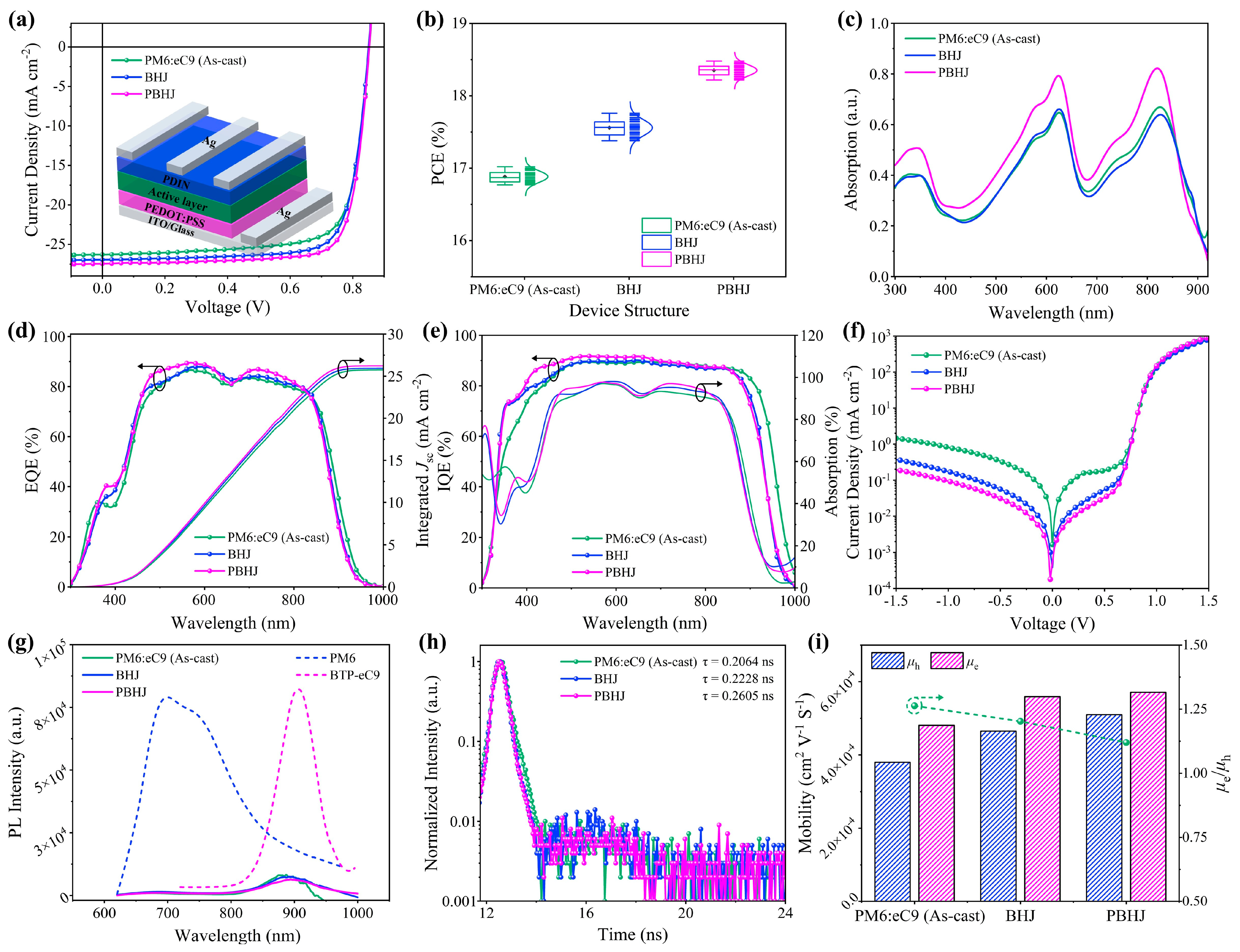
| PM6:BTP-eC9 | As-cast | 0.853 | 26.30 | 75.85 | 17.02 | 16.90 ± 0.13 | 95.26 | 16,746.24 |
| BHJ | 0.851 | 26.93 | 77.48 | 17.76 | 17.57 ± 0.18 | 83.55 | 22,482.77 | |
| PBHJ | 0.852 | 27.45 | 79.01 | 18.48 | 18.35 ± 0.13 | 74.68 | 29,320.11 | |
| PTQ10:BTP-eC9 | BHJ | 0.883 | 24.75 | 72.34 | 15.81 | 15.66 ± 0.15 | 101.56 | 18,478.11 |
| PBHJ | 0.885 | 25.56 | 74.39 | 16.83 | 16.72 ± 0.11 | 98.17 | 20,853.32 |
Disclaimer/Publisher’s Note: The statements, opinions and data contained in all publications are solely those of the individual author(s) and contributor(s) and not of MDPI and/or the editor(s). MDPI and/or the editor(s) disclaim responsibility for any injury to people or property resulting from any ideas, methods, instructions or products referred to in the content. |
© 2025 by the authors. Licensee MDPI, Basel, Switzerland. This article is an open access article distributed under the terms and conditions of the Creative Commons Attribution (CC BY) license (https://creativecommons.org/licenses/by/4.0/).
Share and Cite
Cao, J.; Xu, Z. The Pseudo-Bilayer Bulk Heterojunction Active Layer of Polymer Solar Cells in Green Solvent with 18.48% Efficiency. Polymers 2025, 17, 284. https://doi.org/10.3390/polym17030284
Cao J, Xu Z. The Pseudo-Bilayer Bulk Heterojunction Active Layer of Polymer Solar Cells in Green Solvent with 18.48% Efficiency. Polymers. 2025; 17(3):284. https://doi.org/10.3390/polym17030284
Chicago/Turabian StyleCao, Jingyue, and Zheng Xu. 2025. "The Pseudo-Bilayer Bulk Heterojunction Active Layer of Polymer Solar Cells in Green Solvent with 18.48% Efficiency" Polymers 17, no. 3: 284. https://doi.org/10.3390/polym17030284
APA StyleCao, J., & Xu, Z. (2025). The Pseudo-Bilayer Bulk Heterojunction Active Layer of Polymer Solar Cells in Green Solvent with 18.48% Efficiency. Polymers, 17(3), 284. https://doi.org/10.3390/polym17030284