Abstract
Static-cyclic shear load tests and tensile tests on retrofitted masonry walls were conducted at UAS Fribourg for an evaluation of the newly developed retrofitting system, the S&P ARMO-System. This retrofitting system consists of a composite of carbon mesh embedded in a specially adapted high quality spray mortar. It can be applied with established construction techniques using traditional construction materials. The experimental study has shown that masonry walls reinforced by this retrofitting system reach a similar strength and a higher ductility than retrofits by means of bonded carbon fiber reinforced polymer sheets. Hence, the retrofitting system using carbon fiber meshes embedded in a high quality mortar constitutes a good option for static or seismic retrofits or reinforcements for masonry walls. However, the experimental studies also revealed that the mechanical anchorage of carbon mesh may be delicate depending on its design.
1. Introduction
In the Swiss norm series of 2003 [1], the required level of safety was adjusted to the Eurocode 8 and the seismic risk zones were adjusted to newer seismologic knowledge [2]. Thanks to new design methods, new buildings can now be constructed according to the norm’s requirements without significant extra costs. However, most buildings in Switzerland were constructed before 2003 and many would not withstand a design earthquake. Masonry buildings, in particular, are vulnerable to earthquake loading, as masonry walls exhibit a reduced bearing capacity for horizontal loads combined with a rather high stiffness. If the seismic safety cannot be guaranteed, retrofitting existing masonry structures by means of composite materials, such as fiber reinforced polymers (FRP) may be a solution. A retrofit of masonry walls using FRP can be performed quickly and without deep intervention in the load carrying structure of the building. Various types incorporating different materials, forms, and orientations (uni- or bidirectional) of FRP are available (e.g. [3]). Different kinds of retrofits including different materials have been widely examined in research projects (e.g. [4,5,6,7,8]). At UAS Fribourg, the retrofitting of masonry walls has also been a major research topic since 2007, including [9,10,11]. Theoretical studies and experimental campaigns at UAS Fribourg have mainly focused on the use of high performance fibers (carbon, glass, aramid) in different applications.
This paper presents an experimental study of a newly developed retrofitting system (S&P ARMO-System) using carbon fiber meshes embedded in a high quality mortar. This system can be applied with established construction techniques using traditional construction materials. It is cost-efficient as its application can be carried out without experts, renouncing the usage of synthetic products, such as polymeric adhesive and leveling compound, and does not require extensive surface preparation.
In order to study the retrofitting system, four experimental series were conducted: In the first series, Series MR-C, the behavior of retrofitted masonry walls under static-cyclic loading was studied. In the second series, Series MT-A, the mechanical anchorage of carbon mesh embedded in different types of mortar was evaluated with tensile tests. In the third and fourth series, Series AT-F and Series AT-G, the mechanical anchorage of carbon mesh in adjacent concrete slabs or walls was analyzed with tensile tests. The tensile tests in Series MT-A, Series AT-F, and Series AT-G were performed on masonry elements, which represent a tensile pier of a retrofitted masonry wall.
2. Retrofitting System
The studied retrofitting system consists of a coated carbon mesh (unidirectional or bidirectional bundles of carbon fibers), which is embedded in specially adapted high quality spray mortar, the ARMO-crete w, a one-component product based on inorganic binders, fibers, selected aggregates, and polymer. The bonding capacity between carbon fibers and mortar is achieved physically by diverting stresses between fibers and spray mortar and chemically by amorphous silica coated on fibers and a reactive component added to the spray mortar, both reacting to calcium silica hydrate. The chemical bonding has been improved and the fiber cross section has been changed by the manufacturer for the carbon mesh L500 during the experimental campaign. Therefore, both the old and the new technology of chemical bonding have been tested. In Table 1, the material properties of the high quality mortar and the used carbon meshes are given.
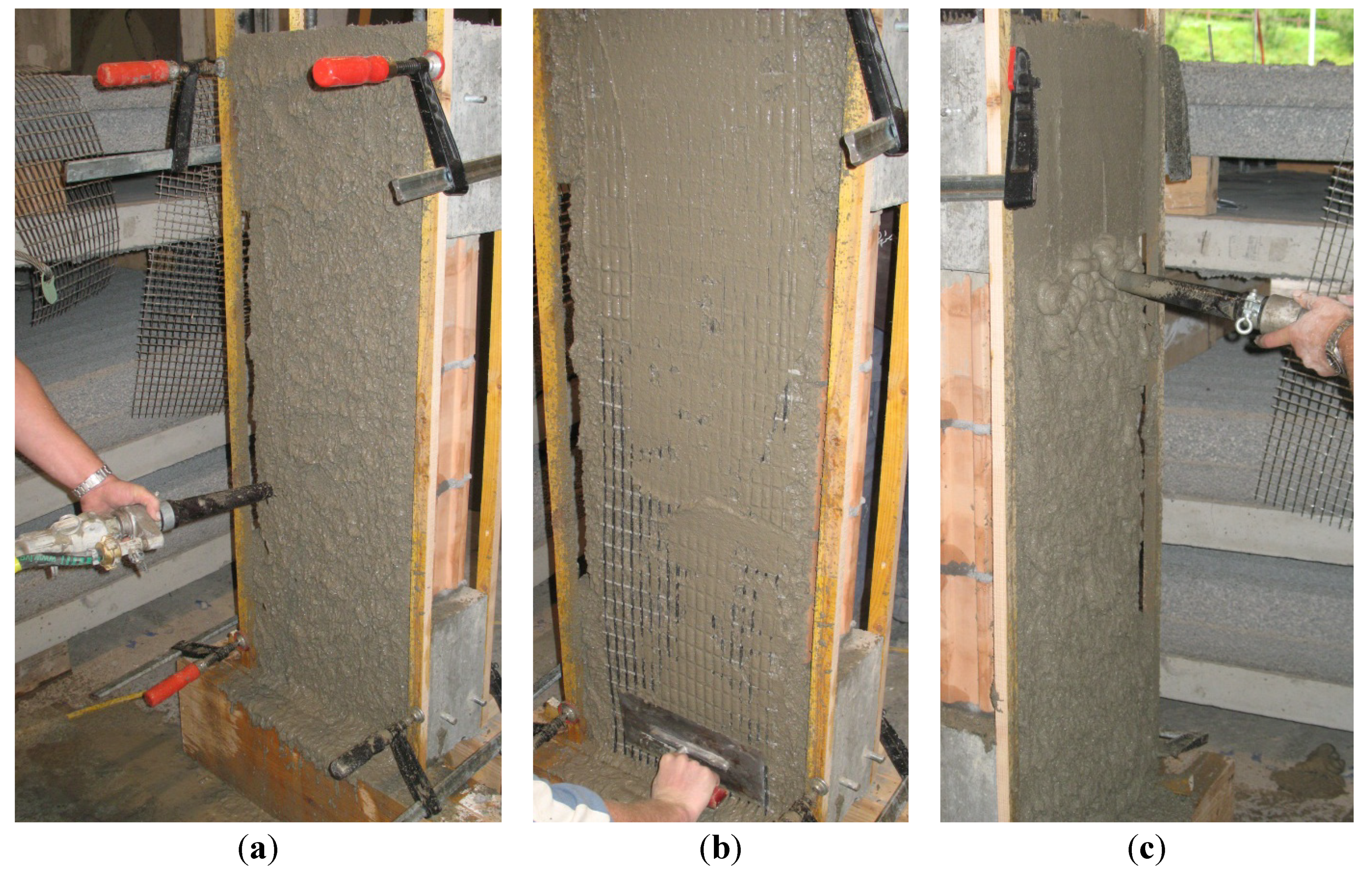
This retrofitting system can easily be applied. After cleaning masonry and concrete surfaces with a high pressure water gun, a first layer of mortar is applied. The carbon mesh is placed upon this layer whereby it is important to orientate all the carbon fibers of the mesh. In case a mechanical anchorage is used, the mesh is fixed on the anchoring profile. After placing and possibly fixing the mesh, a second layer of mortar is applied. The whole retrofit results in a thickness between 15 and 25 mm. If necessary, two layers of carbon meshes can be used resulting in a thickness between 25 and 35 mm. Different construction steps of the retrofitting system are shown in Figure 1.

Table 1.
Material properties of ARMO-crete w and used carbon meshes according to manufacturer [12].
| ARMO-crete w | Carbon meshes | L200 | L500 (old/new) | |
|---|---|---|---|---|
| Max. grain size (mm) | 2 | Elastic modulus (N/mm2) | 240,000 | 240,000 |
| Density (kg/m3) | 2,050 | Elongation at rupture (theoretical) (%) | 1.5 | 1.5 |
| Compressive strength (N/mm2), SN EN 12504-1 | >45 | Ultimate tensile strength (theoretical) (N/mm2) | 4,000 1 | 4,000 1 |
| Bond strength (N/mm2), SN EN 1542 | >1.5 | Cross section C-fiber (theoretical) (mm2/m) | 47 | 117/105 |
Note: 1 The manufacturer recommends limiting the design tensile stress for axial loading to ~650 N/mm2 (limit strain at ultimate state εu 0.4%).
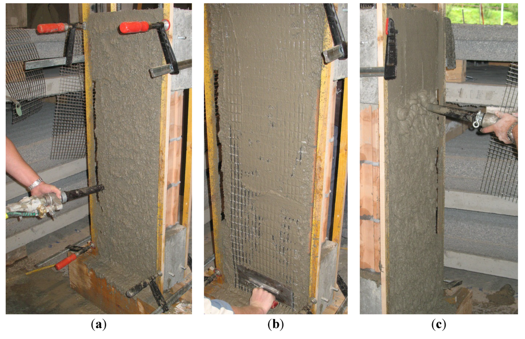
Figure 1.
Construction of retrofitted masonry element. (a) Application of a layer of spray mortar; (b) Embedding the carbon mesh; and (c) Application of another layer of spray mortar.
Figure 1.
Construction of retrofitted masonry element. (a) Application of a layer of spray mortar; (b) Embedding the carbon mesh; and (c) Application of another layer of spray mortar.
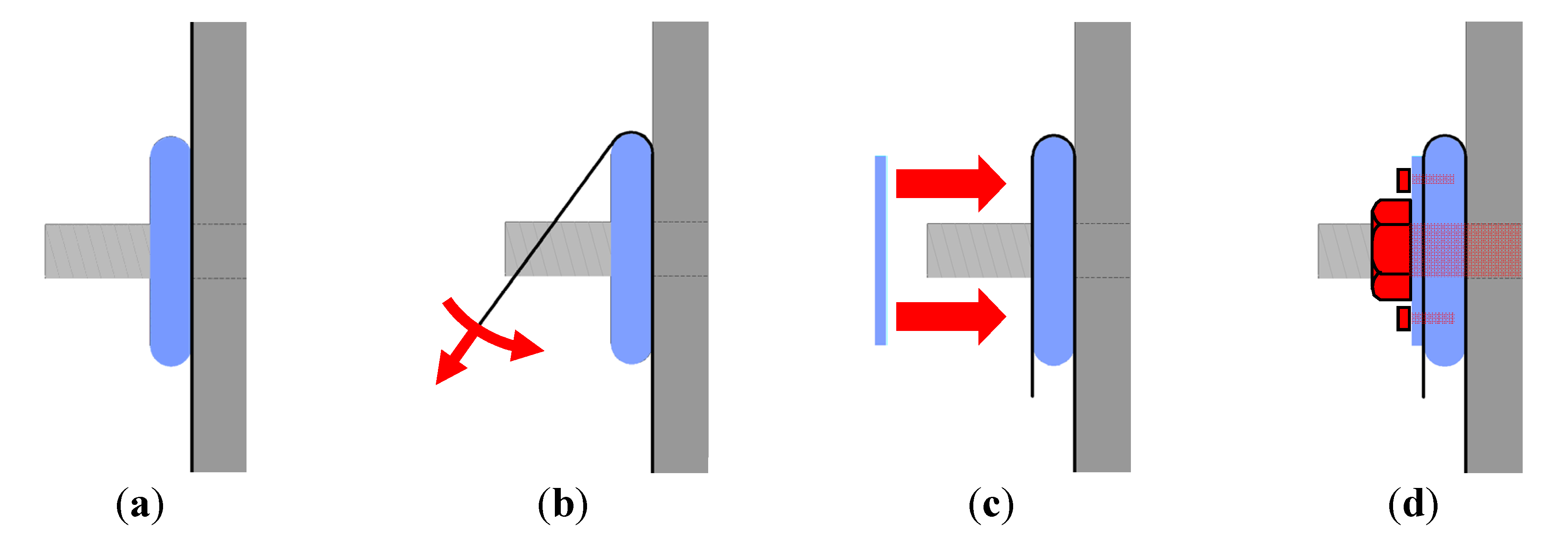
An aluminum profile was designed for the mechanical anchorage of the carbon mesh. All carbon fibers need to be pre-stressed evenly when being wrapped around the aluminum profile in order to avoid local fiber stress concentrations. The carbon mesh is fixed on the aluminum profile by a small metal plate. This metal plate and the aluminum profile are fixed with mechanical fasteners in the adjacent concrete. The performance of this mechanical anchorage was tested in Series MT-A, Series AT-F and Series AT-G. Different construction steps of the application of the aluminum profile as mechanical anchorage for the carbon mesh are shown in Figure 2.
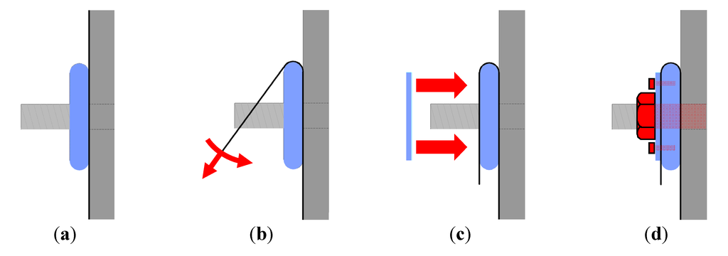
Figure 2.
Mechanical anchorage of carbon mesh with aluminum profile. (a) Application of aluminum profile; (b) Pre-stressing the mesh fibers when wrapping them around the aluminum profile; (c) Fixation of mesh by metal plate; and (d) Fixation of aluminum profile and metal plate in adjacent concrete.
Figure 2.
Mechanical anchorage of carbon mesh with aluminum profile. (a) Application of aluminum profile; (b) Pre-stressing the mesh fibers when wrapping them around the aluminum profile; (c) Fixation of mesh by metal plate; and (d) Fixation of aluminum profile and metal plate in adjacent concrete.
3. Static-Cyclic Tests on Retrofitted Masonry Walls
3.1. Experimental Program
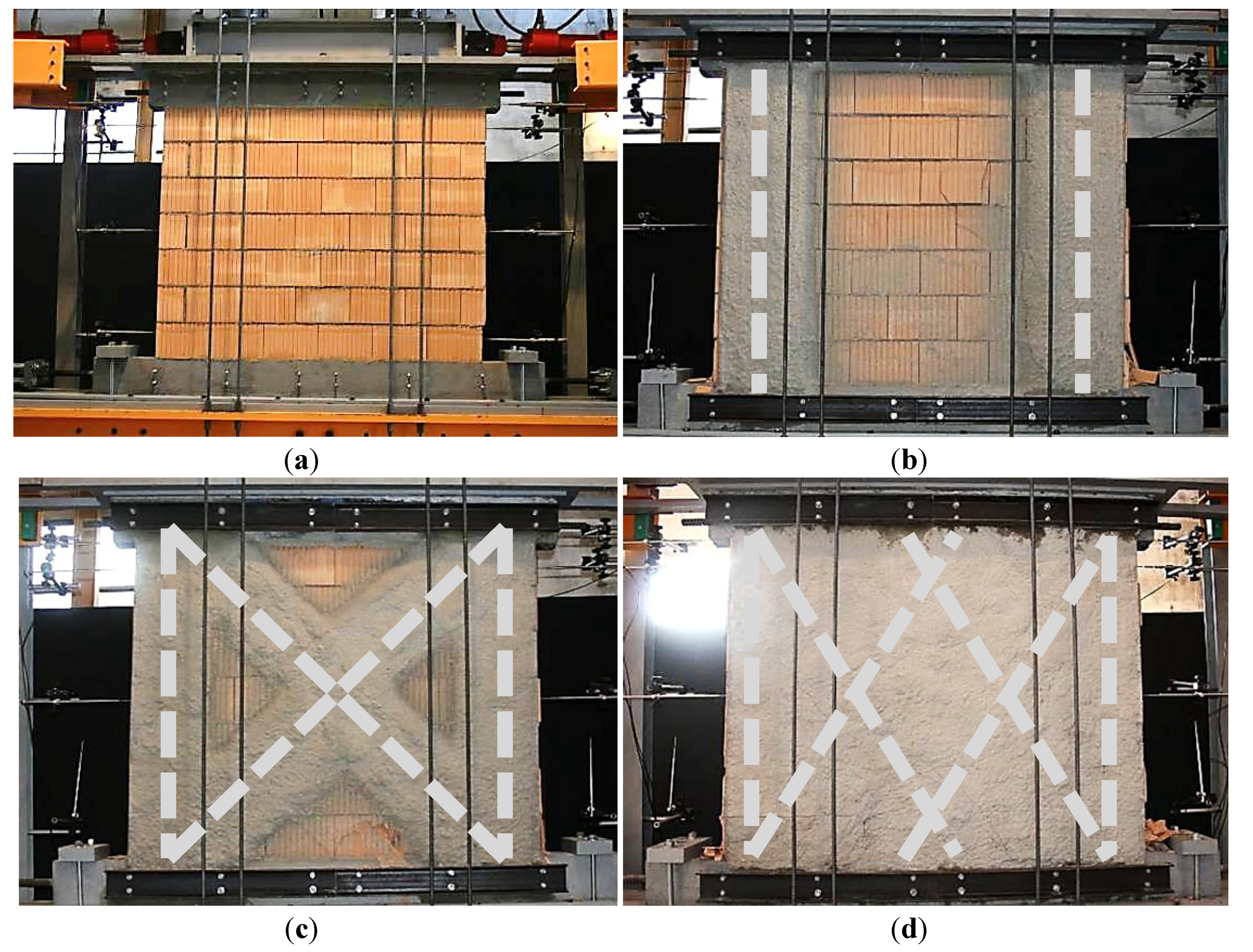
In Series MR-C, five masonry walls (height: 1400 mm, length: 1800 mm, thickness: 150 mm) were tested. Four were retrofitted through carbon meshes L500 (width of mesh strips: 300 mm, old technology), which were embedded in high quality mortar, whereas one served as a reference wall without retrofit. The retrofit was only applied on one face of each wall. Even though this creates a small eccentricity, the influence on the shear capacity and the deformability is negligible [13]. The tested configurations are summarized in Figure 3 and Table 2.
The masonry walls were built between two RC-beams (length: 2000 mm, thickness: 200 mm, width: 150 mm), which represented RC-slabs below and above the masonry wall. The carbon mesh was mechanically anchored with U-formed steel profiles (UPN 120), which were themselves mechanically fastened in the RC-beams. The vertical and the horizontal load were applied through the upper RC-beam.

Table 2.
Tested configurations of retrofitted masonry walls in Series MR-C.
| Specimen | Type of carbon mesh | Retrofit configuration |
|---|---|---|
| MR-C1 | Reference wall, no retrofit | |
| MR-C2 | L500 | Two vertically applied carbon mesh strips |
| MR-C3 | L500 | Two vertically and two diagonally (45°) applied carbon mesh strips |
| MR-C4 | L500 | Two vertically and four diagonally (45°, two layers) applied carbon mesh strips |
| MR-C5 | L500 | Two vertically and four diagonally (60°) applied carbon mesh strips |
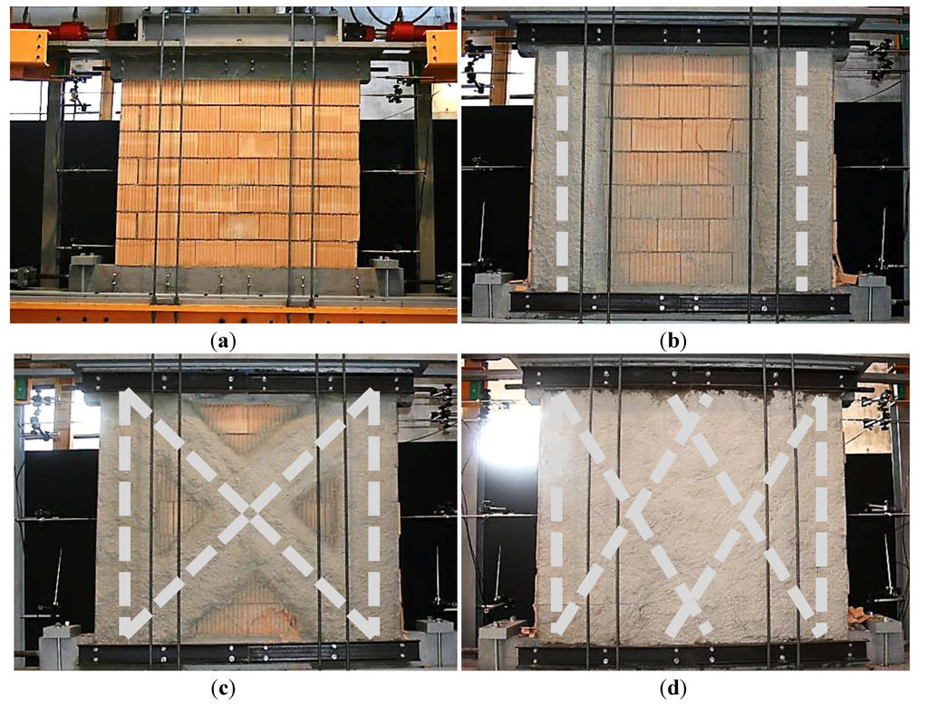
Figure 3.
Different configurations of carbon mesh for retrofitting masonry walls in Series MR-C. (a) MR-C1; (b) MR-C2; (c) MR-C3/MR-C4 (two layers); and (d) MR-C5.
Figure 3.
Different configurations of carbon mesh for retrofitting masonry walls in Series MR-C. (a) MR-C1; (b) MR-C2; (c) MR-C3/MR-C4 (two layers); and (d) MR-C5.
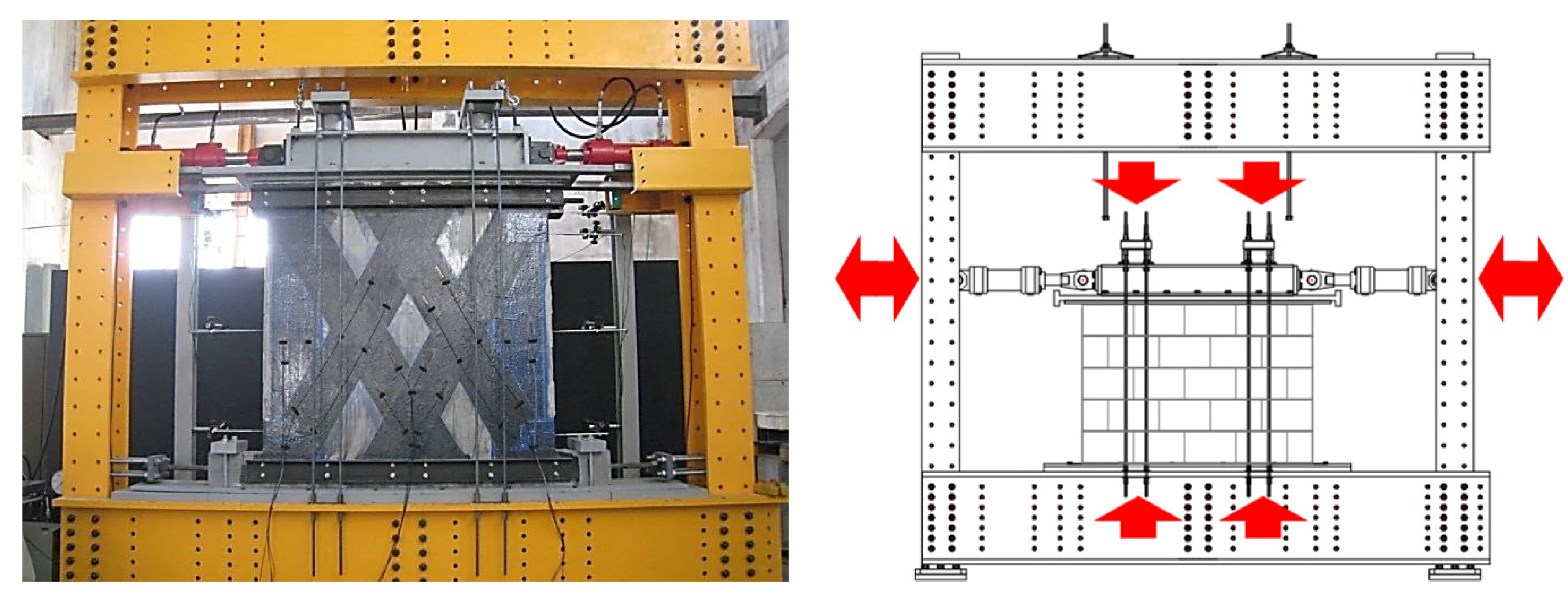
The static-cyclic shear load tests in Series MR-C were carried out on a set-up specifically designed for this research project (Figure 4). This test set-up allowed for the application of normal and horizontal forces at the same time. The static-cyclic test process was performed as follows:
- Firstly, a vertical load of 135 kN corresponding to a distributed load of 0.5 N/mm2 was applied by two hydraulic actuators with a capacity of 1000 kN each. This vertical load was kept approximately constant during the entire test. The difference of the vertical load in each pier caused by cyclic horizontal loading was 0.1 N/mm2 maximum and, hence, not decisive for the experimental results.
- Secondly, a horizontal load was applied by two actuators with a capacity of +200/−300 kN each. Both were independently connected to an individual hydraulic system. The horizontal force was progressively and alternatively increased on each side, until the first crack occurred. The test was then driven by deformation until the ultimate limit state was reached and complete failure occurred.
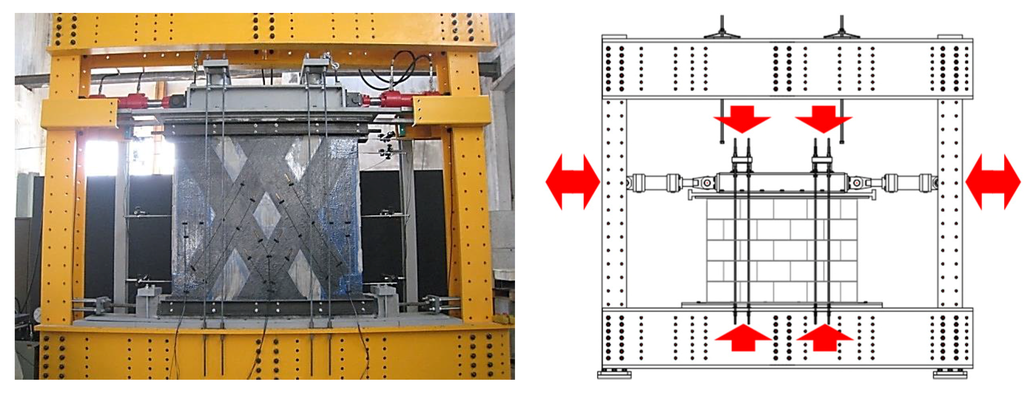
Figure 4.
Set-up for static-cyclic load tests.
Figure 4.
Set-up for static-cyclic load tests.
3.2. Test Results
The load-displacement curves of the retrofitted masonry walls in Series MR-C are shown in Figure 5. A summary of the maximum applied load and the maximum reached deformation at the top of the wall is given in Table 3.

Table 3.
Horizontal force and maximum displacement at the top of the wall in Series MR-C.
| Specimen | Fmax+ (kN) | Fmax− (kN) | Comparison to reference wall | 0.8Fmax+ (kN) | 0.8Fmax− (kN) | δu+ (mm) | δu− (mm) | Comparison to reference wall |
|---|---|---|---|---|---|---|---|---|
| MR-C1 | 75.2 | 76.8 | 100% | 60.2 | 61.4 | 10.1 | 10.2 | 100% |
| MR-C2 | 110.0 | 110.0 | 145% | 88.0 | 88.0 | 14.5 | 13.6 | 138% |
| MR-C3 | 109.0 | 114.0 | 147% | 87.2 | 91.2 | 11.8 | 10.8 | 111% |
| MR-C4 | 121.0 | 120.0 | 159% | 96.8 | 96.0 | 12.0 | 12.2 | 119% |
| MR-C5 | 121.0 | 122.0 | 161% | 96.8 | 97.6 | 10.8 | 11.2 | 108% |
All five walls behaved very stiffly in the beginning. At a horizontal load of 50 kN and a horizontal deformation of 1 mm, cracking initiated in specimens MR-C1 and MR-C2 with an angle of about 60° with respect to the horizontal, which corresponds to the inclination of the diagonal compression strut. In specimens MR-C3 to MR-C5 with diagonal shear reinforcement, the masonry remained without cracks up to a horizontal force of about 80 kN. In all cases cracking initiated at the lower angles of the masonry wall.
Failure always occurred when the masonry wall reached its compression capacity due to the superposition of the diagonal compression strut and the axial normal force. Compression failure of masonry happened either locally at the lower angles for specimens without shear reinforcement or over the whole length for specimens with shear reinforcement. The failed specimens are shown in Figure 6.
Compared to the reference wall (MR-C1), the ultimate load was increased up to 161% (MR-C5), whereas the deformability was increased up to 138%. (MR-C2) The maximum applied load and the deformation behavior in Series MR-C are mostly equivalent to those received in the experimental series with bonded CFRP sheets retrofitting masonry walls (Series MR-B, [9]).
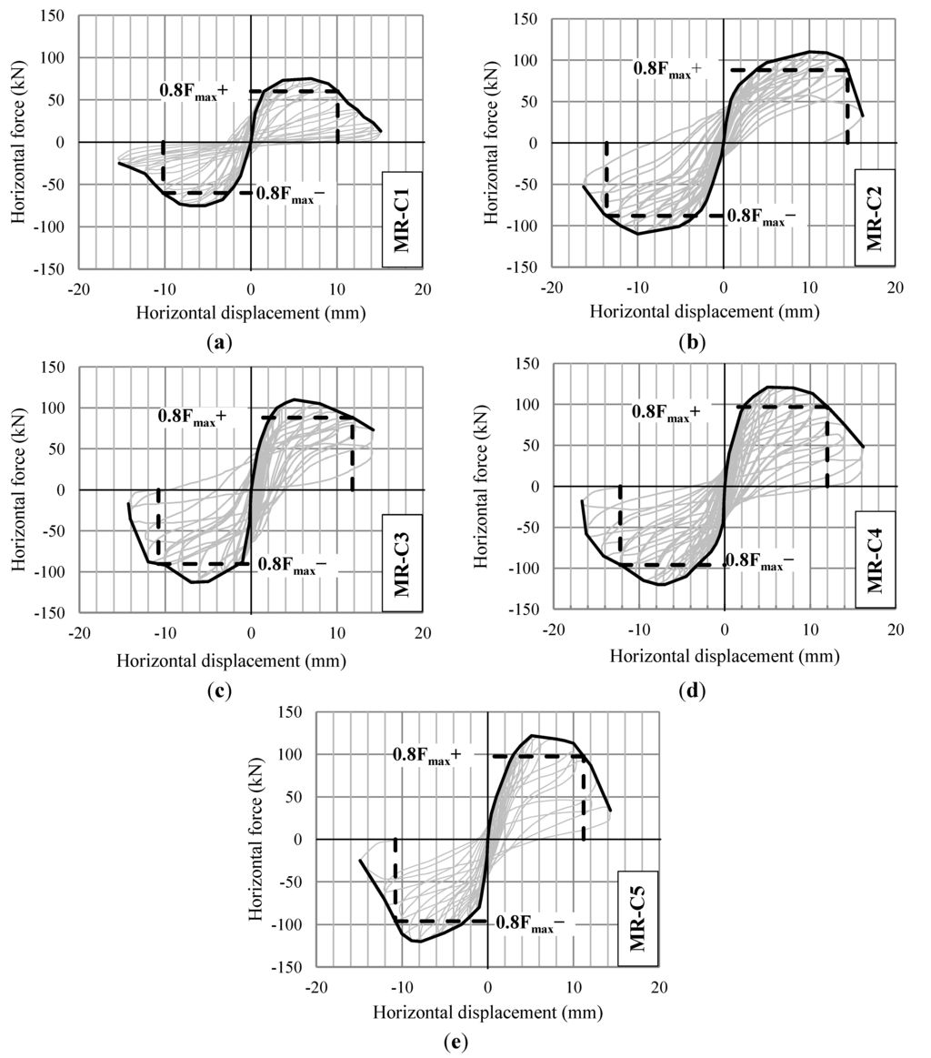
Figure 5.
Load-displacement curves in Series MR-C. (a) MR-C1; (b) MR-C2; (c) MR-C3; (d) MR-C4; and (e) MR-C5.
Figure 5.
Load-displacement curves in Series MR-C. (a) MR-C1; (b) MR-C2; (c) MR-C3; (d) MR-C4; and (e) MR-C5.
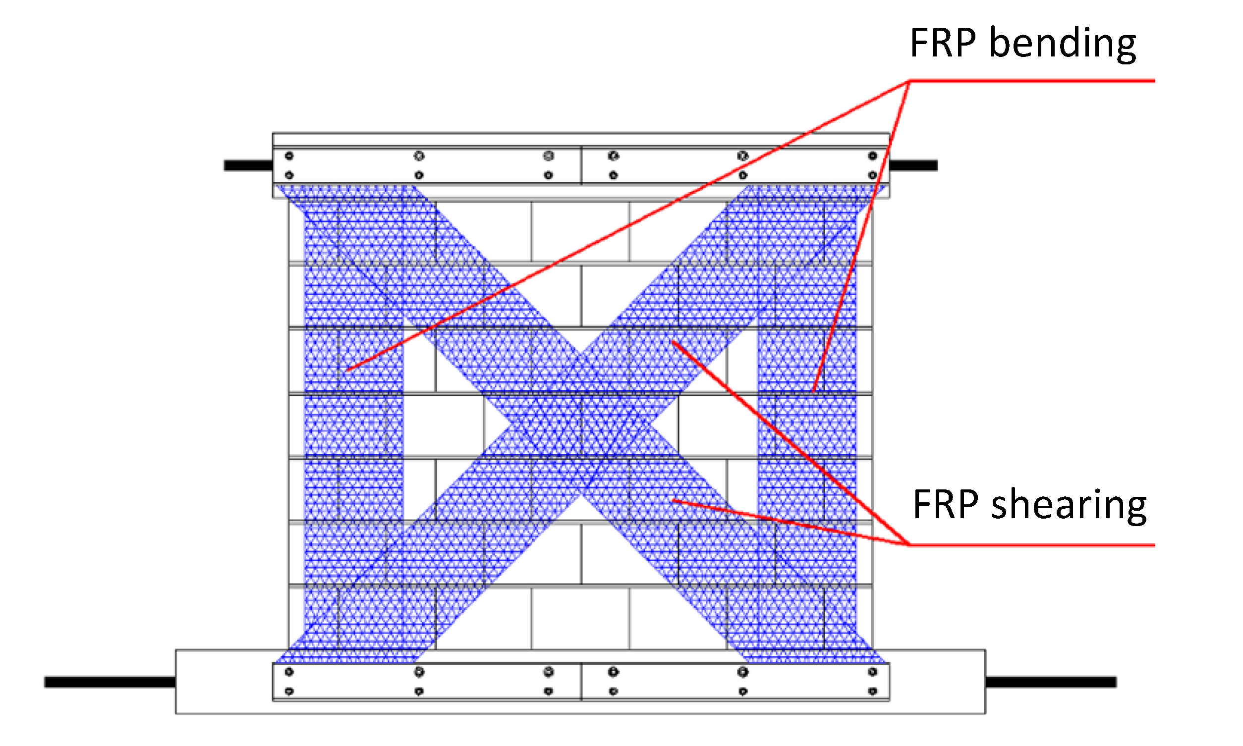
The vertical reinforcement inhibits rocking. Rocking plays a crucial role in the behavior of unreinforced masonry walls (e.g. [14]). The diagonally applied reinforcement strongly enhances the shear capacity. The closer the inclination angle of the diagonal carbon strips moves from 45° towards 90° with respect to the horizontal, the less the shear capacity is enhanced. The analysis of this tension and compression strut creates the possibility to design according to the truss analogy (Figure 7) or according to stress fields. Obviously, the vertical component induced by the horizontal force from seismic loading must be added to the vertical load acting on the wall without seismic loading.
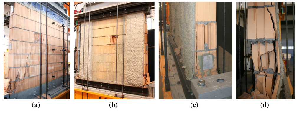
Figure 6.
Failed specimens in Series MR-C. (a) and (b) MR-C2; (c) MR-C3; and (d) MR-C5.
Figure 6.
Failed specimens in Series MR-C. (a) and (b) MR-C2; (c) MR-C3; and (d) MR-C5.
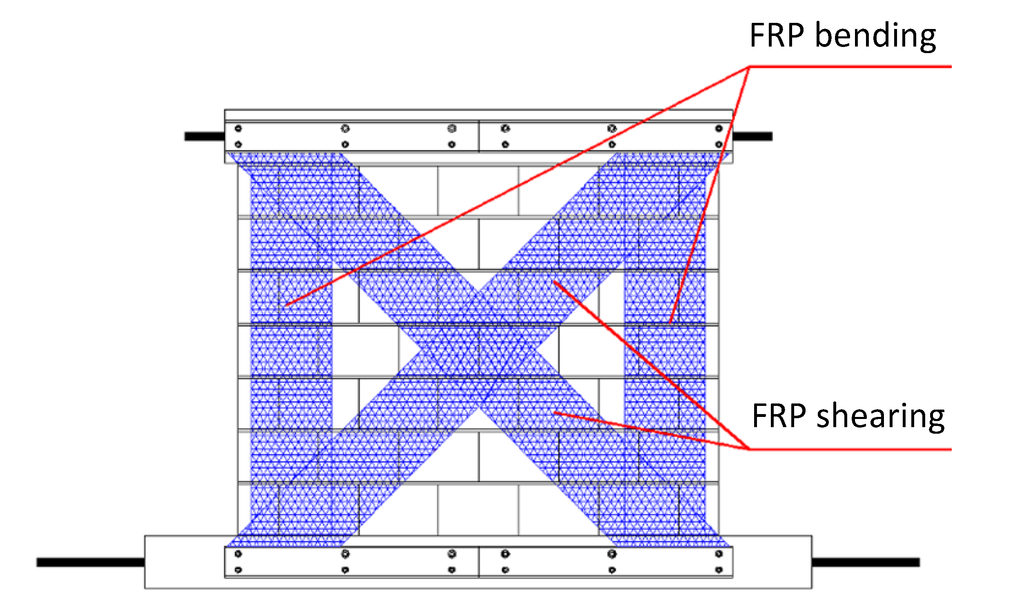
Figure 7.
State of stress in retrofitted masonry wall.
Figure 7.
State of stress in retrofitted masonry wall.
The ACI (American Concrete Institute, Farmington Hills, MI, USA) has published recommendations to calculate the contribution of diagonal FRP sheets on masonry walls [15]. Furthermore, the Italian CNR (National Research Committee, Rome, Italy) has established a guidance to evaluate the mean debonding fiber stresses of vertical and horizontal FRP sheets [16].
4. Tensile Tests on Retrofitted Masonry Walls
4.1. Experimental Program
In Series MT-A, tensile tests were carried out on masonry elements reinforced with carbon mesh. These elements represent a pier of a reinforced masonry wall. The deformation and the cracking of tensile elements have been analyzed in detail. The tensile tests were conducted on a test set-up, which allowed for a uniform load application up to 1000 kN and for deformation up to 160 mm (Figure 8a). The tests could either be carried out controlling the load application or controlling the deformation. Six masonry elements (height: 1800 mm, width: 600 mm, thickness: 150 mm) were retrofitted by embedding carbon mesh into mortar on both front and back sides. For the load application and for the fixation of mechanical anchorage of the carbon meshes, concrete blocks were installed at the top and at the bottom (Figure 8b,c).
The studied retrofitting system was principally developed for the reinforcement of existing structures. However, it may possibly also be used for new masonry walls. Therefore, the tensile tests were not only carried out with the mortar ARMO-crete w, specifically developed for the ARMO-System, but also with standard mortar used as exterior (Fixit 610, PC mortar) and interior plaster (Fixit 180, low resistance gypsum mortar). By embedding the carbon mesh in the mortar, “reinforced masonry walls” can be constructed.
For specimens MT-A1/A2/A3/A4, the carbon mesh was mechanically anchored through U-formed steel profiles (UPN 120), which were fastened and pressed against the composite mesh-mortar. For specimens MT-A5 and MT-A6, the carbon mesh was mechanically anchored with the aluminum profiles presented in Section 2.
The following parameters were varied throughout Series MT-A: quality of mortar, thickness of carbon mesh, and mechanical anchorage. The resulting six configurations are summarized in Table 4.
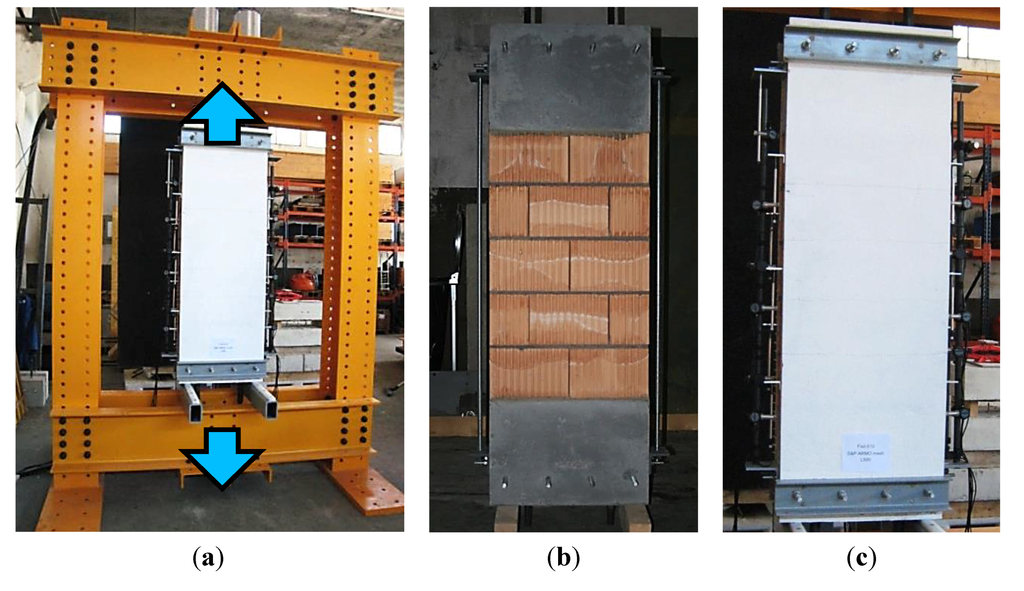
Figure 8.
(a) Test set-up for tensile tests on retrofitted masonry elements; (b) Test specimen before retrofitting; and (c) Test specimen after retrofitting.
Figure 8.
(a) Test set-up for tensile tests on retrofitted masonry elements; (b) Test specimen before retrofitting; and (c) Test specimen after retrofitting.
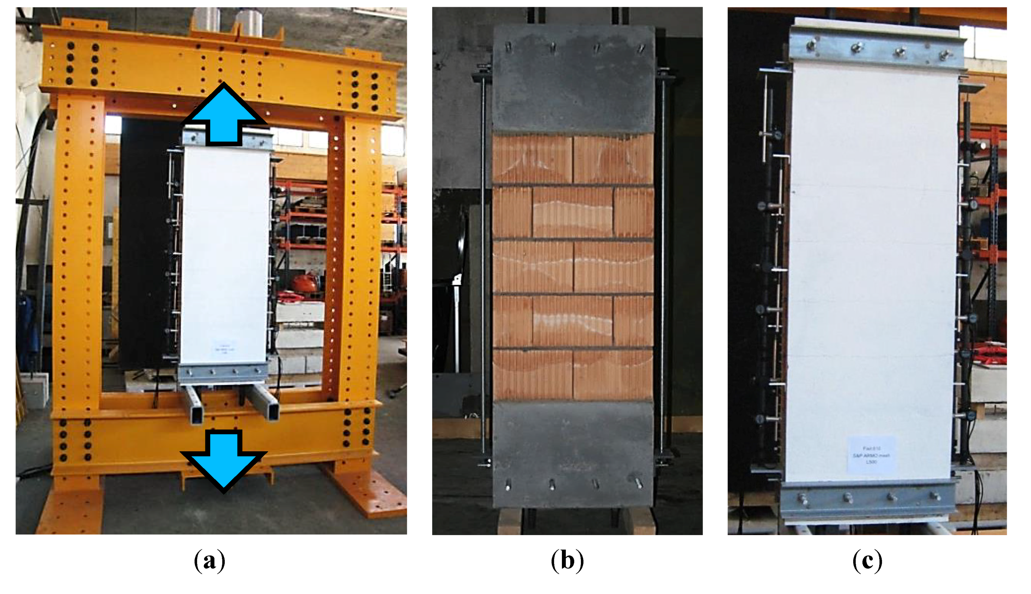

Table 4.
Tested configurations of retrofitted masonry elements in Series MT-A.
| Specimen | Type of carbon mesh | Type of mortar | Mechanical anchorage |
|---|---|---|---|
| MT-A1 | L500 (old) | Fixit 610 | Mesh pressed |
| MT-A2 | L200 | Fixit 610 | Mesh pressed |
| MT-A3 | L500 (old) | Fixit 180 | Mesh pressed |
| MT-A4 | L200 | Fixit 180 | Mesh pressed |
| MT-A5 | L500 (old) | ARMO-crete w | Mesh wrapped |
| MT-A6 | L200 | ARMO-crete w | Mesh wrapped |
4.2. Test Results
The load-displacement curves of the retrofitted masonry elements in Series MT-A are shown in Figure 9. A summary of the maximum applied load and the corresponding fiber stresses, deformations, and strains are shown in Table 5. The strains are only shown for the specimens with a complete fixation of the carbon mesh.
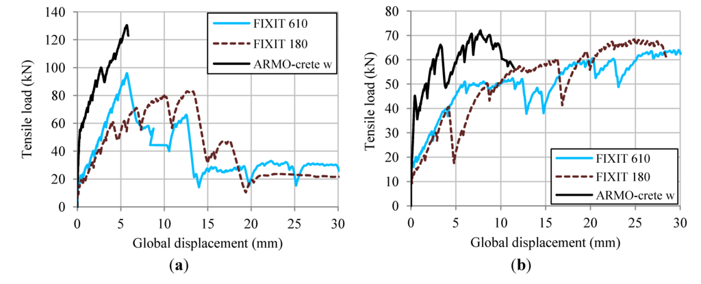
Figure 9.
Load-displacement curves. (a) Specimens MT-A1/A3/A5 with mesh L500; and (b) Specimens MT-A2/A4/A6 with mesh L200.
Figure 9.
Load-displacement curves. (a) Specimens MT-A1/A3/A5 with mesh L500; and (b) Specimens MT-A2/A4/A6 with mesh L200.
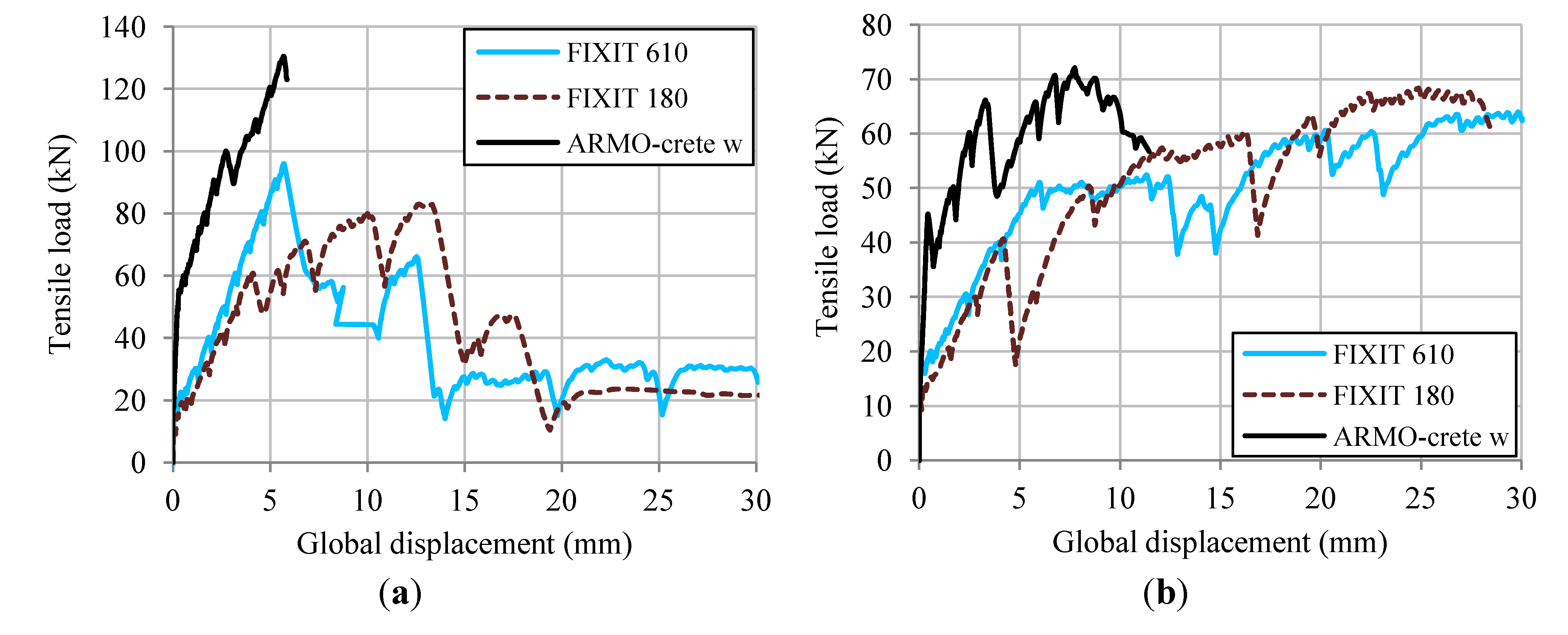

Table 5.
Test results of Series MT-A.
| Specimen | Fmax (kN) | Fmax/Ru 1 (−) | σmax (N/mm2) | δ(Fmax) (mm) | ε(Fmax) (%) |
|---|---|---|---|---|---|
| MT-A1 | 95 | 0.17 | 679 | 5.7 | - |
| MT-A2 | 64 | 0.29 | 1143 | 29.8 | - |
| MT-A3 | 84 | 0.15 | 600 | 13.1 | - |
| MT-A4 | 68 | 0.30 | 1214 | 24.9 | - |
| MT-A5 | 132 | 0.24 | 943 | 5.7 | 0.35% |
| MT-A6 | 73 | 0.33 | 1304 | 7.8 | 0.48% |
Note: 1 Ru represents the theoretical ultimate tensile strength.
The tests have shown that until first cracks occur, the behavior of the masonry elements depends on the mechanical properties of the mortar. In the case of Fixit 610, first cracks occur at an applied tensile load of approximately 20 kN corresponding to 0.2 N/mm2 in the mortar. In the case of Fixit 180, first cracks occur at an applied tensile load of 10 kN. In the case of ARMO-crete w, first cracks occur at a considerably higher load of approximately 50 kN.
The mesh L500 cannot be sufficiently anchored by pressing the steel profile against the mortar, as the considerable difference of the maximum applied fiber stress in MT-A1 and MT-A3 with the mesh L500 compared to the maximum applied fiber stress in MT-A2 and MT-A4 with the mesh L200 shows. The mesh L200 brought about positive results with any type of mortar. The maximum applied tensile stress between 1100 and 1300 N/mm2 is considerably higher than the limit of the design tensile stress for axial loading (650 N/mm2) recommended by the manufacturer. Due to the swelling and shrinking of gypsum, the use of Fixit 180 for reinforced masonry walls should, however, be avoided when the wall is exposed to humidity changes.
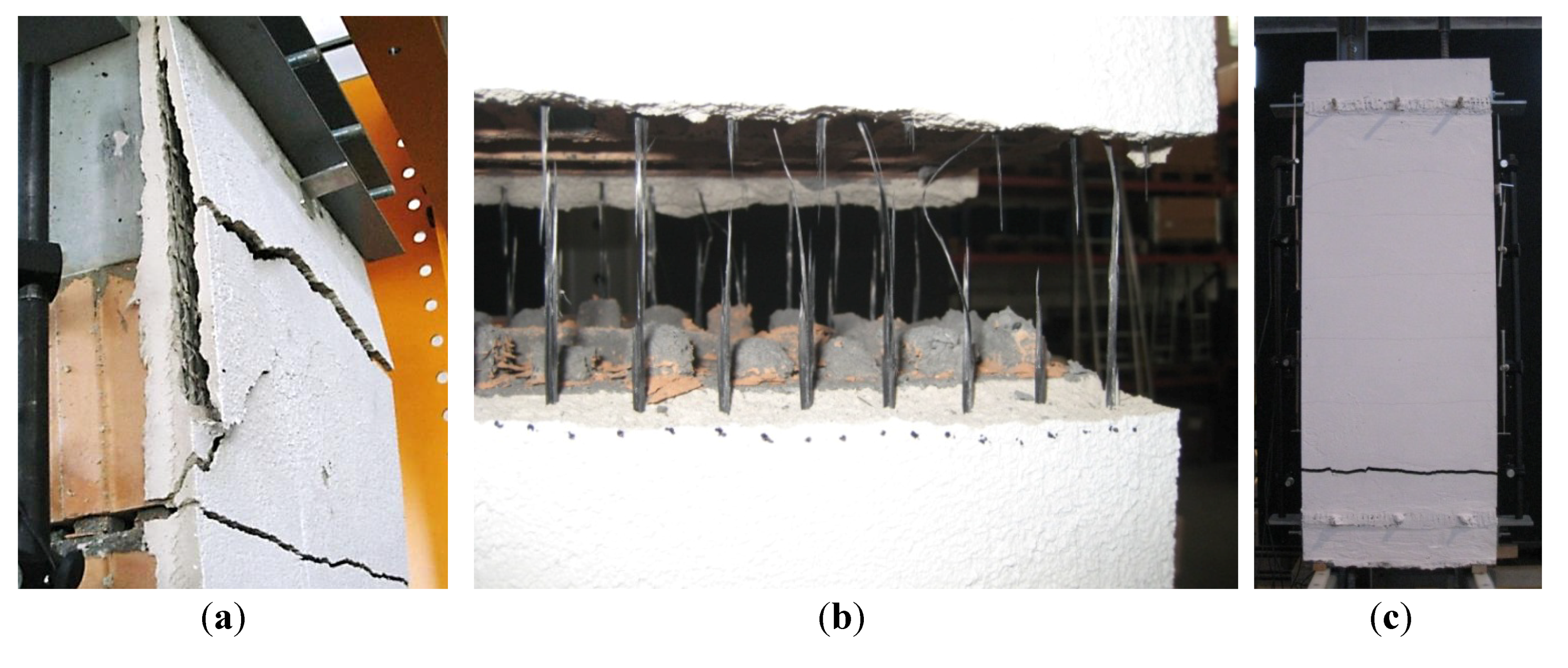
In MT-A5 and MT-A6, where the carbon mesh was wrapped around the mechanical anchorage, the maximum applied tensile loads were higher. Nonetheless, a different anchorage weakness occurred. The carbon mesh is prone to premature fiber rupture if stress concentrations occur due to non-uniform pre-stress conditions. Failed test specimens are shown in Figure 10.
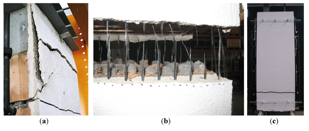
Figure 10.
Test specimens after failure. (a) Pulled out fibers from mechanical anchorage in specimens MT-A1/A3 (L500); (b) Fiber failure in specimens MT-A2/A4 (L200); and (c) Fiber failure in specimens with fixed mechanical anchorage.
Figure 10.
Test specimens after failure. (a) Pulled out fibers from mechanical anchorage in specimens MT-A1/A3 (L500); (b) Fiber failure in specimens MT-A2/A4 (L200); and (c) Fiber failure in specimens with fixed mechanical anchorage.
5. Tensile Tests on Mechanical Anchorage
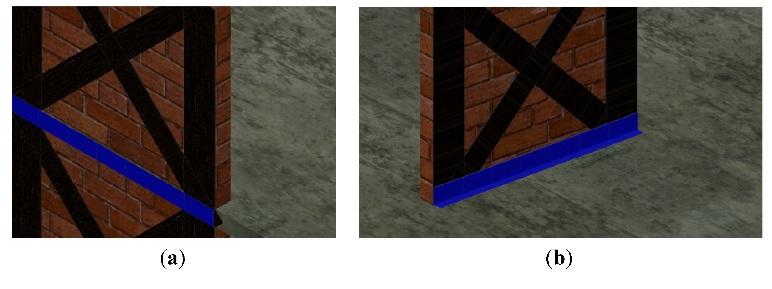
Depending on the location of unreinforced masonry walls in buildings that ought to be retrofitted, two different implementations of mechanical anchorages are possible. For exterior walls, the carbon mesh can be anchored in the slab edge (Figure 11a) whereas for interior walls, the carbon mesh has to be anchored in the slab perpendicular to the wall (Figure 11b). Series AT-F was conducted to study the former problem whereas Series AT-G was conducted to study the latter.
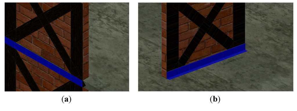
Figure 11.
Implementation of mechanical anchorage (a) for exterior walls and (b) for interior walls.
Figure 11.
Implementation of mechanical anchorage (a) for exterior walls and (b) for interior walls.
5.1. Experimental Program
5.1.1. Series AT-F
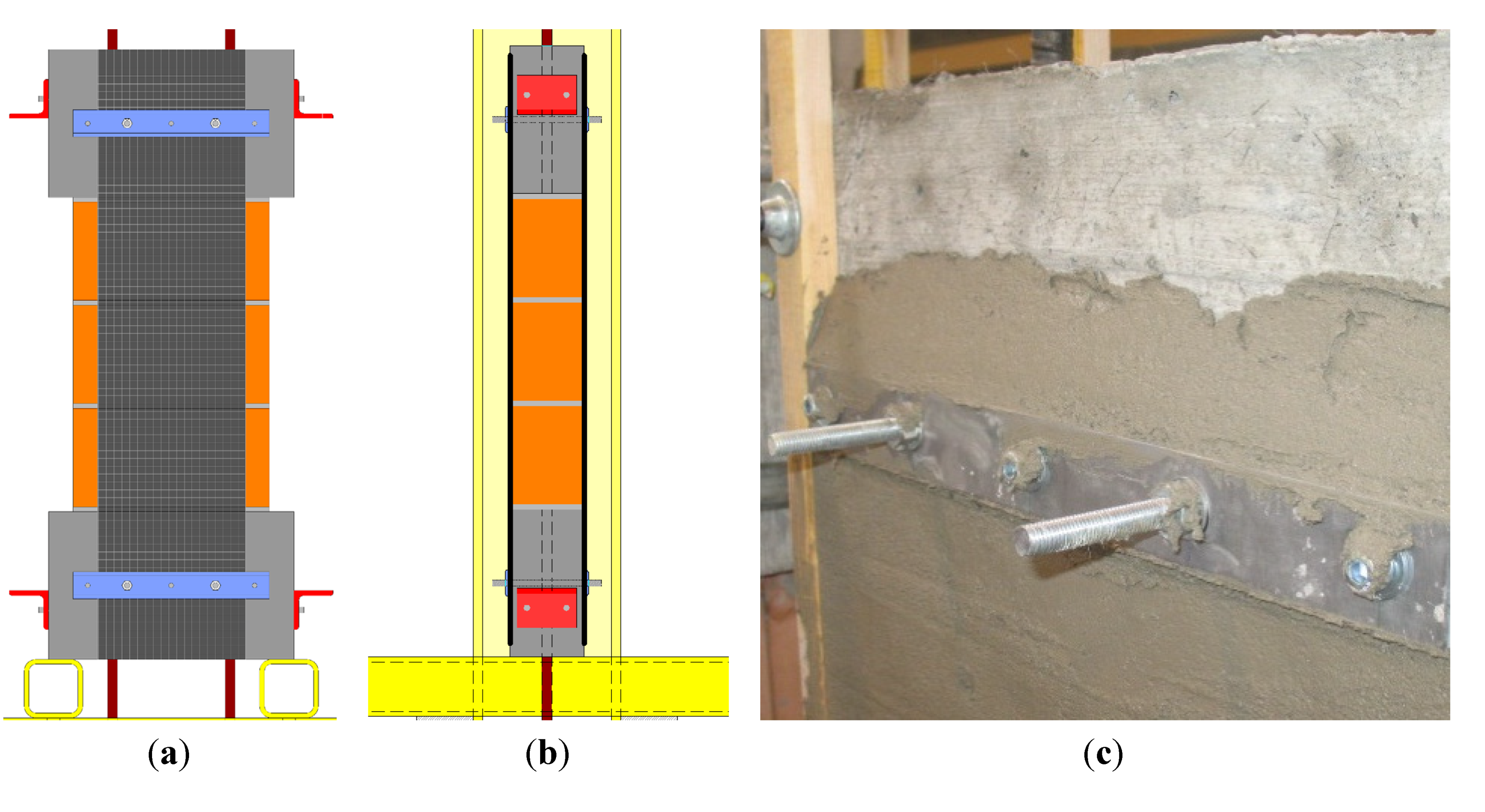
In Series AT-F, the mechanical anchorage of carbon meshes retrofitting masonry walls was studied in tensile tests. The tests were conducted on the same test set-up as Series MT-A (Figure 8a). Six masonry elements (height: 1200 mm, width: 300 mm, thickness: 150 mm), representing a pier of a reinforced masonry wall, were retrofitted by embedding 300 mm wide coated carbon mesh in high quality spray mortar on both front and back sides. For the load application and the fixation of the mechanical anchorage of the carbon meshes, concrete blocks were installed at the top and at the bottom. A model of a test specimen in Series AT-F in view and sectional drawing is shown in Figure 12a,b.
Test specimens AT-F1 and AT-F3 were tested without mechanical anchorage. For specimens AT-F2 and AT-F4, the carbon mesh was anchored with the aluminum profiles, presented in section 2, on the upper and the lower concrete block at front and back side (see Figure 12c). The aluminum profiles were fixed on horizontal steel rods, which were encased in the concrete block. The total thickness of the spray mortar with embedded mesh resulted in about 15 mm.
Specimens AT-F13 and AT-F14 were constructed in a slightly different manner. As for the other specimens, the mesh was embedded in the high quality spray mortar. However, the thickness of the spray mortar was reduced to approximately 10 mm in order to improve the compression effect on fibers. According to experience with CFRP strips [17], the pull-out strength of the carbon mesh should be improved through pressure applied by means of aluminum profiles. An aluminum profile was pressed on the mortar about 1h after the mortar’s application and was fixed with M16 screws after 28 days before the experiment by means of a torque wrench to 300 Nm.
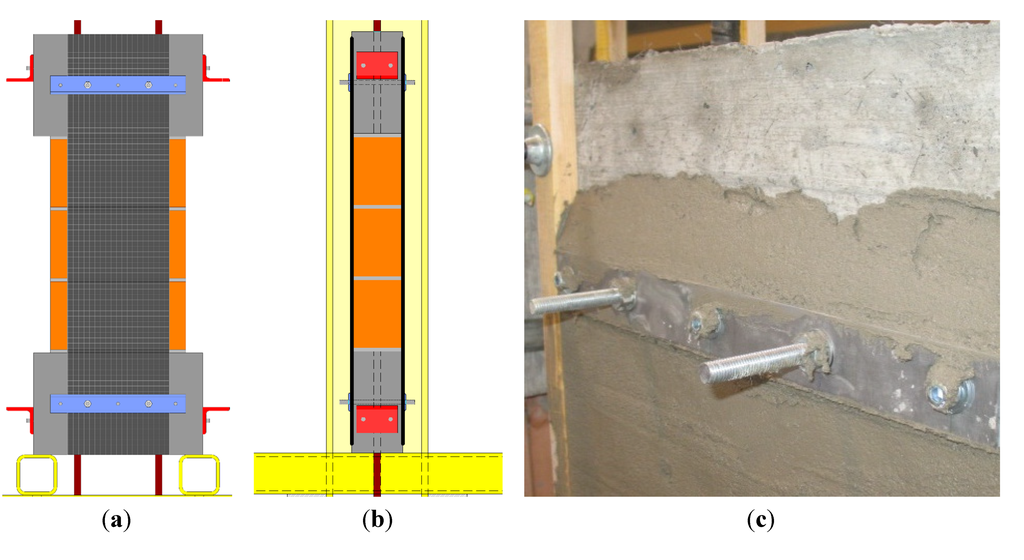
Figure 12.
(a,b) Model of specimen in Series AT-F in view and sectional drawing; and (c) Carbon mesh mechanically fixed by aluminum profile.
Figure 12.
(a,b) Model of specimen in Series AT-F in view and sectional drawing; and (c) Carbon mesh mechanically fixed by aluminum profile.
Based on results in preliminary tests [9], a serviceability fiber stress was defined to 600 N/mm2. Hence, the test specimens were loaded to 600 N/mm2 and completely unloaded in a first load cycle and loaded until failure in a second load cycle. The following parameters were varied throughout Series AT-F: thickness of carbon mesh and type of mechanical anchorage. The resulting six configurations are summarized in Table 6.

Table 6.
Tested configurations of retrofitted masonry elements in Series AT-F.
| Specimen | Carbon mesh type | Configuration of mechanical anchorage |
|---|---|---|
| AT-F1 | L200 | No mechanical anchorage |
| AT-F2 | L200 | Mesh wrapped around mechanical anchorage |
| AT-F3 | L500 (old) | No mechanical anchorage |
| AT-F4 | L500 (old) | Mesh wrapped around mechanical anchorage |
| AT-F13 | L500 (new) | Mesh pressed by mechanical anchorage |
| AT-F14 | L500 (new) | Mesh pressed by mechanical anchorage |
5.1.2. Series AT-G
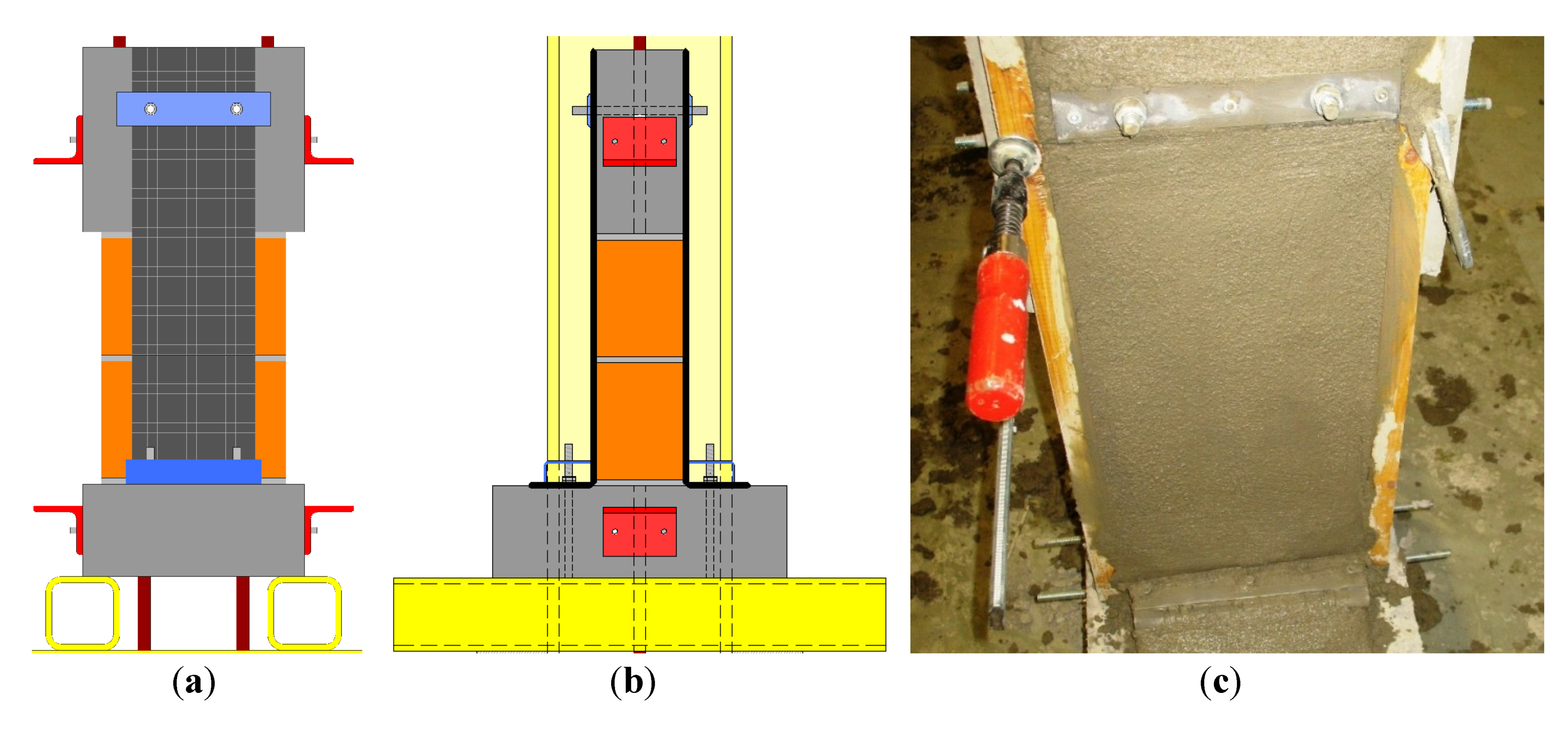
For Series AT-G, between the concrete blocks, small masonry elements incorporating two masonry bricks were constructed. These masonry elements were retrofitted by embedding 200 mm wide coated carbon mesh in high quality spray mortar. Figure 13a,b show a model of a test specimen in Series AT-G in view and sectional drawing. The tests were conducted on the same test set-up as Series MT-A (Figure 8a).
On construction site, the profiles forming the mechanical anchorage of interior walls can be fixed either with mechanical fasteners in the concrete slab or, in stories above the basement, with steel rods which directly connect two mechanical anchorages through the concrete slab between stories. In preliminary tests with CFRP sheets, the fixation with mechanical fasteners was tested [11]. Only with rather large profiles, it can be avoided that the mechanical fasteners are the critical element in the anchorage system. In Series AT-G, therefore, threaded steel rods were encased in the lower concrete block as a complete fixation for the mechanical anchorage.
For specimens AT-G1 and AT-G2, aluminum profiles were used for the mechanical anchorage in the lower concrete block. For all other specimens, rectangular hollow section (RHS) steel profiles were used. According to these different profiles of mechanical anchorage, the profile’s curvature radius differed. As the carbon mesh needs to be anchored around the profiles for retrofitting interior walls, different curvature radii cause different diverting stresses acting to the carbon mesh. At the upper concrete block, the carbon meshes were anchored in accordance to Series AT-F with aluminum profiles. Figure 13c shows the construction of a specimen in Series AT-G.
As in Series AT-F, the test specimens were loaded to 600 N/mm2 and completely unloaded in a first load cycle and loaded until failure in a second load cycle. The following parameters were varied throughout Series AT-G: thickness of carbon mesh and type of mechanical anchorage including curvature radius of profile.

Table 7.
Tested configurations of retrofitted masonry elements in Series AT-G.
| Specimen | Type of carbon mesh | Type mechanical anchorage bottom | Curvature radius of profile |
|---|---|---|---|
| AT-G1 | L200 | aluminum profile | 5.0 mm |
| AT-G2 | L500 (old) | aluminum profile | 5.0 mm |
| AT-G3 | L500 (old) | RHS steel profile 80/40/5 | 7.5 mm |
| AT-G4 | L500 (old) | RHS steel profile 80/40/5 | 7.5 mm |
| AT-G5 | L200 | RHS steel profile 80/40/8 | 12.0 mm |
| AT-G6 | L500 (old) | RHS steel profile 80/40/8 | 12.0 mm |
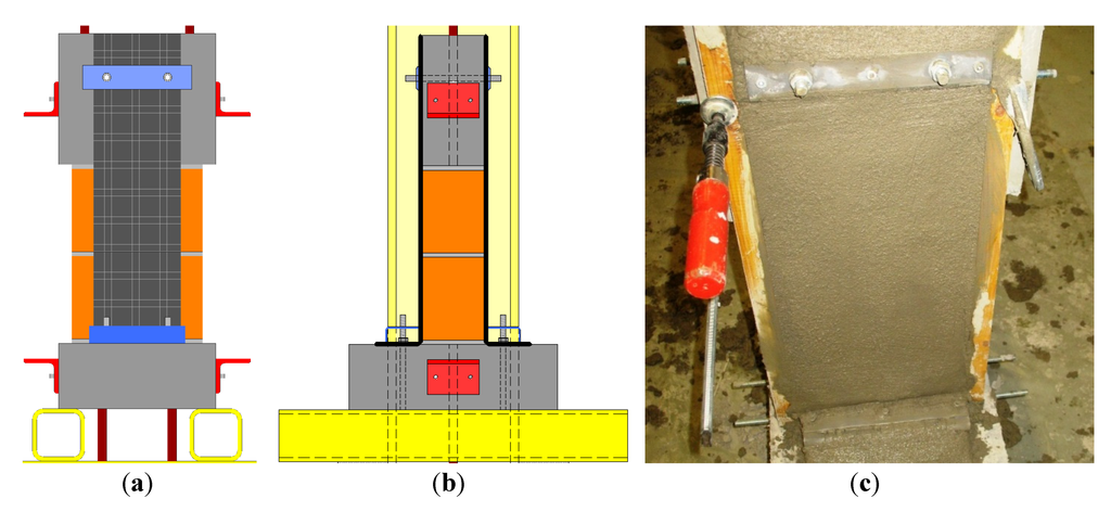
Figure 13.
(a,b) Model of specimen in Series AT-G in view and sectional drawing; and (c) Construction of specimen in Series AT-G.
Figure 13.
(a,b) Model of specimen in Series AT-G in view and sectional drawing; and (c) Construction of specimen in Series AT-G.
5.2. Test Results
5.2.1. Series AT-F
A summary of the test results is given in Table 8. The load-displacement curves of the retrofitted masonry elements in Series AT-F are shown in Figure 14.

Table 8.
Test results of Series AT-F.
| Specimen | Fmax (kN) | Fmax/Ru 1 (−) | σmax (N/mm2) | δ(Fmax) (mm) | ε(Fmax) (%) |
|---|---|---|---|---|---|
| AT-F1 | 30 | 0.27 | 1051 | 4.0 | – |
| AT-F2 | 33 | 0.29 | 1157 | 13.8 | 1.47 |
| AT-F3 | 81 | 0.29 | 1156 | 5.7 | – |
| AT-F4 | 55 | 0.20 | 780 | 10.9 | 1.16 |
| AT-F13 | 41 | 0.15 | 654 | 3.2 | – |
| AT-F14 | 59 | 0.21 | 933 | 4.6 | – |
Note: 1 Ru represents the theoretical ultimate tensile strength.
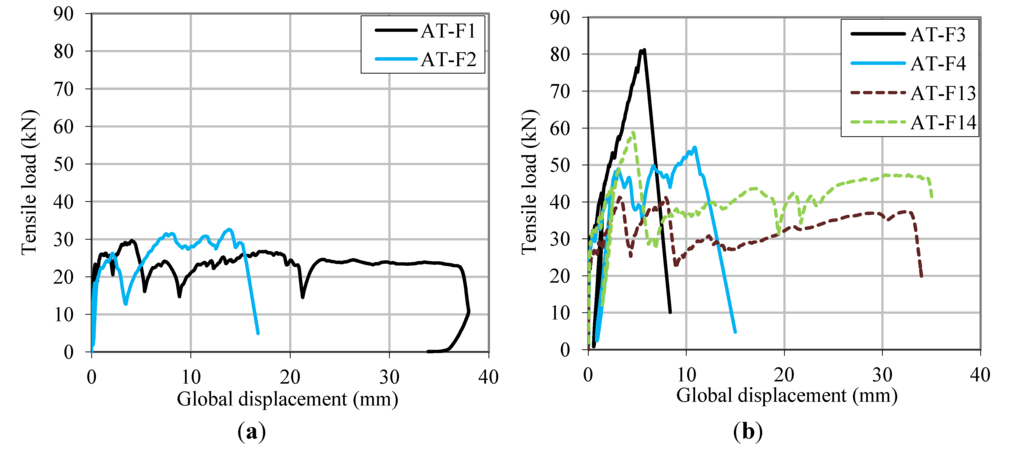
Figure 14.
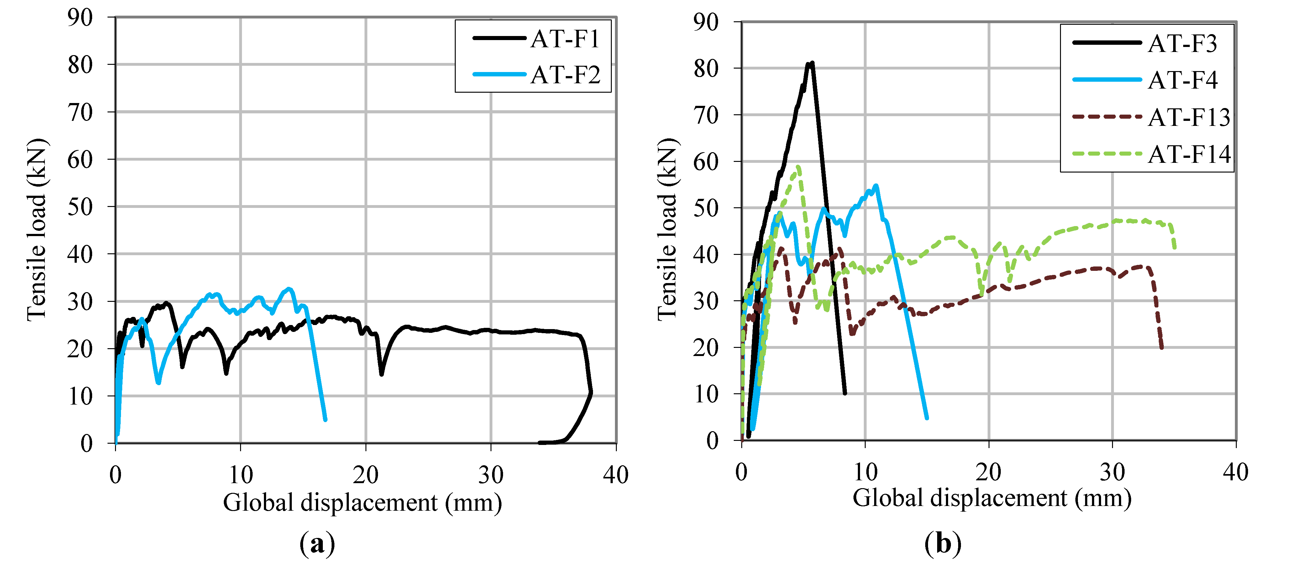
Load-displacement curves. (a) Specimens AT-F1/F2 with mesh L200; and (b) Specimens AT-F3/F4/F13/F14 with mesh L500.
Figure 14.
Load-displacement curves. (a) Specimens AT-F1/F2 with mesh L200; and (b) Specimens AT-F3/F4/F13/F14 with mesh L500.
Two failure patterns were observed:
For test specimens without a fixed carbon mesh, the pull-out strength of the carbon fiber bundles in the spray mortar was critical. Specimens AT-F1 and AT-F2 with the mesh L200 failed at a tensile fiber stress slightly higher than 1000 N/mm2, whereas specimens AT-F13 and AT-14 with the mesh L500 failed at a tensile fiber stress between 650 and 1000 N/mm2. Hence, the maximum anchored fiber stresses were not improved by pressure application. Possibly, the chemical reaction between fibers and spray mortar was reduced by the thinner layer of spray mortar. Furthermore, it is probable that the majority of the applied compression stresses were transferred directly through the spray mortar without affecting the fibers. The test specimens AT-F1/F13/F14 with the newer mesh technology exhibited a “quasi-ductile” behavior at around 80% of the maximum applied load. Test specimen AT-F3 with the older mesh technology, however, abruptly failed when reaching the maximum fiber stress.
For test specimens with fixed and pre-stressed carbon meshes, the tensile stresses are completely transferred from the mesh to the mechanical anchorage. The mechanical anchorage is considerably stiffer than the anchorage through bonding between carbon mesh and spray mortar. Nevertheless, the maximum anchored tensile stress could not be improved in comparison to specimens without mechanical anchorage. In test AT-F4, stress concentrations caused by non-uniform pre-stress conditions were most probably the reason for premature fiber rupture at a very low fiber stress. The pre-stress conditions are, however, difficult to control.
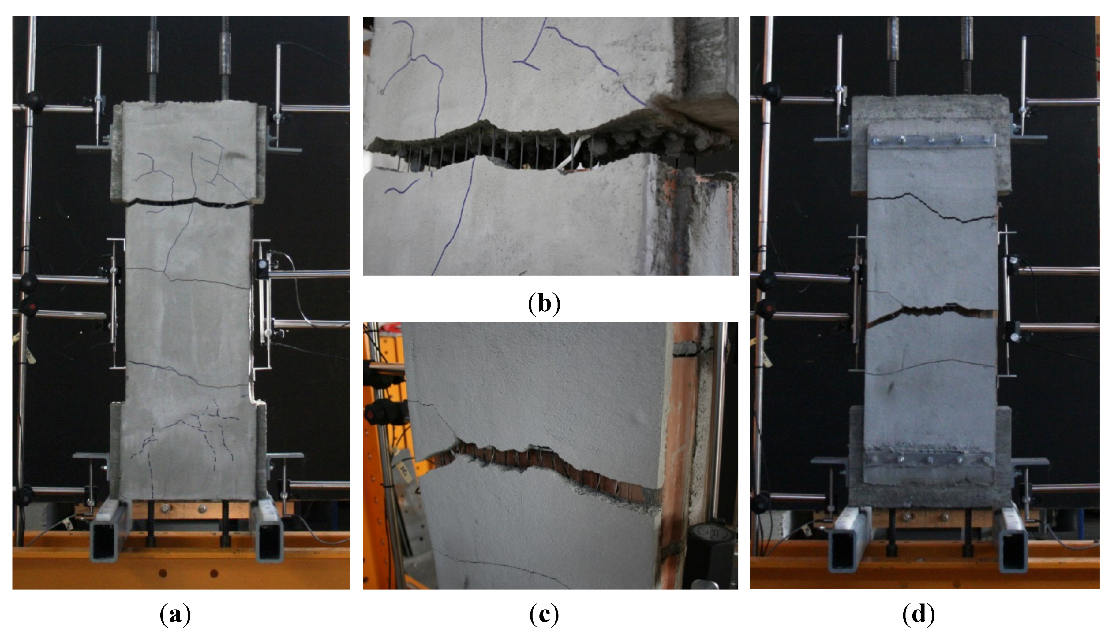
Series AT-F nicely displays how the shear bond transfer between masonry and the studied retrofitting system behaves. Between masonry bricks or between concrete block and masonry brick, shear bond transfer is reduced while axial strain in the fibers is enhanced as the masonry wall “opens” in the mortar layers under tension. Consequently, cracks in the retrofit occur within these “weak” zones (see cracking in test AT-F1 in Figure 15). This bond transfer seems to function in analogy to the “Tension Chord Model” for reinforced concrete [18].
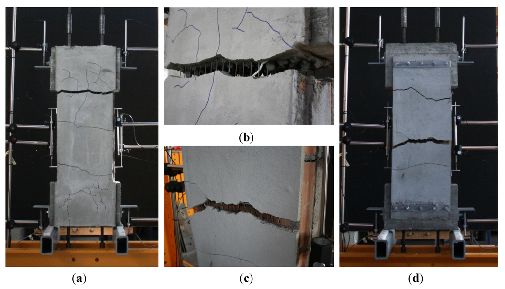
Figure 15.
(a) Cracking in spray mortar in test AT-F1; (b) Failure in test AT-F1; and (c,d) Failure in test AT-F2.
Figure 15.
(a) Cracking in spray mortar in test AT-F1; (b) Failure in test AT-F1; and (c,d) Failure in test AT-F2.
5.2.2. Series AT-G
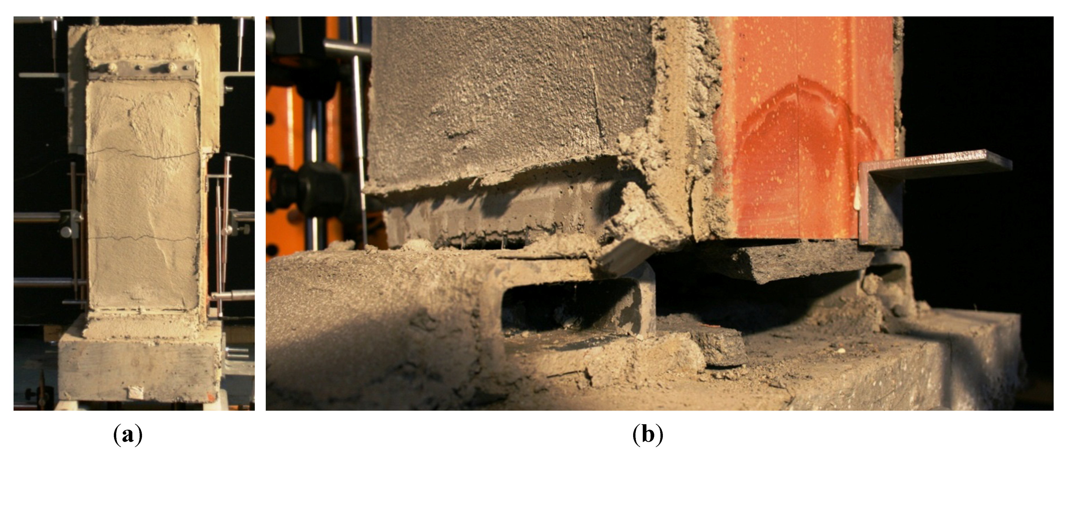
A summary of the test results is given in Table 9. The load-displacement curves of the retrofitted masonry walls in Series AT-G are shown in Figure 16. Specimens with equal characteristics behave very similarly in stiffness and cracking during the first load cycle (up to 600 N/mm2). However, in the second load cycle up to failure, the deformations, particularly, vary widely. Reasons are most probably non-uniform pre-stress conditions and, hence, local stress concentrations, even though the test specimens had been prepared with great diligence. Thus, the reliability of this anchorage system has to be improved in order to allow an application in situ.
Series AT-G showed the same findings in cracking as in Series AT-F (see Figure 17a). Cracks in the retrofit occur around the mortar layers of the masonry walls. Failure always happened in the curvature of the steel profile (see Figure 17b). However, no relevance between curvature radius and maximum load can be established from the test results.

Table 9.
Test results of Series AT-G.
| Specimen | Fmax (kN) | Fmax/Ru 1 (−) | σmax (N/mm2) | δ(Fmax) (mm) | ε(Fmax) (%) |
|---|---|---|---|---|---|
| AT-G1 | 31 | 0.41 | 1,646 | 7.2 | 1.18% |
| AT-G2 | 37 | 0.20 | 794 | 6.7 | 1.10% |
| AT-G3 | 39 | 0.21 | 830 | 3.9 | 0.64% |
| AT-G4 | 36 | 0.19 | 768 | 2.8 | 0.46% |
| AT-G5 | 19 | 0.25 | 996 | 1.6 | 0.26% |
| AT-G6 | 37 | 0.20 | 801 | 5.8 | 0.95% |
Note: 1 Ru represents the theoretical ultimate tensile strength.
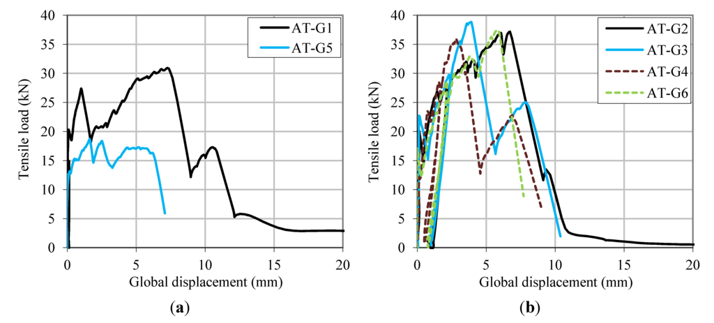
Figure 16.
Load-displacement curves. (a) Specimens AT-G1/G5 with mesh L200; and (b) Specimens AT-G2/G3/G4/G6 with mesh L500.
Figure 16.
Load-displacement curves. (a) Specimens AT-G1/G5 with mesh L200; and (b) Specimens AT-G2/G3/G4/G6 with mesh L500.
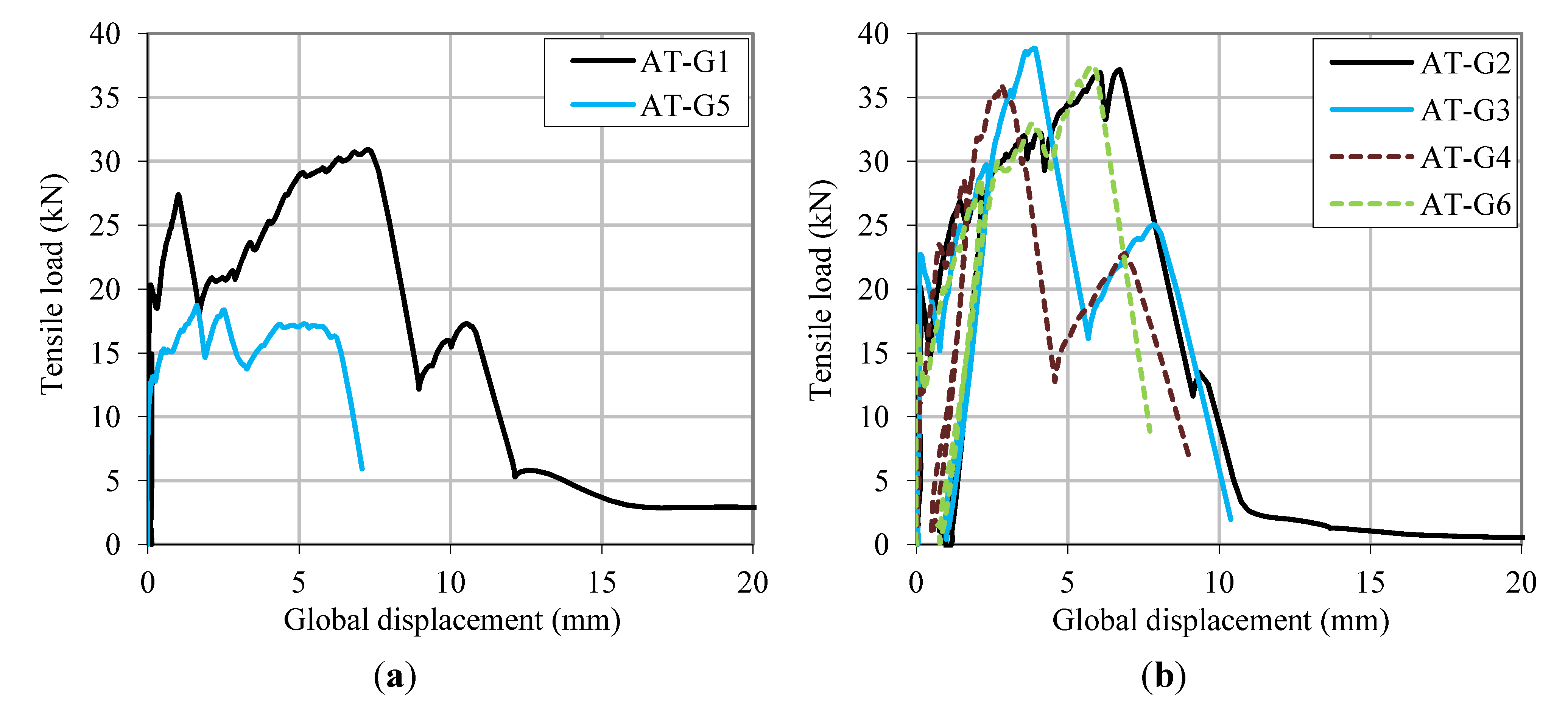
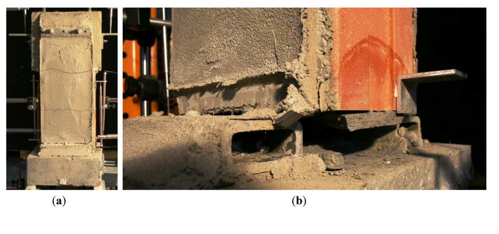
Figure 17.
(a) Cracking in test AT-G5; and (b) Failure in test AT-G5.
Figure 17.
(a) Cracking in test AT-G5; and (b) Failure in test AT-G5.
6. Conclusions
Static-cyclic shear load tests as well as tensile tests on retrofitted masonry walls have been conducted at UAS Fribourg for a first evaluation of the retrofitting system S&P ARMO-System. The static-cyclic shear load tests have shown that masonry walls retrofitted by this retrofitting system demonstrate practically identical behavior as masonry walls retrofitted by bonded CFRP sheets or plates. Hence, they represent an equivalent alternative to these other retrofitting techniques of masonry walls. It should, furthermore, be possible to construct new buildings with “reinforced masonry walls”.
By applying CFRP sheets or carbon meshes as reinforcement to masonry walls, a new inner state of stress is generated. The reinforcement acts as a tension strut, whereas the masonry acts as a compression strut. The analysis of this tension and compression strut creates the possibility to design according to the truss analogy or according to stress fields.
The results of the tensile tests on retrofitted masonry elements revealing the lower performance of commercial mortar as opposed to ARMO-crete w have proven the effectiveness of the latter for embedding the carbon mesh. Only when applying together with the carbon mesh L200 (47 mm2/m), the use of PC based mortar should, however, also be a valid option for new constructions.
A crucial detail for functioning retrofits of masonry walls by means of carbon meshes is the anchorage of the tensile loads in the adjacent concrete slab. Tensile tests on the lighter mesh L200 have shown that mean fiber stresses between 1000 and 1300 N/mm2 can be anchored. The tensile tests on the heavier mesh L500 (117 mm2/m for old technology and 105 mm2/m for new technology) lead to mean fiber stresses between 650 and 1000 N/mm2. These stresses lie above the maximum design recommendation (650 N/mm2). However, especially the mechanical anchorage of the mesh L500 involves uncertainties concerning non-uniform pre-stress conditions and consequential fiber stress concentrations. Therefore, improvements on the mechanical anchorage of the mesh L500 should be pursued in future research projects.
Overall, the various experimental series on masonry walls retrofitted with carbon mesh have brought about very positive results and interesting findings. They confirmed the good applicability of retrofits of masonry walls by means of the carbon meshes embedded in high quality mortar.
Acknowledgments
The presented experiments were conducted within the research project AGP 21,159 “Seismic retrofit of masonry structures”. The authors thank the following institutions, research funds, and companies for funding this project: Federal Office for the Environment (FOEN); Research fund of University of Applied Sciences and Arts, Western Switzerland (HES SO); S&P Clever Reinforcement Company AG, Seewen SZ; Union des Fabricants de Produits en Béton de Suisse Romande; Brick manufacture Morandi Frères AG, Corcelles près Payerne; Brick manufacture Freiburg & Lausanne AG, Düdingen; Fixit AG, Bex (all Switzerland).
Conflicts of Interest
The authors declare no conflict of interest.
References
- SIA. Swisscodes for engineers; Swiss Society of Engineers and Architects (SIA): Zurich, Switzerland, 2003. [Google Scholar]
- Wenk, T. Einführung in die Erdbebenbemessung mit den neuen Tragwerksnormen; Swiss Society for Earthquake Engineering and Structural Dynamics: Zürich, Switzerland, 2004. [Google Scholar]
- S&P Clever Reinforcement Company Seismic References/Pictures. Available online: http://www.reinforcement.ch/products/frp-tragwerkverstaerkung/anwendungsbereiche-referenzen/ (accessed on 30 November 2013).
- Schwegler, G. Verstärken von Mauerwerk mit Faserverbundwerkstoffen. Dissertation, Eidgenössische Technische Hochschule Zürich (ETHZ): Zürich, Switzerland, 1994. [Google Scholar]
- Triantafillou, T. Composites: A new possibility for the shear strengthening of concrete, masonry and wood. Compos. Sci. Technol. 1998, 3538, 1285–1295. [Google Scholar] [CrossRef]
- ElGawady, M.; Lestuzzi, P.; Badoux, M. Dynamic Tests on URM Walls before and after Upgrading with Composites; École Polytechnique Fédérale de Lausanne (EPFL): Lausanne, Switzerland, 2003. [Google Scholar]
- Prota, A.; Manfredi, G.; Nardone, F. Assessment of design formulas for in-plane FRP strengthening of masonry walls. J. Compos. Constr. 2008, 12, 643–649. [Google Scholar] [CrossRef]
- Zhuge, Y. FRP-retrofitted URM walls under in-plane shear: Review and assessment of available models. J. Compos. Constr. 2010, 14, 743–753. [Google Scholar] [CrossRef]
- Suter, R.; Broye, A.; Grisanti, M. Essais de cisaillement de murs en maconnerie renforces, série expérimentale pluriels MR-A, MR-B, MR-C; University of Applied Sciences (UAS): Fribourg, Switzerland, 2010. [Google Scholar]
- Bischof, P. Mechanical Anchorage of CFRP Sheets Retrofitting Masonry Walls. (Master Thesis), Swiss Federal Institute of Technology Zurich (ETHZ), Zurich, Switzerland, 2011. [Google Scholar]
- Bischof, P.; Suter, R.; Chatzi, E.; Lestuzzi, P. Mechanical Anchorage of CFRP Sheets Retrofitting Masonry Walls. In Proceedings of Second Middle East Conference on Smart Monitoring, Assessment and Rehabilitation of Civil Structures (SMAR), Istanbul, Turkey, 9–11 September 2013.
- S&P Clever Reinforcement Company. Technical Data Sheet: S&P ARMO-System. 2013. Available online: http://www.reinforcement.ch/products/frp-fiber-reinforced-polymer/technical-data-sheets/?L=1 (accessed on 30 November 2013).
- Suter, R.; Broye, A. Statisch zyklische Versuche zum Erdbebenverhalten von Mauerwerks-wänden. Erdbeben und Mauerwerk (SIA-Dokumentation 0231). 2009, pp. 51–58. Available online: http://www.baufachinformation.de/literatur/2011019020243 (accessed on 30 November 2013).
- Parisi, F.; Lignola, G.P.; Augenti, N.; Prota, A.; Manfredi, G. Rocking response assessment of in-plane laterally-loaded masonry walls with openings. Eng. Struct. 2013, 56, 1234–1248. [Google Scholar] [CrossRef]
- Guide for the Design and Construction of Externally Bonded FRP Systems for Strengthening URM Structures; American Concrete Institute (ACI): Farmington Hills, MI, USA, 2008.
- Guide for the design and construction of externally bonded FRP systems for strengthening existing structures; CNR (National Research Committee)—Advisory Committee on Technical Recommendations for Construction: Rome, Italy, 2004.
- Suter, R.; Jungo, D. Vorgespannte CFK-Lamellen zur Verstärkung von Bauwerken. Beton-und Stahlbetonbau 2011, 96, 350–358. [Google Scholar] [CrossRef]
- Marti, P.; Alvarez, M.; Kaufmann, W.; Sigrist, V. Tension chord model for structural concrete. Struct. Eng. Int. 1998, 8, 287–298. [Google Scholar] [CrossRef]
© 2014 by the authors; licensee MDPI, Basel, Switzerland. This article is an open access article distributed under the terms and conditions of the Creative Commons Attribution license (http://creativecommons.org/licenses/by/3.0/).
