1. Introduction
In the last two decades, fiber reinforced polymer (FRP) materials have found their place among traditional reinforcement and stabilization methods for masonry structures [
1]. Strengthening with high-strength carbon fibers belongs to novel, partially non-invasive and reversible progressive methods based on limiting the appearance and development of tensile cracks resulting from horizontal tensile stresses caused by the contraction and mutual interaction of masonry components with different displacement properties. These are, above all, applications for strengthening structures against bending, tension, and shear and, to a lesser extent, in increasing the load-bearing capacity by wrapping the load-bearing members (mainly columns and pillars [
2,
3]). FRP materials also play an important role in strengthening structures in terms of seismic safety [
4,
5,
6,
7].
FRP materials offer numerous advantages for strengthening and stabilizing historic, mainly masonry structures, by virtue of their low weight, high effectiveness, and potential reversibility [
8]. To date, the application of FRP composites in the restoration of historic and heritage buildings has been primarily focused on stabilizing vertical load-bearing and vaulted structures to resist the effects of horizontal loads due to induced and natural seismicity [
9,
10].
Research into the reinforcement of masonry structures with FRP materials has only in recent years been aimed at increasing the load-bearing capacity of vertical structures (columns and pillars) by wrapping [
11,
12]. The bulk of research addresses brick masonry [
11,
13], with only a few research studies taking interest in stone masonry as well [
14,
15,
16,
17,
18].
The bond strength between the reinforcing composite layer and the strengthened masonry is the key parameter significantly influencing the resultant effectiveness of the strengthening of masonry structures with FRP materials [
19,
20]. This issue has been the subject of extensive experimental [
21,
22] and theoretical research [
23,
24] during the last few years. Some research studies have been focused on the effect of the binder (mortar) on the resultant bond strength between the FRP material and the masonry substrate [
25,
26,
27], the design of new and suitable theoretical models describing the behavior of FRP materials in terms of their adhesion to the substrate [
28], or on the experimental and theoretical investigation of using new, flexible binders for gluing externally bonded FRP reinforcement [
29].
2. Numerical Analysis and Experimental Verification of Failure Mechanisms in Compressed Masonry Columns
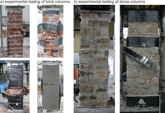
The experimental research was performed on test pieces of brick masonry with dimensions (width × thickness × height) of approximately 286–290 mm × 286–290 mm × 940–1020 mm and stone masonry with dimensions of approximately 530–550 mm × 530–560 mm × 1730–1770 mm with cement mortar as a binder (
Figure 1). The test pieces included reference masonry columns without any FRP application, fabricated as “unreinforced”,
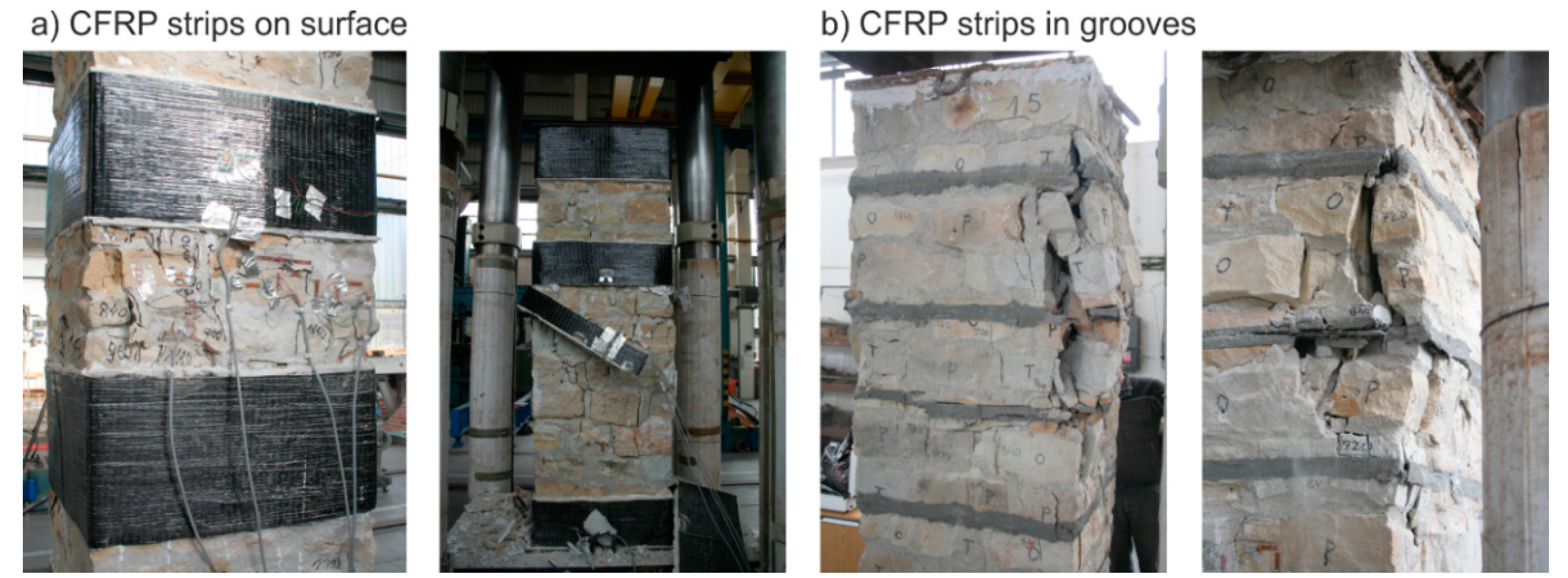
i.e., without passive wrapping of an FRP fabric-based composite, masonry columns “reinforced” with non-pre-stressed FRP-based composite strips applied to their surface with an adhesive bridge of either epoxy resin or a special polymer-modified cement mixture, or reinforced by overall wrapping, and masonry columns reinforced with FRP-based composite strips inserted into horizontal grooves cut into the masonry (
Figure 2). An overview of test pieces used is presented in
Table 1 and
Table 2.
The main objective of the experimental research was to verify the effectiveness (strength performance) of different reinforcing methods according to their parameters (height and distance of reinforcing strips, the number and distance of reinforcing lamellae, influence of used materials or technology etc.). Special interest within the experimental research was focused on verifying the effectiveness of additional column reinforcement to tensile crack damage from the initial phase (i.e., vertical tensile cracks passing through 3 to 6 rows of masonry). The reinforcing methods were chosen with the aim of minimizing possible interference into the structure (surface or near-surface application of FRP materials).
The columns were reinforced by wrapping them in non-pre-stressed strips of high-strength carbon fiber fabric (Tyfo
® SCH-41 fabric) glued onto the reinforced columns with Tyfo
® S thixotropic two-component epoxy resin (FRP system), or by non-pre-stressed strips of mesh made of high-strength carbon fiber Ruredil X Mesh C10 and inorganic stabilized cement matrix M25 (FRCM system). The material characteristics of these carbon fabrics, epoxy adhesive and cement matrix are presented in
Table 3 and
Table 4. The composite strips were 75 or 150 mm in height and were placed at 3 or 4 levels—at the top and bottom of the column and in the middle (3 levels, axial distance of strips was 450 mm) or at third distances along the column’s height (4 levels, axial distance of strips was 300 mm). Another case of reinforcement was overall wrapping of the column in a non- pre-stressed fabric. In this case, a continuous piece of fabric (Tyfo
® SCH-41 fabric) was placed over the whole height of the column (glued by Tyfo
® S epoxy resin). In the final case of reinforcement, on-site pre-laminated strips (lamellae) were inserted into grooves cut into the masonry (pre-laminated strip width was 40 mm, thickness was 5–7 mm and their surface was covered in fine quartz sand for better adhesion. Groove depth was 50–60 mm and thickness was 15–20 mm) filled with polymer cement mortar (Betosan Superfix TH f).
Prior to the application of reinforcing fabrics, the surface of the reinforced columns was levelled and cleaned, stripped of non-cohesive parts, and in the case of stonework columns of coursed rubble masonry and quarried sandstone (irregular sandstone blocks), the surface was levelled where the reinforcing fabric was to be applied. In all cases the column corners were rounded (with a fillet radius of 20 mm).
Reinforcement was performed using a fabric with a unidirectional arrangement of fibers applied in a single layer. Thus, the composite consisted of one layer of fabric and an outer and inner layer of epoxy resin. Both ends of the fabric were connected by an overlap (at least 250 mm in the case of clay brick masonry columns and 400 mm in the case of stone masonry columns). The shear strength of the epoxy resin was relevant for determining the anchoring length so that it would match the corresponding tensile strength of the composite strip. Experimental loading mostly resulted in the fabric’s failure across its surface area, not at the mutual connection of the ends of the fabric forming the overlap.
The test pieces were gradually loaded with incremental loading steps of 60 kN up to their failure. To verify the permanent displacement component, unloading to the basic loading value of 60 kN (10% of the assumed ultimate load of unreinforced columns of brick or stone masonry) was performed after each third loading step. The ultimate load on the columns was identified as a sudden drop in loading accompanied by a loss in the ability of the loaded member to transfer compressive loads as well as the destruction and disintegration of the column masonry. The testing device required the loading process to be controlled by force, thus the post peak phase of the column’s behavior could not be captured.
The masonry displacement and strain values during loading were monitored by means of linear displacement gauges (LVDT) and resistance strain gauges (see
Figure 1). To avoid undesirable distortion of stress values obtained from the strain gauges, the minimum thickness of epoxy resin at the location of mounted strain gauges was strictly monitored. The displacement gauges were removed before reaching the ultimate load (in the last loading step) due to the possibility of their destruction. Partial results of the experimental research assessment are presented in
Table 5 and
Table 6, and graphically displayed in
Figure 3,
Figure 4,
Figure 5,
Figure 6,
Figure 7 and
Figure 8. Examples of characteristic masonry column failures at reaching the ultimate load are shown in
Figure 9 and
Figure 10.
The theoretical value of a column’s load bearing capacity was, in the case of unreinforced columns, identified pursuant to ČSN EN 1996 1-1 [
30]:
where Φ
i,m is the reduction factor at the top (bottom) or in the middle of the column reflecting slenderness end eccentricity [-],
fd is the design compressive strength of masonry [kPa], and
Am is the loaded horizontal gross cross-sectional area [m
2].
where
fk is the characteristic compressive strength of masonry [kPa] according to the values for compressive strength of masonry units (
fb) and mortar (
fm), γ
m is the partial factor for masonry material [-], including mortar execution, moisture content, uncertainties in geometry, and overall degradation pursuant to ISO 13822:2010 [
33].
At the top or bottom of the column
where
ei is the load eccentricity at the top or bottom [m], taking into account also the eccentricity (if any) resulting from horizontal loads (
ehe) and the initial eccentricity (
einit) based on the effective height of the column (
hef/450), and
t is the thickness of the column (dimension in the appropriate direction) [m].
In the middle of the column height
where
where
where
emk is the eccentricity in the middle height of the column [m],
ehm is the eccentricity at mid-height resulting from horizontal loads [m],
einit is the initial eccentricity (
hef/450) [m], and
ek is the eccentricity due to creep [m].
In the case of FRP reinforced masonry columns, the theoretical value of load bearing capacity was identified pursuant to CNR-DT 200 R1/2013 [
32]:
where γ
Rd is the partial factor [-] equal to 1.10 for a confined column,
Am is loaded horizontal gross cross-sectional area of confined member [m
2], and
fmcd is the design compressive strength of the FRP confined member.
where
k’ is the non-dimensional coefficient [-],
fmd is the design compressive strength of unconfined masonry [kPa],
f1,eff is the effective confining pressure [kPa], and
α1 is the coefficient [-] equal to 0.5.
where
gm is the masonry mass-density [kg/m
3], and
α2 and
α3 are coefficients equal to 1.
where
kH is the coefficient of horizontal efficiency [-],
kV is the coefficient of vertical efficiency [-], and
f1 is the lateral confining pressure [kPa].
where
tf is the FRP thickness [m],
bf is the FRP strip width [m],
pf is the center-to-center spacing of FRP strips [m],
Ef is the Young modulus of FRP sheet elasticity [kPa], ε
fd,rid is the reduced design value of FRP strain measured at a columns collapse [-], and
b and
h are the column’s cross-sectional dimensions [m].
where
b’ and
h’ are the column’s dimensions reduced by the corner radius (
b − 2
rc).
for continuous confinement k
V is equal to 1
where η
s is the environmental conversion factor [-], ranging between 0.85 to 0.95 for carbon fibers bonded with epoxy resin (internal or external exposure, respectively),
εfk is the ultimate strain of FRP sheets [-], γ
f is the partial factor of FRP sheets [-] (ranging between 1 and 1.50, depending on the limit state and on the failure mode—whether debonding occurs or not), and 0.004 is the conventional strain limit.
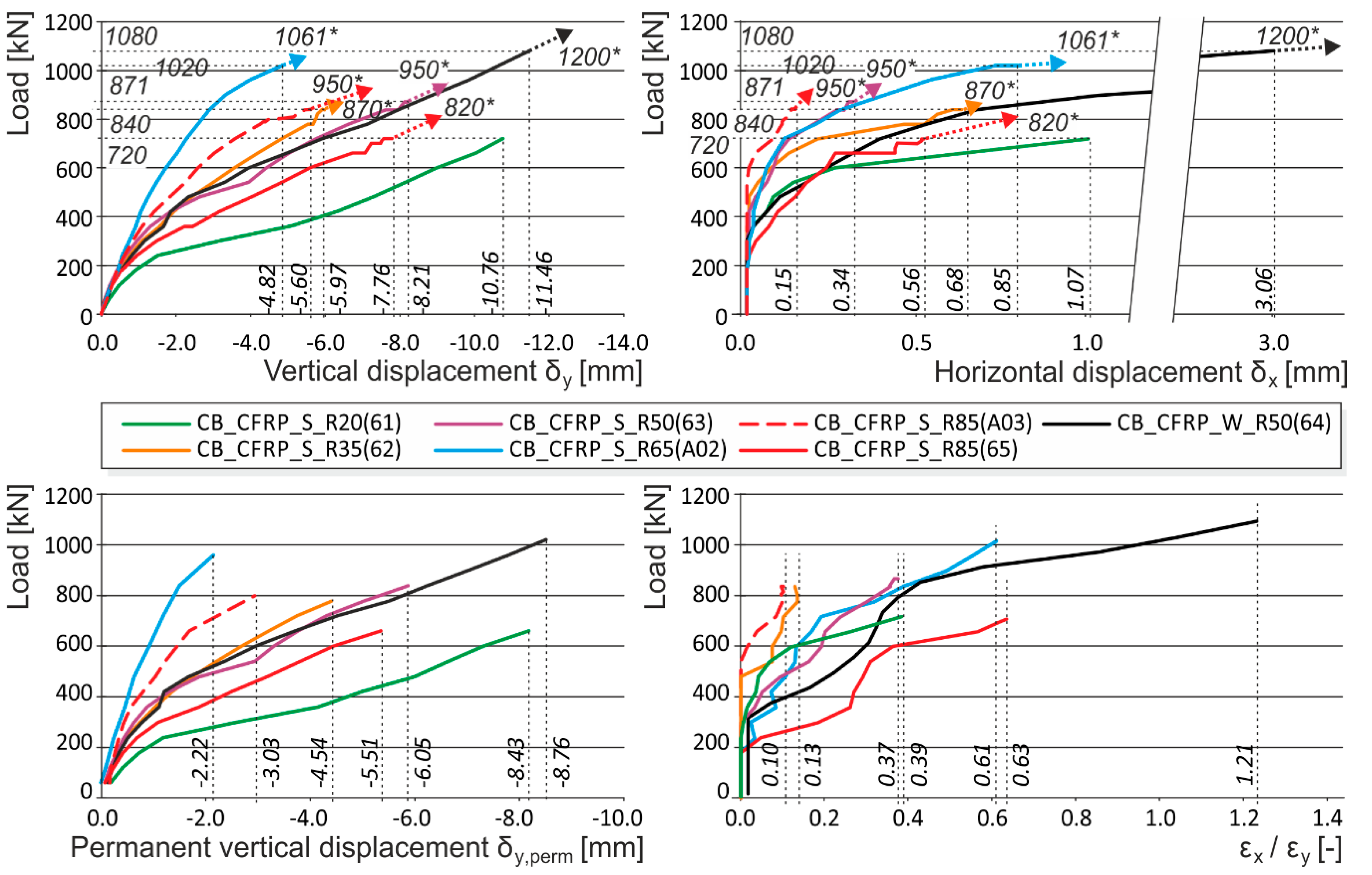
Note: The following load displacement diagrams are presented without the unloading branches (made during the loading process after each third loading step) for better readability. The vertical displacement plotted is a mean value of two measurements from opposite sides of the columns (long measuring bases were used for capturing the overall masonry behavior). Horizontal displacement was measured at the middle height of the column, where the biggest horizontal displacement of the column was expected.
2.1. Failure Mechanism of Brick and Stone Masonry Columns under Concentric Compressive Load
Clarification of brickwork and stonework column failure mechanisms relative to their loading and layout is the basic starting-point for designing masonry structures, their reinforcement and method for stabilization, as well as for deriving accurate formulae for identifying their ultimate loads. Based on analysis of the experimental test results and numerical analyses, the following conclusions about the failure mechanism of compressed masonry columns under concentric load were drawn:
2.2. Failure Mechanism of FRP Reinforced Columns
Based on analyses of the experimental research results, we may say that in the initial failure phase—the appearance of micro and hairline cracks (10
−3 to 10
−1 mm in width)—in agreement with the “masonry–composite” interaction pattern and the relatively low tensile strength of ceramic or natural masonry units and other influences, the effect of a non-pre-stressed wrapping composite is very low (
Figure 13). It is only after the appearance of cracks (in the order of 10
−1 mm or bigger) under higher loading levels that the favorable effect of passive wrapping of column masonry applies more intensely.
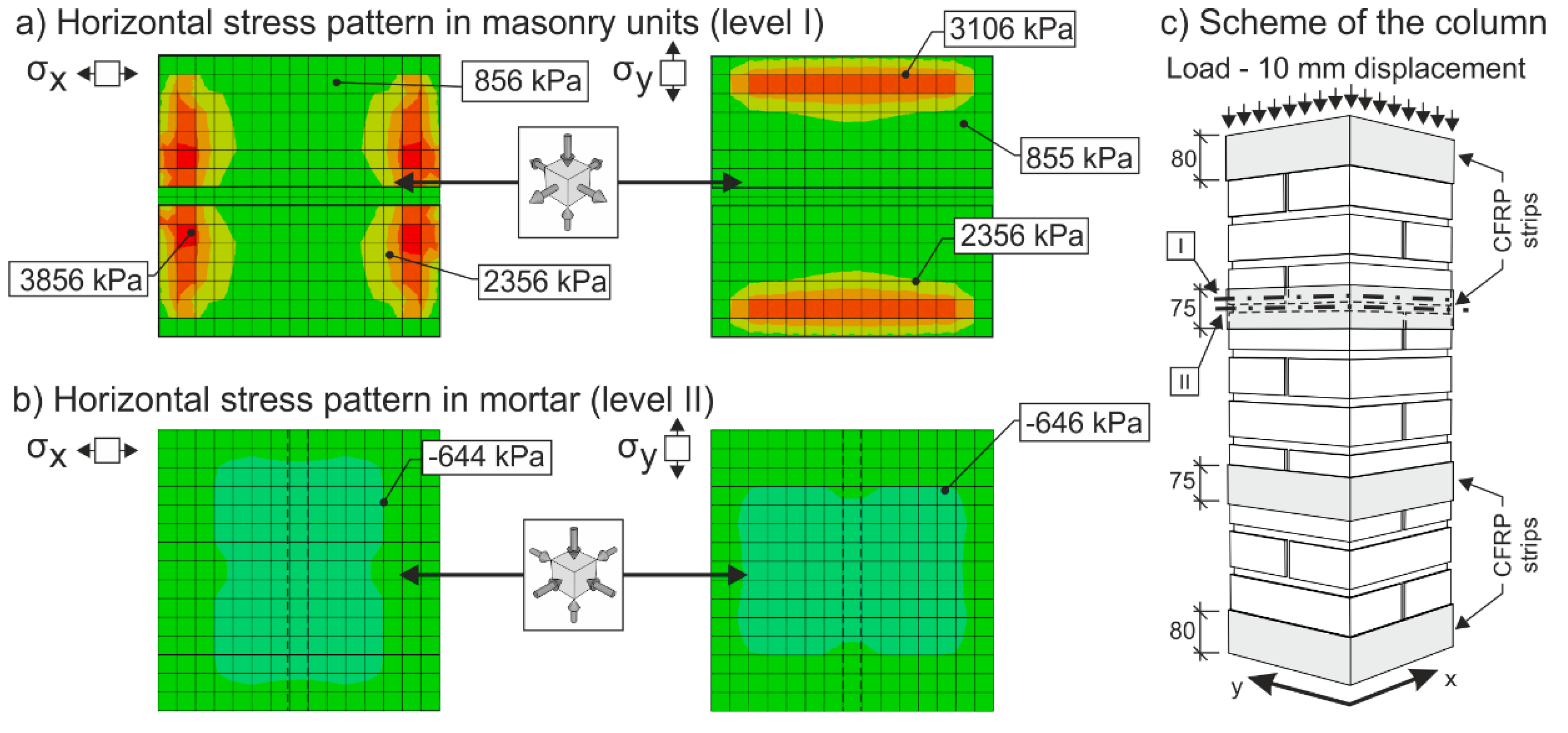
In the case of masonry columns weakly (“insufficiently”) reinforced with partial non-pre-stressed fabric-based composite wrapping strips, the gradual propagation and development process of tensile and shear cracks in the column masonry (phase I) is accompanied by a gradual growth in tensile stresses in this composite due to the effect of “expanding” masonry. Horizontal transverse displacement of masonry is caused by transverse stresses due to the effect of masonry contraction and the effect of mutual interaction between masonry units and the bed joint filler. Despite the growing horizontal and vertical displacements δ
x and δ
y, the masonry column is still able to transfer the growing compressive load due to its reinforcement (stabilization) with discrete passive wrapping in a composite that takes up part of the tensile stresses (
Figure 14 and
Figure 15).
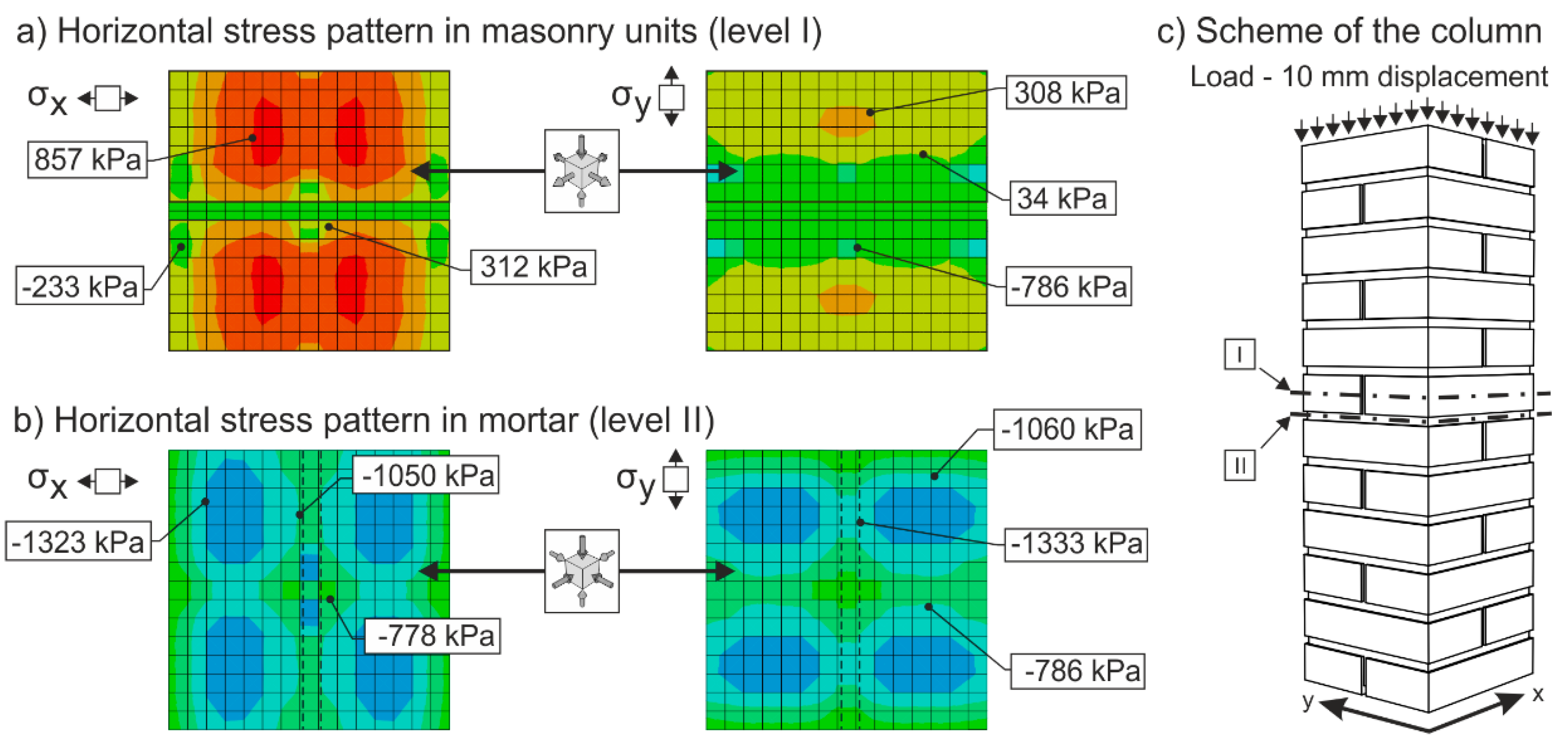
Figure 14 and
Figure 15 represent the results of an Abaqus [
34] linear FEM analysis. Masonry was modelled as two separate materials—bricks (
Ebricks = 2500 MPa, η
bricks = 0.2) and mortar (
Emortar = 500 MPa, η
mortar = 0.15)—with solid three-dimensional hexahedral finite elements (8-node trilinear brick—C3D8R), and reinforcing FRP strips (
Emortar = 140000 MPa, η
mortar = 0.3) modelled with hexahedral shell elements (SC8R). The column was supported at the bottom by prescribed displacement and rotational constraints. The load was applied in the form of imposed vertical displacement at the top of the column.
After tensile crack appearance (in the order of 10
−1 mm and bigger), there is progressive growth in horizontal strains ε
x, the propagation and development of tensile cracks, which become the major agents in the failure of masonry structures under compressive load. The initial value of the ε
x/ε
y ratio in unreinforced columns in the phase preceding the appearance of the first (hairline) cracks lies in the interval of 0.05 to 0.1. When ultimate load in concentric compression is reached, the value of the ε
x/ε
y ratio in unreinforced columns lies in the interval of 0.35 to 0.8, while in the case of columns reinforced with carbon fiber composites lies in the interval of 1.0 to 1.8 (
Figure 16).
In the case of concentrically compressed masonry columns effectively reinforced (strengthened) with a composite based on high-strength fibers and epoxy resin (which takes up part of the transverse tensile forces in the masonry due to the effect of the forced masonry displacement), the failure mode corresponding to phase II applies during the stage when the ultimate load in compression is approached and reached. In this phase of column masonry failure, the compressive strength of the masonry units applies to a greater extent. Attainment of ultimate load is accompanied by the disintegration and crushing of the masonry units and the bed joint filler and, successively, by the total failure (disintegration) of the masonry.
Masonry failure due to the exhaustion of masonry unit compressive strength was observed, for example, in coursed masonry stonework columns with irregular masonry units and thin bed joints (
ca. 12–15 mm), and in brickwork or stonework columns with effective wrapping in carbon fabric composites during the experimental research.
Figure 17 displays the characteristic failure mode of masonry units and the bed joint filler due to tensile cracks and crushing. It is the consequence of efficient interaction between the carbon fabric wrapping and masonry during the phase of active vertical tensile crack development in the column masonry and the partial failure and disintegration of masonry units (phase I and phase II).
In phase II, the adhesive bond in the contact joint between the carbon fabric and masonry usually fails, with the carbon fabric’s reaction to the column masonry’s forced displacement exerted by growing horizontal displacements concentrated in the areas close to the column’s edges. First, perimeter parts of the column loaded with biaxial stress states are damaged—separated by tensile cracks. In the central part of the masonry cross section exposed to stress states by triaxial compression/tension, the masonry completely disintegrates (mainly the masonry units). In this failure mechanism, the compressive strength of individual components (mainly masonry units) primarily applies. This failure mechanism mainly applies in cases with effective wrapping of a masonry column—overall wrapping or wrapping in strips optimally distributed along the column’s length. With increasing distance between and lower height of carbon fabric wrapping strips, as well as lower efficiency of wrapping strips in which lower ultimate load values in concentric compression are reached, the failure mechanism occurring during the first phase (column failure due to vertical tensile cracks) predominantly applies.
2.3. Passive FRP Wrapping Efficiency
The experimental research into brick masonry columns pointed out the option of enhancing the displacement and strain characteristics and the ultimate load (see
Table 5) of masonry columns under concentric compressive load reinforced with a composite of passive wrapping based on high-strength fabrics:
In the case of “optimum” reinforcement of a masonry column with composite strips, i.e., with a distance between strips smaller than or equal to no more than 1.5 times the composite strip height, there was an increase in vertical displacements δy to 247%, horizontal displacements δx to 742%, and ultimate load to 136% compared to the values reached for unreinforced masonry columns.
In the case of overall wrapping of a masonry column in carbon composites, where the failure mechanism (corresponding to phase II) prior to reaching the ultimate load may be assumed, the growth in vertical displacements δy amounted to 161%, horizontal displacements δx 400%, and ultimate load 179%, compared to the values for unreinforced masonry columns.
The experimental research into masonry columns damaged (before reinforcement) by tensile cracks up to (<1.5 mm) in width and extending to
ca. 30%–40% of the column’s height and then additionally reinforced with FRP composites, pointed out the possibility of achieving the comparable mechanical and strain characteristics of identically reinforced undamaged masonry columns (without the initial cracks) through this additional reinforcement (
Figure 18). This is particularly evident in phase I of the columns failure. In this phase, the transverse wrapping of a masonry column in composites with high load-bearing capacity is relevant and the effect of overall column reinforcement is especially dramatic (
Figure 19). This finding agrees with the “composite–masonry” interaction pattern during which the composite is activated with effect only during the phase when tensile cracks develop (10
−1 mm and bigger).
The passive wrapping of column masonry damaged by tensile and shear cracks in non-pre-stressed fabrics made from high-strength fibers represents an efficient stabilization means by preventing further propagation and development of cracks, and securing the structural function of masonry damaged by tensile cracks.
The effectiveness of column masonry passive wrapping in a carbon fiber composite depends on the extent of damage to individual columns and must be assessed separately for each case of masonry failure.
The predominantly positive effect on stress states in triaxial compression of mortar in bed joints in brick masonry after passive wrapping cannot be applied to irregular stone or mixed masonry comprising irregular, roughly dressed masonry blocks with fragments and sharp-edged, undressed, quarry stone masonry units. Here, cracking and masonry damage occur in areas where local stress states with extreme stress values (σ
x, σ
y, τ
xy) arise, e.g., around the masonry layout of irregular, sharp-edged units with a relatively higher modulus of elasticity than the surrounding relatively more yielding binder (
Figure 20). These effects are usually unfavorably manifested, mainly at higher masonry loading values in compression (under loads exceeding 60% of ultimate load). As a consequence, these effects reduce the ultimate strength of stone masonry in compression (
Figure 21).
A special category is represented by compressed masonry columns in which, due to the properties and shape of masonry units, their binder and layout (regular masonry units with identical mechanical properties, thin bed joints with a filler of approximately the same mechanical characteristics as those of the masonry units), no transverse tensile forces that usually compensate the tendency of individual masonry layers towards different transverse displacements under concentric compressive load arise. In these reinforced masonry columns, the transverse displacement of masonry loaded by compressive forces is caused solely by contraction. The effectiveness of passive wrapping of column masonry in these cases is significantly lower compared to coursed masonry with quarry stone blocks (
Figure 22).
2.4. Ultimate Strength of Masonry Reinforced with Composites under Concentric Compressive Load
The analysis of the experimental research results and the failure mechanism of concentrically compressed masonry units indicated that the design procedure of masonry units practiced to-date based solely on the strength of individual masonry components in compression does not correspond to or encompass the interaction between individual masonry components and the masonry failure mechanism under concentric compressive load. The main drawback to calculation formulae may be the fact that standards (ČSN EN 1996-1-1 [
30]) completely ignore or insufficiently consider the tensile strength of masonry components, which is the major agent in the appearance and development of tensile cracks. The full exploitation of tensile strength, masonry, or its individual components may be assumed in cases of coursed masonry with regular masonry units and a bed of low (≤15 mm) joint filler with approximately the same mechanical and displacement properties, and a good bond:
In the case of columns of regular, coursed rubble masonry with dressed stone and thin bed joints reinforced by composite strips, the experimental research demonstrated that the tensile “capacity” of the composite was not efficiently exploited and, due to this, their ultimate load does not significantly increase. In the case of the above masonry, transverse displacements and forced transverse stresses due to the effect of passive wrapping are relatively very low as a consequence of the “mortar bed–masonry unit” lower intensity interaction.
The ultimate load of a reinforced stonework column under concentric compressive load hardly differs from the ultimate load of an unreinforced column (see
Figure 22). The failure occurs by reaching the ultimate displacement and strain of stone masonry in compression δ
ym accompanied by the local failure of masonry in compression—crushing and disintegration of masonry units and the binder. The experimentally measured, relatively low horizontal displacements δ
xm also agree with the failure mechanism of stonework columns with regular, dressed blocks and coursed masonry (phase II). This fact must be considered when calculating the compressive strength of stone masonry reinforced with FRP fabrics, in which the above described failure mechanism under compressive loading applies. Also, the relatively slight effect achieved by wrapping a column in fabrics of high-strength carbon or glass fibers may be objectively assumed.
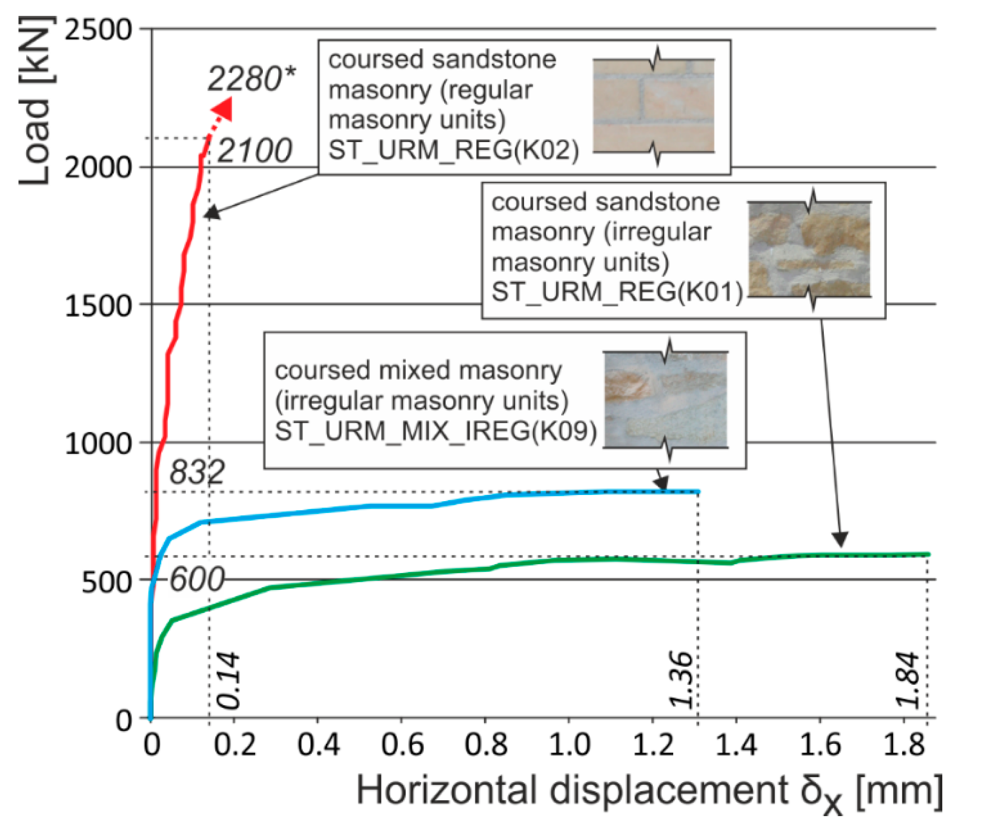
In the case of coursed or irregular stone masonry (column) with undressed or roughly dressed stone blocks and larger bed joints (>20–25 mm) under concentric compressive load, the application of the failure mechanism characterized by the appearance and development of tensile cracks running approximately in the direction of compression trajectories—phase I—may be assumed. It is usually accompanied by the gradual growth in transverse horizontal displacements δ
x in stone column masonry, together with a significant redistribution of compressive loading over the masonry cross section. In the case of an efficient “masonry–fabric (composite)” interaction, the ultimate load of stone masonry in compression dramatically rises compared to the ultimate load of unreinforced stone masonry (
Figure 23) due to the effect of reinforcement by fabrics applied as wrapping bands (EBR) to the masonry or as strips inserted into horizontal joints (NSM).


