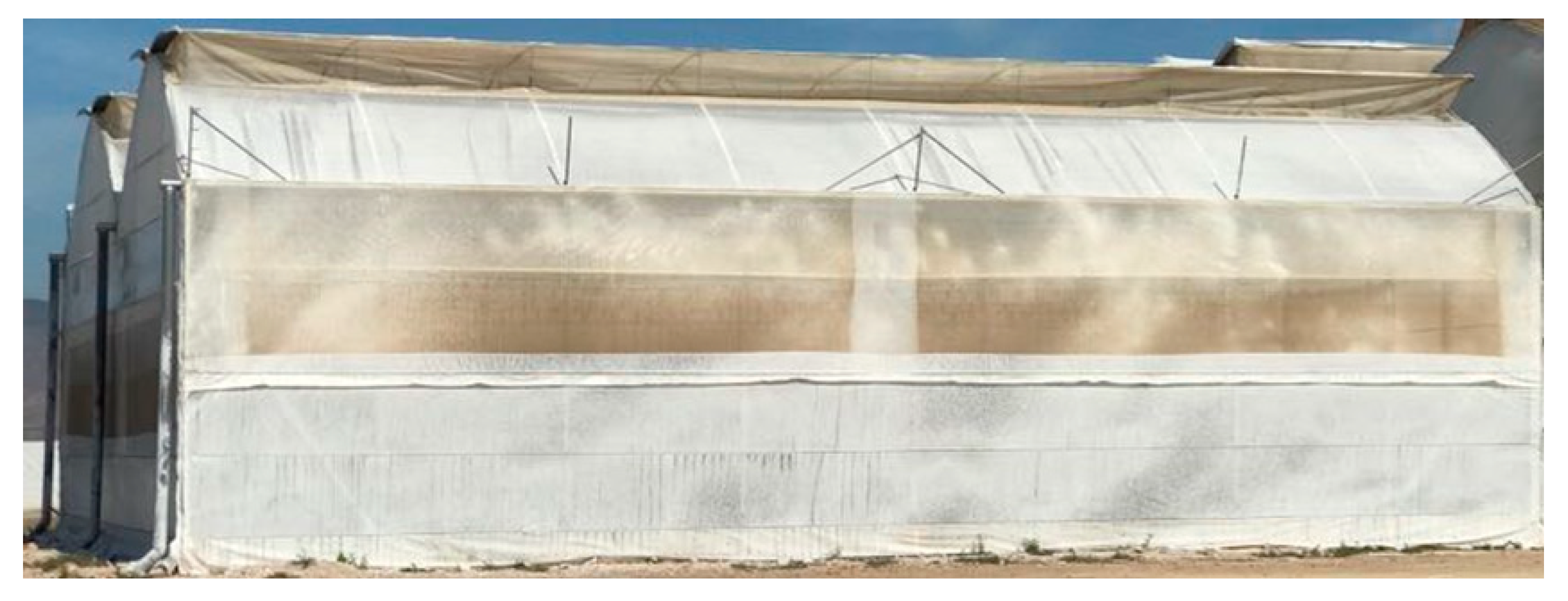
Figure 1.
Greenhouse with fan-pad system.
Figure 1.
Greenhouse with fan-pad system.
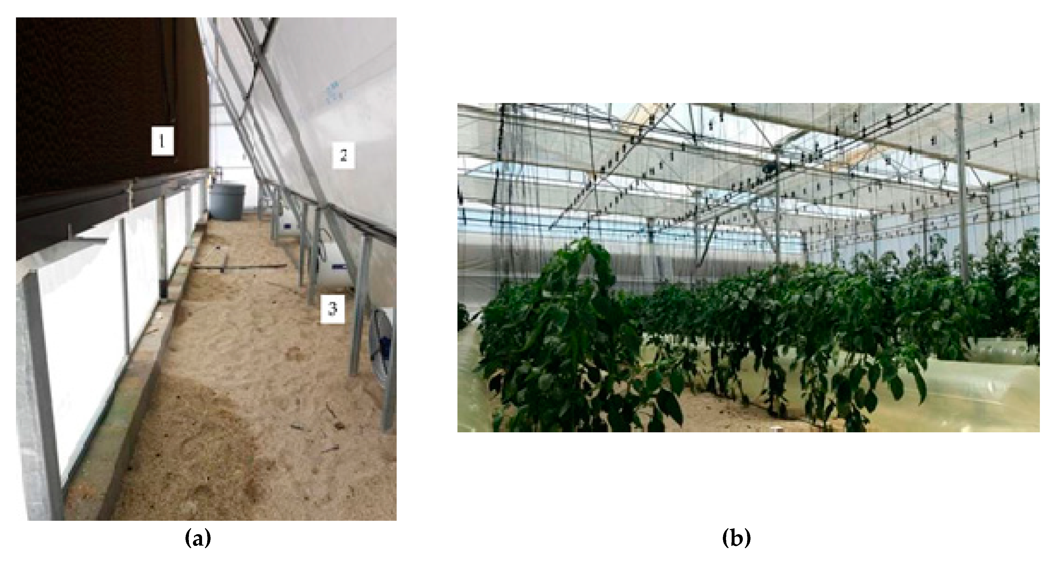
Figure 2.
Greenhouse. (a) Fan-pad system, pre-chamber and extractors. (b) Distribution air ducts.
Figure 2.
Greenhouse. (a) Fan-pad system, pre-chamber and extractors. (b) Distribution air ducts.
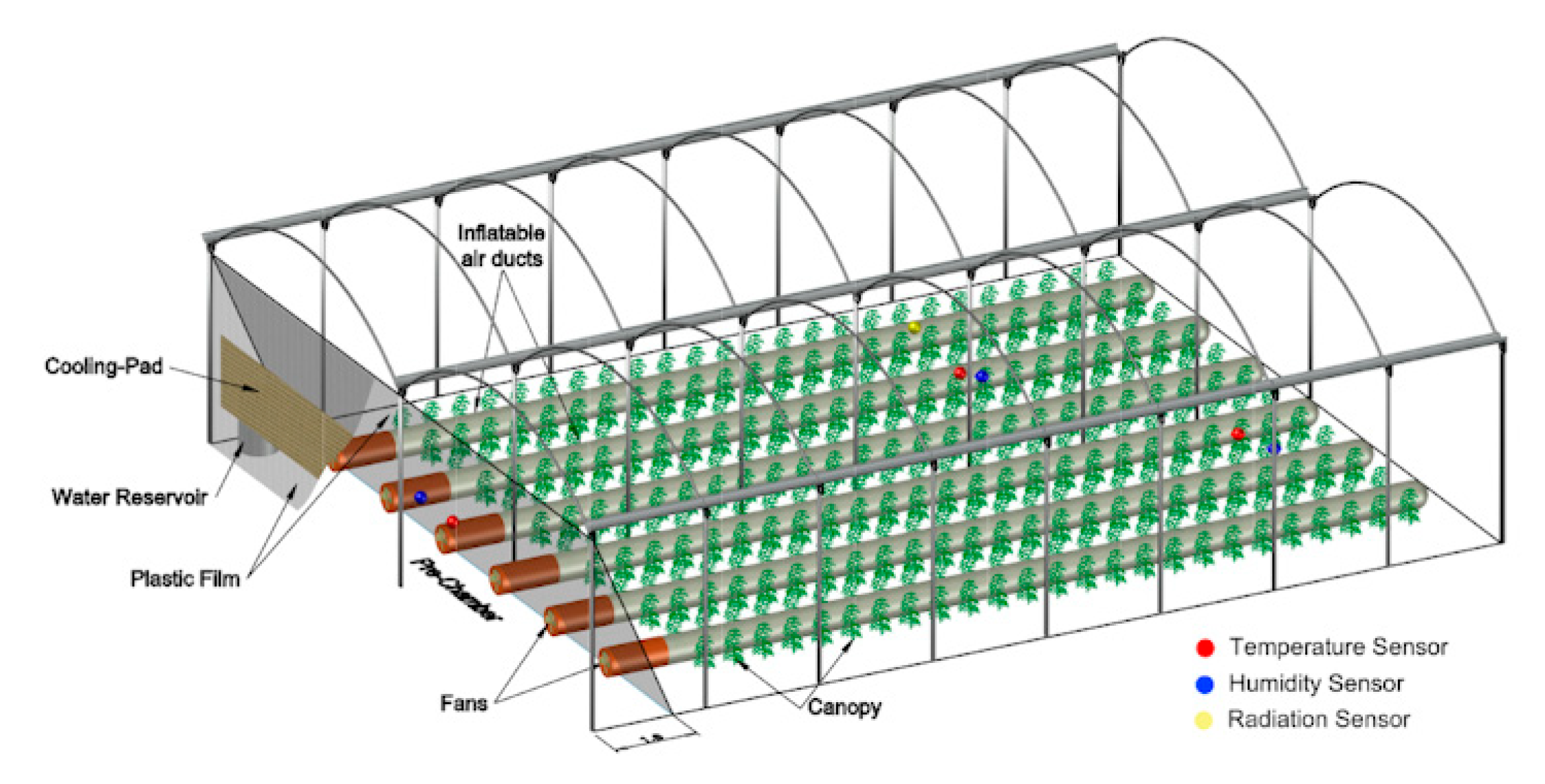
Figure 3.
Diagram of the greenhouse with pre-chamber and inflatable air ducts and the location of the sensors used.
Figure 3.
Diagram of the greenhouse with pre-chamber and inflatable air ducts and the location of the sensors used.
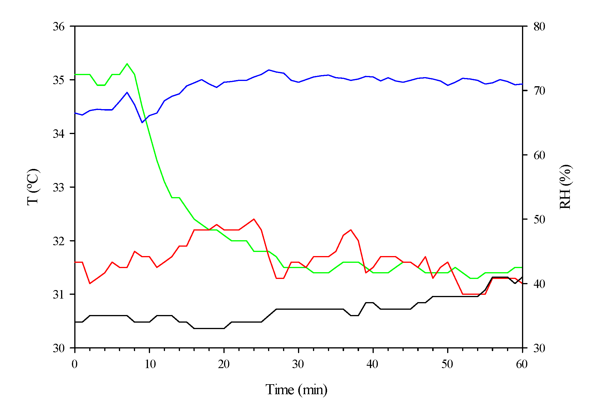
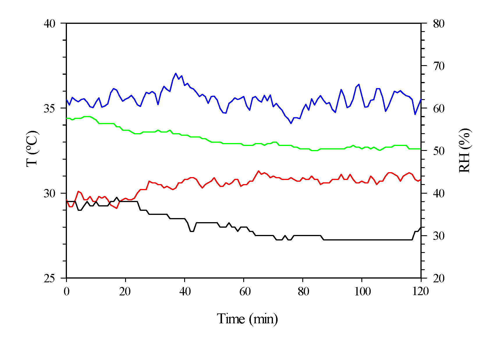
Figure 4.
Temporary evolution of the temperature (T, °C, on the main axis; in the greenhouse, green, and outdoors, red) and relative humidity (RH, %, on the secondary axis; in the greenhouse, blue, and outside, black) during test 1 using the fan-pad system.
Figure 4.
Temporary evolution of the temperature (T, °C, on the main axis; in the greenhouse, green, and outdoors, red) and relative humidity (RH, %, on the secondary axis; in the greenhouse, blue, and outside, black) during test 1 using the fan-pad system.
Figure 5.
State of the air outdoors (red), in the pre-chamber (blue), at the end of the air duct (orange) and in the greenhouse (green) during test 1 when using the fan-pad system. The red arrows represent the evaporative cooling of the air in the pad (which was tilted) and its heating (horizontal) in the pre-chamber.
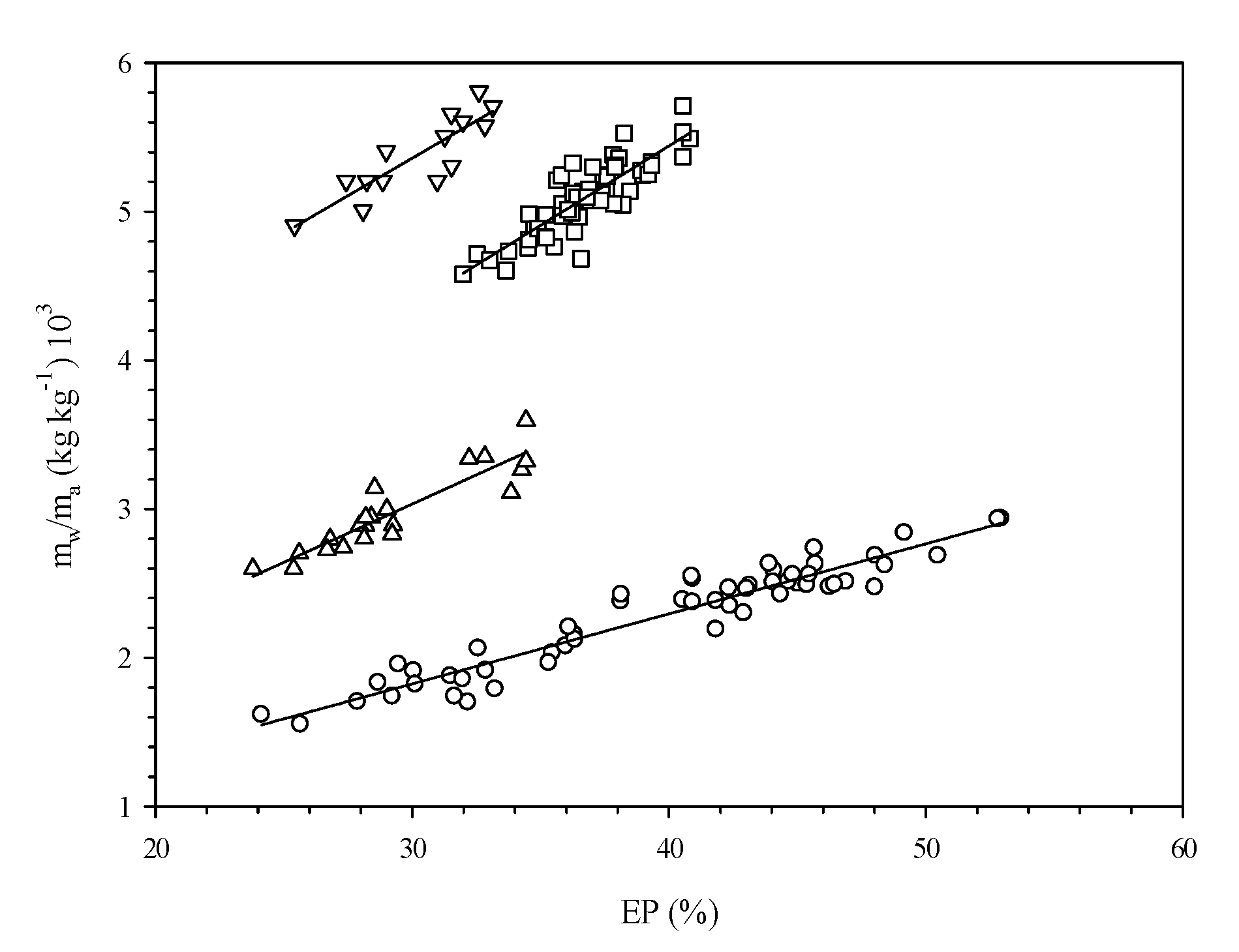
Figure 6.
Relationship between the specific water consumption (mw/ma (kg kg−1) 103) and the EP (%) as a function of the HR value of the outdoor air (75%, ○; 60%, △; 45%, □; and 30%, ▽).
Figure 6.
Relationship between the specific water consumption (mw/ma (kg kg−1) 103) and the EP (%) as a function of the HR value of the outdoor air (75%, ○; 60%, △; 45%, □; and 30%, ▽).
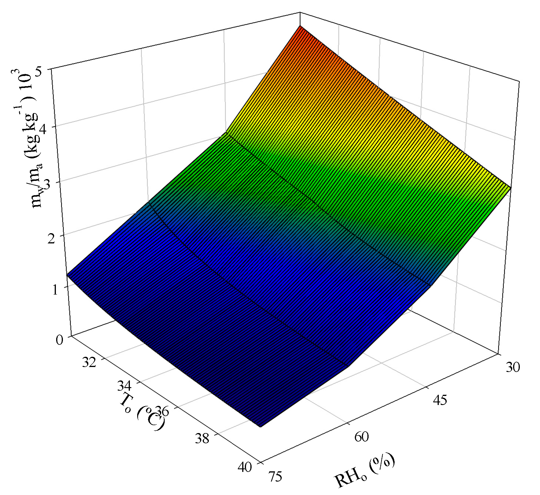
Figure 7.
Evolution of the specific water consumption (mw/ma (kg kg−1) 103) as a function of the exterior temperature (T, °C) and relative humidity (RH, %) values.
Figure 7.
Evolution of the specific water consumption (mw/ma (kg kg−1) 103) as a function of the exterior temperature (T, °C) and relative humidity (RH, %) values.
Figure 8.
Evolution of the air temperature when exiting the pad (Tp, °C) as a function of the exterior temperature (T, °C) and relative humidity (RH, %) values.
Figure 8.
Evolution of the air temperature when exiting the pad (Tp, °C) as a function of the exterior temperature (T, °C) and relative humidity (RH, %) values.
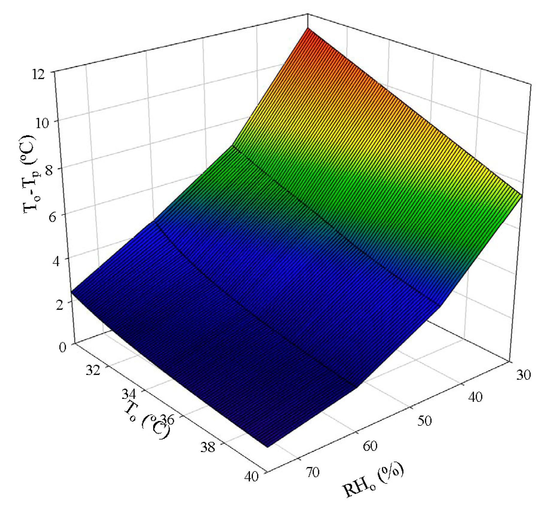
Figure 9.
Evolution of the evaporative air cooling on the pad (To–Tp, °C) as a function of the exterior temperature (T, °C) and relative humidity (RH, %) values.
Figure 9.
Evolution of the evaporative air cooling on the pad (To–Tp, °C) as a function of the exterior temperature (T, °C) and relative humidity (RH, %) values.
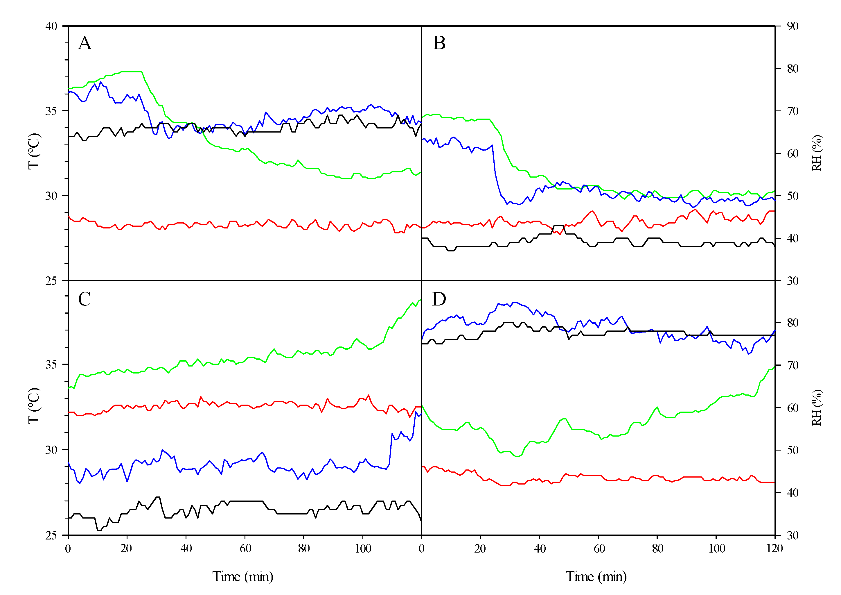
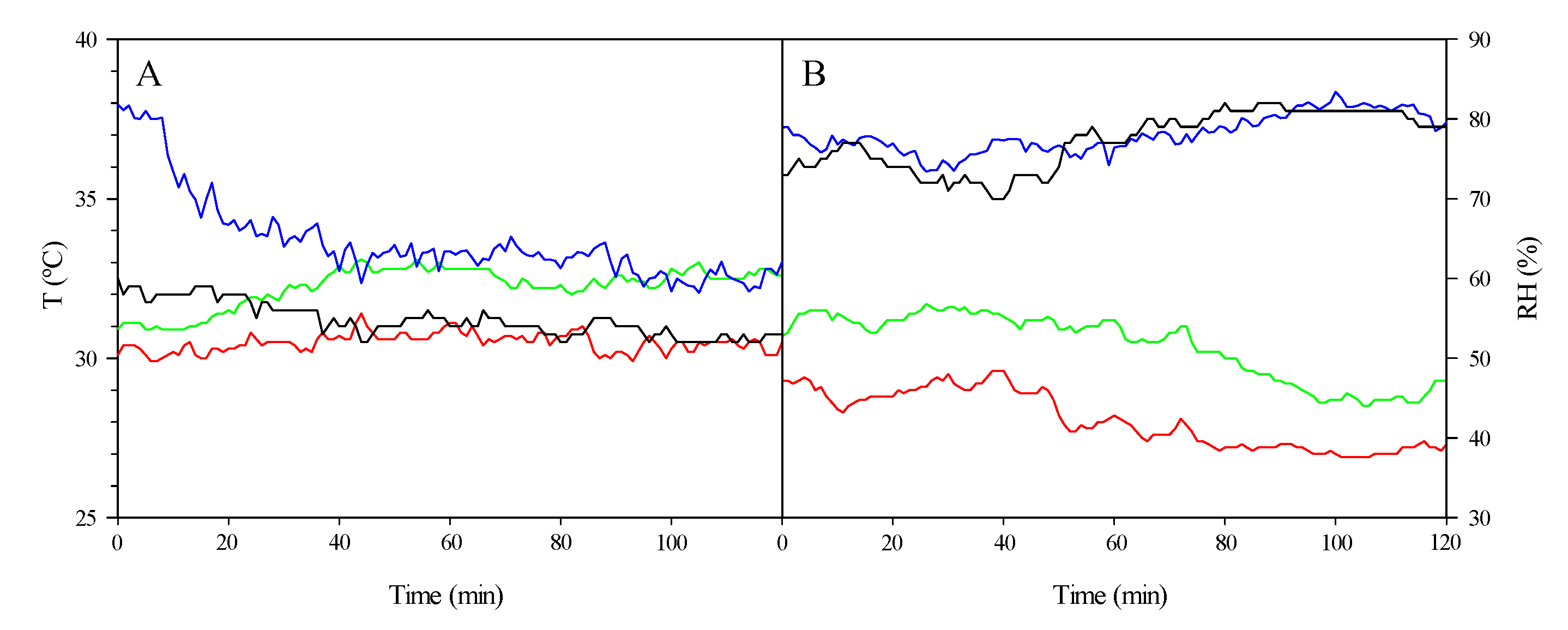
Figure 10.
The temperature (indoor, green, and exterior, red) and relative humidity dynamic (indoor, blue, and exterior, black) for the roof ventilation tests between 13:00 and 15:00. Opening (ΔV > 0; test 2, (A) and test 9, (B)); Closing (ΔV < 0; test 3, (C) and test 10, (D)).
Figure 10.
The temperature (indoor, green, and exterior, red) and relative humidity dynamic (indoor, blue, and exterior, black) for the roof ventilation tests between 13:00 and 15:00. Opening (ΔV > 0; test 2, (A) and test 9, (B)); Closing (ΔV < 0; test 3, (C) and test 10, (D)).
Figure 11.
Temperature dynamics (indoor, green, and outdoor, red) and relative humidity (indoor, blue, and outdoor, black) during shading test 11 between 13:00 and 15:00 h.
Figure 11.
Temperature dynamics (indoor, green, and outdoor, red) and relative humidity (indoor, blue, and outdoor, black) during shading test 11 between 13:00 and 15:00 h.
Figure 12.
Temperature (indoor, green, and outdoor, red) and relative humidity dynamics (indoor, blue, and outdoor, black) during roof and shaded ventilation (V + S) tests between 13:00 and 15:00 h ((A): test 5; (B): test 12).
Figure 12.
Temperature (indoor, green, and outdoor, red) and relative humidity dynamics (indoor, blue, and outdoor, black) during roof and shaded ventilation (V + S) tests between 13:00 and 15:00 h ((A): test 5; (B): test 12).
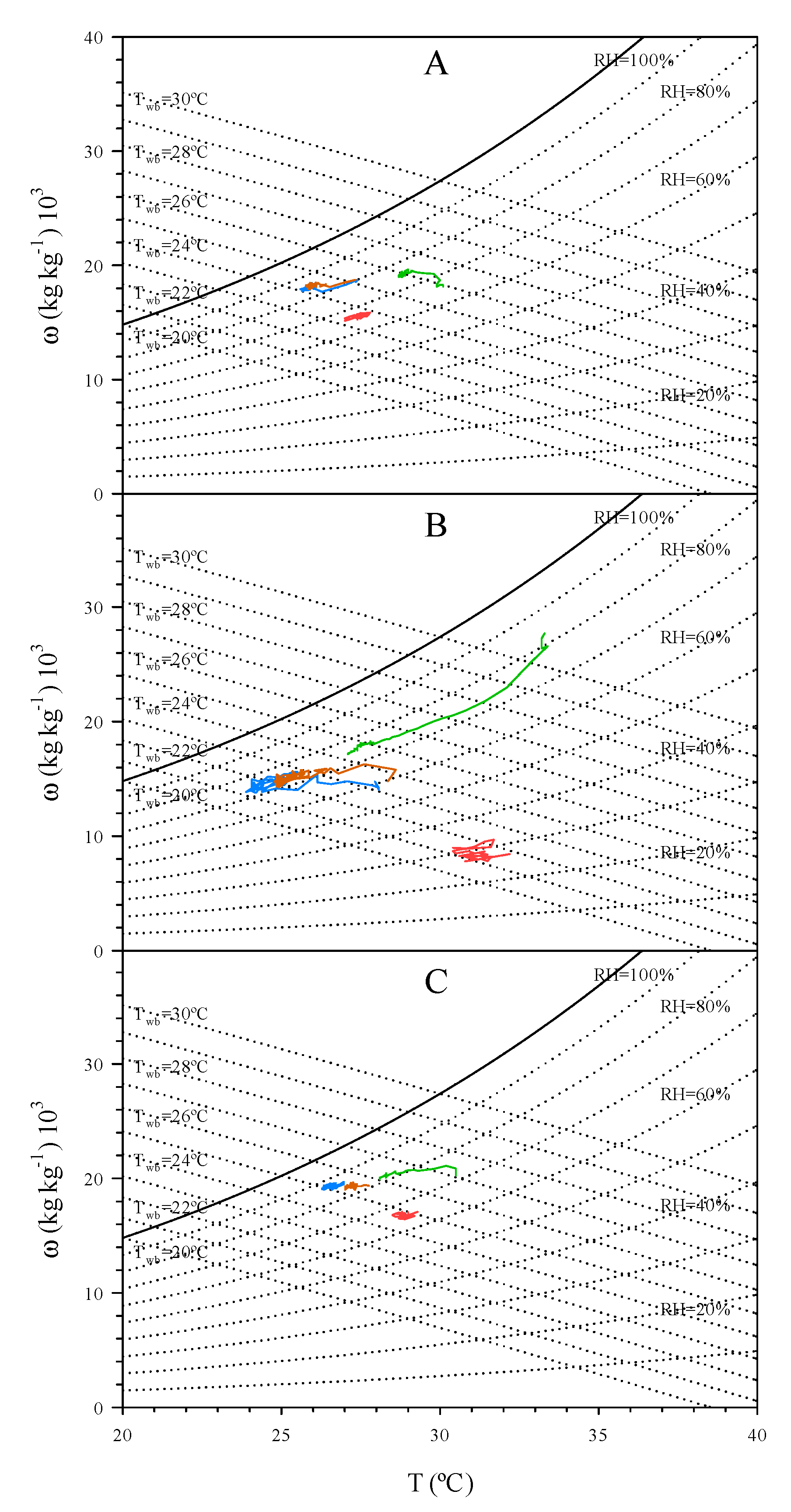
Figure 13.
The state of the air outside (red), in the pre-chamber (blue), at the air duct end (orange) and in the greenhouse (green) during the fan-pad (P) system tests combined with roof ventilation (V) and shading (S) ((A): Test 6, P + V; (B): Test 7, P + S; (C): Test 8, P + V + S).
Figure 13.
The state of the air outside (red), in the pre-chamber (blue), at the air duct end (orange) and in the greenhouse (green) during the fan-pad (P) system tests combined with roof ventilation (V) and shading (S) ((A): Test 6, P + V; (B): Test 7, P + S; (C): Test 8, P + V + S).
Table 1.
Tests performed. The initiation, end, duration and average values for the outdoor climate properties during testing (fan-pad system, S; ventilation, V; shading, S; 0: Off; 1: On).
Table 1.
Tests performed. The initiation, end, duration and average values for the outdoor climate properties during testing (fan-pad system, S; ventilation, V; shading, S; 0: Off; 1: On).
| Test | Date | On/Off (hh:mm) | P | V | S | T (°C) | HR (%) | SR (W m−2) | v (m s−1) | D (Angle, °) |
|---|
| 1 (P) | 21/08 | 13:00/14:00 | 1 | 0 | 0 | 31.7 | 35 | 848 | 4.5 | 88 |
| 2 (V > 0) | 09/08 | 13:00/15:00 | 0 | 1 | 0 | 28.3 | 66 | 904 | 4.4 | 190 |
| 3 (V < 0) | 04/08 | 13:00/15:00 | 0 | 1 | 0 | 32.5 | 36 | 893 | 3.5 | 185 |
| 4 (S) | 12/08 | 13:00/14:00 | 0 | 0 | 1 | 31.0 | 31 | 906 | 6.1 | 99 |
| 5 (V + S) | 03/08 | 13:00/15:00 | 0 | 1 | 1 | 30.5 | 54 | 890 | 3.7 | 190 |
| 6 (P + V) | 23/08 | 13:00/14:00 | 1 | 1 | 0 | 27.4 | 67 | 868 | 3.5 | 198 |
| 7 (P + S) | 22/08 | 13:00/14:00 | 1 | 0 | 1 | 30.4 | 35 | 863 | 4.8 | 177 |
| 8 (P + V + S) | 18/08 | 13:00/14:00 | 1 | 1 | 1 | 28.9 | 66 | 857 | 3.5 | 157 |
| 9 (V > 0) | 11/08 | 13:00/15:00 | 0 | 1 | 0 | 28.5 | 39 | 903 | 5.8 | 119 |
| 10 (V < 0) | 07/08 | 13:00/15:00 | 0 | 1 | 0 | 28.4 | 77 | 568 | 3.8 | 185 |
| 11 (S) | 13/08 | 13:00/14:00 | 0 | 0 | 1 | 30.2 | 35 | 852 | 5.2 | 94 |
| 12 (V + S) | 08/08 | 13:00/15:00 | 0 | 1 | 1 | 28.1 | 77 | 673 | 4.6 | 161 |
| 13 (P + V) | 25/08 | 13:00/14:00 | 1 | 1 | 0 | 28.2 | 66 | 843 | 3.8 | 193 |
| 14 (P + V + S) | 24/08 | 13:00/14:00 | 1 | 1 | 1 | 26.5 | 63 | 869 | 4.5 | 195 |
Table 2.
The average values and standard deviation of the different operating parameters for the fan-pad system in test 1.
Table 2.
The average values and standard deviation of the different operating parameters for the fan-pad system in test 1.
| Operating Parameters | Average Values ± Standard Deviation |
|---|
| To–Tc (°C) | 3.5 ± 0.1 |
| To–Tg (°C) | −0.3 ± 0.2 |
| EFI (%) | 32.1 ± 1.0 |
| EP (%) | 34.7 ± 0.3 |
| qs (kJ kg−1) | 1.9 ± 0.2 |
| ql (kJ kg−1) | 17.0 ± 0.1 |
| mw/ma (kg kg−1) | 0.007 ± 0.000 |
| pw (kg kg−1 h−1 m−2 °C−1) | 0.006 ± 0.000 |
Table 3.
Slope values (A) and the ordinate origin (B) of the linear regressions between the specific water consumption (mw/ma (kg kg−1) 103) and the EP (%) for different outdoor RH values (RHo). The determination coefficient value, R2, and its statistical significance (***, p < 0.0001) are also indicated.
| 103 mw/ma = A·EP + B |
|---|
| RHo, % | A | B | R2 |
|---|
| 75 | 0.047 | 0.407 | 0.89 *** |
| 60 | 0.078 | 0.648 | 0.73 *** |
| 45 | 0.091 | 1.315 | 0.71 *** |
| 30 | 0.103 | 2.336 | 0.79 *** |
Table 4.
Values for the slope (A) and the origin ordinate (B) of the linear regressions between the air temperature at the pad output (Tp, °C) and the outside temperature (To, °C) for different exterior RH values. The determination coefficient value, R2, and its statistical significance (***, p < 0.0001) is also indicated.
| Tp (°C) = A·To (°C) + B |
|---|
| RHo, % | A | B | R2 |
|---|
| 75 | 1.13 | −5.58 | 0.99 *** |
| 60 | 1.23 | −10.83 | 0.99 *** |
| 45 | 1.30 | −15.91 | 0.99 *** |
| 30 | 2.39 | −23.11 | 0.99 *** |
Table 5.
Average values and standard deviation of the different fan-pad system operating parameters. The tests analysed are the fan-pad system (P) together with roof ventilation (P + V, test 6), with shading (P + S, test 7) and with both (P + V + S, test 8).
Table 5.
Average values and standard deviation of the different fan-pad system operating parameters. The tests analysed are the fan-pad system (P) together with roof ventilation (P + V, test 6), with shading (P + S, test 7) and with both (P + V + S, test 8).
| Operating Parameters | P + V | P + S | P + V + S |
|---|
| To–Tc (°C) | −1.4 ± 0.0 | 6.2 ± 0.1 | 1.7 ± 0.0 |
| To–Tg (°C) | −1.6 ± 0.1 | 3.1 ± 0.1 | 0.5 ± 0.0 |
| EFI (%) | 29.2 ± 0.8 | 52.3 ± 0.8 | 34.4 ± 0.5 |
| EP (%) | 34.5 ± 0.4 | 29.9 ± 0.4 | 28.7 ± 0.3 |
| qs (kJ kg−1) | 0.3 ± 0.1 | −3.0 ± 0.2 | −0.4 ± 0.1 |
| ql (kJ kg−1) | 6.6 ± 0.1 | 14.9 ± 0.2 | 6.3 ± 0.1 |
| mw/ma (kg kg−1) | 0.003 ± 0.000 | 0.006 ± 0.000 | 0.003 ± 0.000 |
| pw (kg kg−1 h−1 m−2 °C−1) | 0.006 ± 0.000 | 0.003 ± 0.000 | 0.004 ± 0.000 |

 ,
, 


