Article

Autonomous Robotic System for Pumpkin Harvesting

1
Department of Biosystems Engineering, Faculty of Agriculture and Natural Resources, University of Mohaghegh Ardabili, Ardabil 13131-56199, Iran
2
Laboratory of Vehicle Robotics, Graduate School of Agriculture, Hokkaido University, Sapporo 060-8589, Japan
3
Department of Informatics, J. Selye University, 94505 Komarom, Slovakia
4
Institute of Information Society, University of Public Service, 1083 Budapest, Hungary
5
Institute of Information Engineering, Automation and Mathematics, Slovak University of Technology in Bratislava, 81107 Bratislava, Slovakia
6
John von Neumann Faculty of Informatics, Obuda University, 1034 Budapest, Hungary
*
Authors to whom correspondence should be addressed.
Agronomy 2022, 12(7), 1594; https://doi.org/10.3390/agronomy12071594
Submission received: 23 March 2022 / Revised: 5 May 2022 / Accepted: 6 May 2022 / Published: 30 June 2022

Abstract

:
The present study focused on the development, optimization, and performance evaluation of a harvesting robot for heavyweight agricultural products. The main objective of developing this system is to improve the harvesting process of the mentioned crops. The pumpkin was selected as a heavyweight target crop for this study. The main components of the robot consist of mobile platforms (the main robot tractor and a parallel robot tractor), a manipulation system and its end-effector, and an integrated control unit. The development procedure was divided into four stages: stage I (designed system using Solidworks), stage II (installation of the developed system on a temporary platform), stage III (developed system on an RT-1 (Yanmar EG453)), and stage IV (developed system on an RT-2 (Yanmar YT5113)). Various indicators related to the performance of the robot were evaluated. The accuracy of 5.8 and 4.78 mm in x and y directions and repeatability of 5.11 mm were observed. The harvesting success rate of 87~92%, and damage rate of 5% resulted in the evaluation of the final version. The average cycle time was 35.1 s, 42.6 s, and 43.2 s for stages II, III, and IV, respectively. The performance evaluations showed that the system’s indicators are good enough to harvest big-sized and heavy-weighted crops. Development of the unique and unified system, including a mobile platform, a manipulation system, an end-effector, and an integrated algorithm, completed the targeted harvesting process appropriately. The system can increase the speed and improve the harvesting process because it can work all day long, has a precise robotic manipulation and end-effector, and a programmable controlling system that can work autonomously.

1. Introduction

Improvement of the mechanized food supply systems and self-sufficiency in the agriculture industry are critical challenges [1]. These concerns, along with many others such as limited agricultural farms, climate change, water crisis, labor shortage, farmer income reduction, and culture changes, threaten the output of farm works. These problems with their complexity push scientists to pursue a goal of “producing more food with limited resources”. Artificial intelligence (AI) and agricultural robots (AR) as robotic technology can be a benchmark technology to answer this question. Developing robots for agriculture farms which are unpredictable environments, needs specific consideration. The ARs can have uninterrupted activity. They have multiple programmability. And also they have programmed for various missions.
The development of ARs as an intelligent system has many challenges, such as auto-navigation systems [2], sensor fusion [3], real-time motion detection [4], and multi-robot controlling [5]. The developed ARs in the laboratory of Vehicle Robotics—Hokkaido University (VeBots) started with the development of a path planning system (1997); continued with multi-robot tractors (2017); and reached intelligent harvesting systems (2019). The final RTs can move on all predicted patterns with high safety indexes [6]. The VeBots laboratory same as many other laboratories in the field of ICT, has researched ARs such as path planning [7], vision intelligence [8], on-road and on-field navigation [9], navigation combination with different sensors [10,11], sensor fusion [12], autonomous tractor [13,14,15], turning functions [16,17], steering control [18], multi-robots [19], various platforms [20,21,22,23], and intelligent systems [6,23,24,25,26,27,28,29,30,31,32,33,34,35,36,37,38,39].
This point seems to be a good maturity level for farm robots. Nevertheless, in close consideration, this powerful and intelligent body (robot tractors) has no hands for any flexible operations. So, the intelligent single/multi-robot tractors required a specifically designed robotic actuating/manipulation system as a complementary unit to do more tasks such as precision harvesting, seeding, fertilizing, watering, and weeding. On the other side, the Japanese farmers met labor shortages in pumpkin fields (like other heavyweight crops such as cabbage, melon, and watermelon). Fieldwork exhaustion and disproportionate income have decreased the number of farmers in these fields. In this regard, Roshanianfard and Noguchi [36] have been developing a harvesting robot for the heavyweight crop since 2018 [36]. They developed a robotic manipulation system for this application with a payload and safety factor of 25 Kg, and 2, respectively, and then developed a kinematic and dynamic algorithm [27,33]. After developing and meeting the actual conditions and limitations, the payload and FOS decrease to 15 Kg and 1.5. Then, Roshanianfard et al. (2019) developed an end-effector to harvest pumpkins [29,38]. Finally, the preliminary tests in different aspects were applied [37]. After finishing the development processes, many tests were completed in various conditions. Some modifications were applied to different system parts such as an algorithm, robotic arm, end-effector, and electrical controlling unit. This study will present the finalized performance evaluation of the targeted system in many technical aspects.

2. Materials and Methods

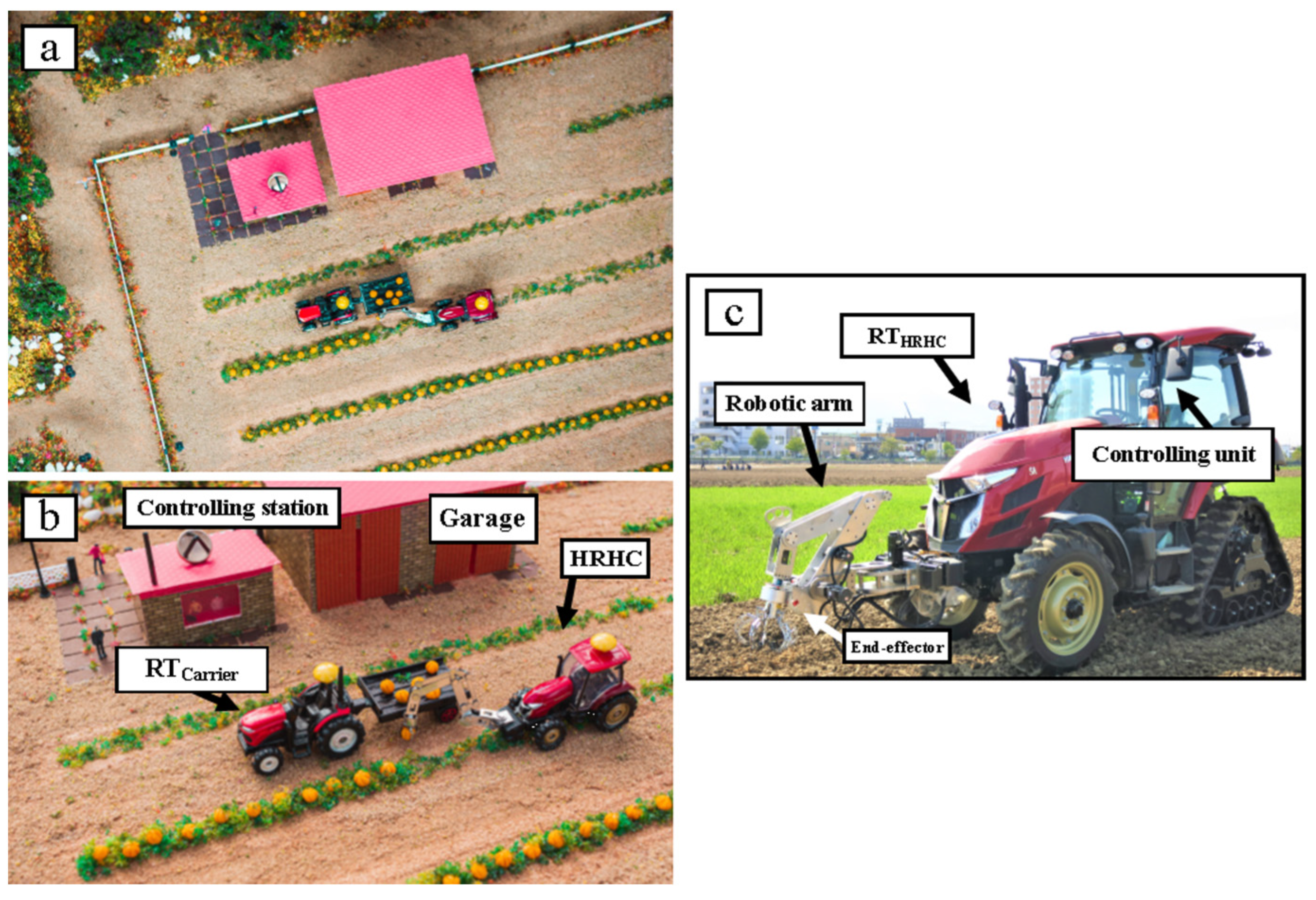
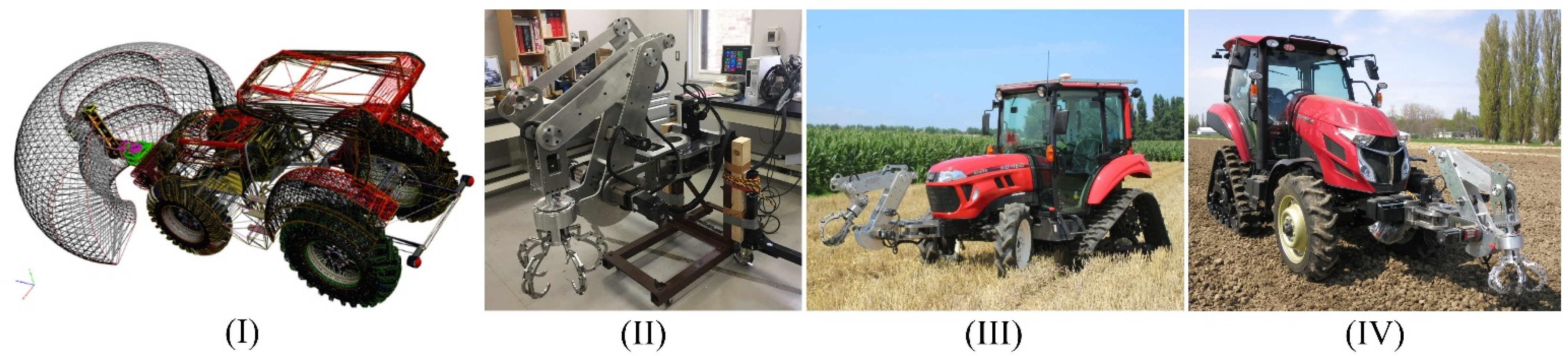
2.1. The Designed and Developed a Robotic System

Many types of robots have limitations in many aspects, such as payload, speed of action, and performance smoothness. Robotic arms move using electrical actuators (as commonly used) that are fast and precise, but they cannot support large torques. Hydraulic and pneumatic actuators can cover this disadvantage, but their complex and heavy components are unsuitable for mobile robots. Studies mainly have focused on light and small agricultural products such as cucumber, tomato, strawberry, and sweet pepper. Heavyweight crops such as melon, pumpkin, cabbage, watermelon, and many others are expensive, favorite, and economical in terms of production. In the Japanese market basket, these crops are expensive products. Based on those reasons, research on these products and developing a robotic harvesting system for these crops is scientifically and operationally justified. This study presents the development and performance assessment of the robotic system designed specifically to harvest heavyweight crops (pumpkin in this study). The novetlies include, (a) the development of a unified system including a mobile platform, manipulation system, and end-effector to achieve the objectives of this research. (b) development of an integrated algorithm to control the harvesting process appropriately. (c) development of a controlling unit using a Programmable Logic Controller (PLC) to control manipulation systems and communicate with the platform. (d) development of an end effector (EE) exclusively designed based on the physical properties of pumpkin. (e) evaluation of performance, comparison with the functional goals, and optimization of various components to achieve the highest efficiency.
The harvesting robot for heavyweight crops (HRHC) was designed for the actual agricultural field. The components of HRHC consisted of (1) an autonomous robot tractor (RT) as a mobile platform [40], (2) a specifically developed robotic arm (RA) [39], (3) a pumpkin harvesting robotic end-effector (EE) [29], (4) the controlling system (CS), and another robot tractor to carry a trailer as shown in Figure 1. The controlling system and algorithm of the system on a main, turning, and curve path was developed by Takai, et al. [41] for crawler-type RT and by Yang, et al. [42] for wheel-type RT. Zhang and Noguchi [20] developed the controlling of multi-robot and their communication methods. Using a laser scanner, a safety system was applied to both RTs that Yang and Noguchi [43] developed. Both robot tractors move in parallel and simultaneously. RTcarrier, which carries a trailer, moves on the previous harvested path. The RTHRHC move after RTcarrier, harvests pumpkins, and place them in the trailer. The RTHRHC was a half-crawler tractor (YANMAR, EG45 / YT5113) that could maneuver in an agricultural farm using RTK-GPS, an IMU [20]. An installed robotic arm was a specifically developed SCARA-type robotic arm for outdoor application in terms of reparability, cost-effectiveness, and flexibility [33]. Moreover, a specifically designed end-effector grasp and harvests crops using unique techniques [29]. This end-effector was designed based on pumpkins’ shape, size, and orientation diversity in the field [29]. A real-time controlling system includes (1) the central controller located in the controlling station, (2) ECU of RTHRHC + PC, (3) ECU of RTcarrier + PC, and (4) controlling unit of manipulation system based on the PLC system. The controlling unit as a compact circuit consists of five servo motors and amplifiers, a position board installed on a PC, a controlling program, and optical cables for data transfer. The PLC system was powered by 200ACV, which was generated by a gasoline generator. Servo motors command transferred to the position board (connected to the PC by a PCI Express protocol) via optical cables. The controlling program was written using C++. The mathematical equations and related algorithms were calculated and designed using the D-H method [33] because of its simplicity, minimum response time during operation, and good changeability during experiments. During harvesting, the leaves wither, and the location of the pumpkins is different in color, which can be easily detected using a CCD camera using image processing. In the prototype version, the pumpkin’s position is imported into the controlling unit manually, and it is planned to integrate it with a real-time positing unit in the subsequent designs.

2.2. Performance Evaluations

After developing the HRHC system, evaluation was required to ensure its performance. Firstly, the performance evaluation of the system has done in an isolated and structured lab environment, and after being satisfied with the results and required modifications, the experiments were repeated in a structured semi-conventional field. In the next study, we will deal with the harvesting of pumpkins on conventional cultivated farms.

2.2.1. Workspace

The workspace is one of the essential parameters in designing a new robotic system, and it is vital to evaluate during the development stages. After the design and development of the system, the workspace is measured in different stages: (stage-I) designed and desired system, (stage-II) developed system installed on a temporary stage, (stage-III) developed system on an RT (Yanmar, EG453), (stage-IV) Final system after modifications on another RT (Yanmar, YT5113) (Figure 2). In Stage-I, the system was designed based on desired and required parameters such as desired degrees of freedom (DOF), harvesting area, limitation of actuating units, and many more. In stage II, after the development of the system, some differences appeared in performance because of limitations in links, connections, joints, screws, bolts, wirings, and other components. The developed system was installed on a temporary stage for preliminary evaluation in this stage, and the parameters were evaluated. In stage III, after preliminary evaluations and modifications, the manipulation part was installed on a robot tractor model: Yanmar, EG453. For installation, some parts were modified, such as the installation indicator. In stage IV, the system was installed on another robot tractor model: Yanmar YT5113, to compare the performance difference with different platforms. The modification was applied to the controlling algorithm and mechanical units in this stage. A more robust system replaced the power transmission (gearbox) of joint-1, and also many modifications were applied to links, junctions, and joints. Required parameters related to the workspace measured, including workspace volume, harvesting surface, and harvesting length, as illustrated in Figure 3. The Final value per desired value (FPD) was measured for each indicator. The FPD was o b t a i n e d   value   desired   value .

2.2.2. System Resolution

Roshanianfard and Noguchi [29] evaluated the performance of a pumpkin harvesting robotic end-effector. Their evaluation parameters were the accuracy, repeatability, damage rate, and harvesting possibility zone of the end-effector. In this study, the same methodologies were used to evaluate the general performance of the HRHC system. System resolution (SR), control resolution, or movement resolution is the minimum movability of a robotic system on the linear axis. It is the minimum possible distance between two steps of motion that the robotic can move. This parameter can significantly impact other performance indicators, such as accuracy and repeatability. The resolution depends on the mechanical features, type of actuating system, and controlling logic and methodology. There is a difference between the resolution of programming vs. control. The programming resolution is the minor position increment allowed in the program of a robot. However, the control resolution is a minor position or angle change that the device sense in feedback. The time when the programming resolution becomes equal to the control resolution is known as the best performance [31]. The system resolution in this study was defined as the minimum position the system can move. In this regard, the preliminary tests were set to follow on twenty squares with 1mm offset from each other. This test was completed for stages II, III, and IV (Figure 2). The system resolution and tolerance are calculated using the following equations:
S R n   ( m m ) = L f 2 N × o f f s e t
S y s t e m   r e s o l u t i o n   t o l e r a n c e   ( m m ) = E x p e c t e d   o f f s e t S R n
Which S R n , L f , and N were system resolution, length of the most gain square, and the number of squares.

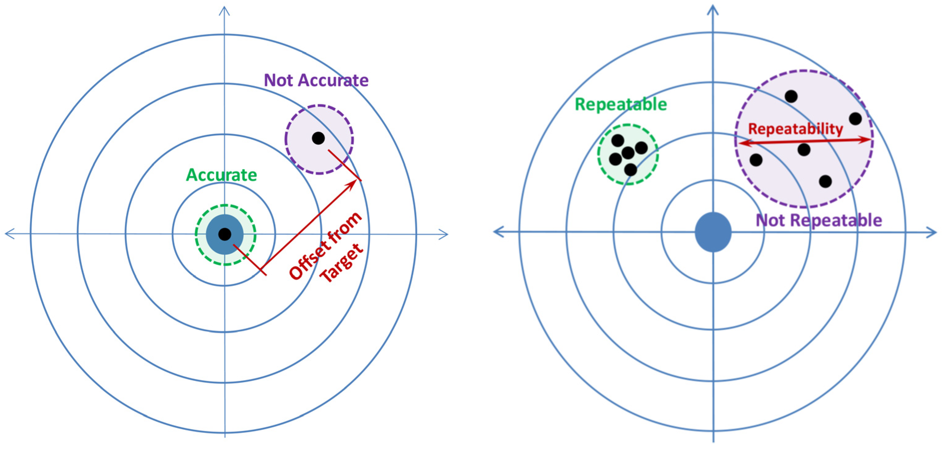
2.2.3. Accuracy and Repeatability

Accuracy ( A c ) and repeatability ( R p ) are the main measurable characteristics or indicators used as performance characteristics of fluid dispensing equipment such as robotic arms. The A c means how close an applied position is to a predetermined position [43], the error between the desired and obtained position. This indicator shows the ability of a robotic system to reach a commanded position with a minor error. The R p is a parameter to reach ideal results during several experiments [43]. In other words, it was defined as the ability of a robotic system to achieve the repetition of a position (Figure 4). The A c and R p of the system were tested in each development stage with considering the motion effects of the platform in stages III and IV. The position measurements had to carry out after a complete stop of the EE’s motion [44]. The main objective of this section is to achieve smaller accuracy and repeatability numbers which indicates tighter groupings within the test data distribution. In this regard, the tests were completed in different positions with ten repetitions. Each point was set in one segment to evaluate the differences (Table 1). The Z-value of each test on each stage could be different. Geometrically, the R p was defined as the radius of the smallest sphere that encompasses all the positions reached for the same requested position [45]. The A c is defined as the maximum errors for several positions distributed inside the reference frame. Mathematically, the A c and R p were calculated by the following equations.
A p x = 1 n 1 i = 1 n 1 ( x ¯ x c ) 2 ;   A p y = 1 n 1 i = 1 n 1 ( y ¯ y c ) 2 ;   A p z = 1 n 1 i = 1 n 1 ( z ¯ z c ) 2
L i = ( x r x ¯ ) 2 + ( y r y ¯ ) 2 + ( z r z ¯ ) 2
L ¯ = 1 n 2 i = 1 n 2 L i
R p = 3   i = 1 n 2 ( L i L ¯ ) 2 n 1   + L ¯
Which A p i , n 1 , n 2 , x ¯ , x c , and x r are positional accuracy, number of attained points in each mission, number of repetitions, and the average value of the attained position, commanded position, and reached position, respectively. In this section, the ANSI/RIA R15.05 standards were used.

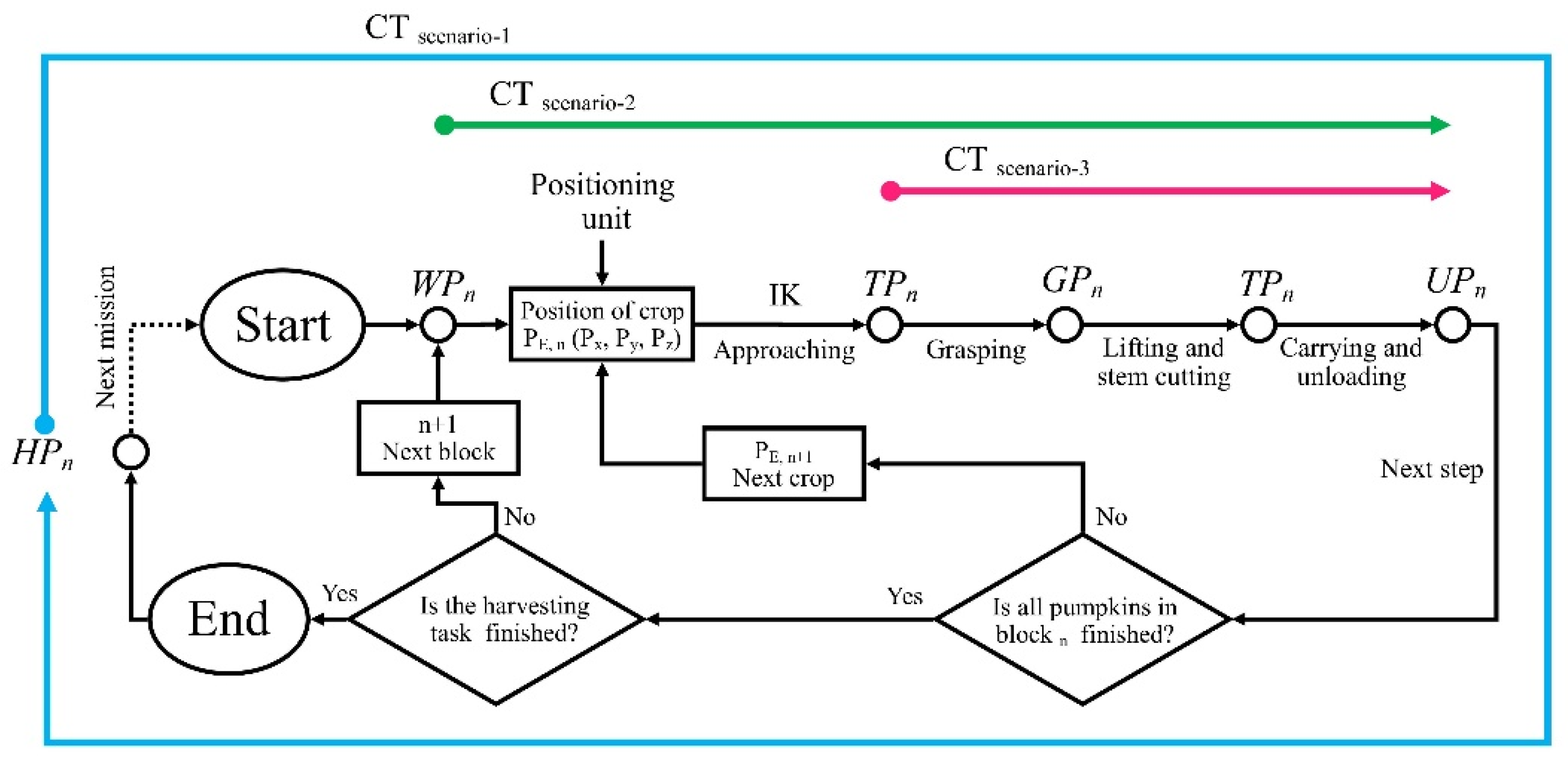
2.2.4. Harvesting Performance Indicators

The harvesting success rate (HSR), harvesting cycle time (CT), and damage rate (DR) are three main parameters that indicate the quality of the newly developed robotic system. In this study, these indicators were evaluated in ten repetitions based on the methodology presented by Roshanianfard, Kamata and Noguchi [31], as shown in Table 2. Roshanianfard, Kamata and Noguchi [31] selected HSR during the entire operation (from recognition of product position to the stage of placing it in the trailer). Any damage during this period counted as a failure. The harvesting procedure was divided into five stages, including home position ( H P ), working position ( W P ), target position ( T P ), grasping position ( G P ), and unloading position ( U P ). The CT was measured in three scenarios, as illustrated in Figure 5 and described in Table 3. In the evaluation of DR, the pumpkins should be utterly intact during operation.

3. Results and Discussion

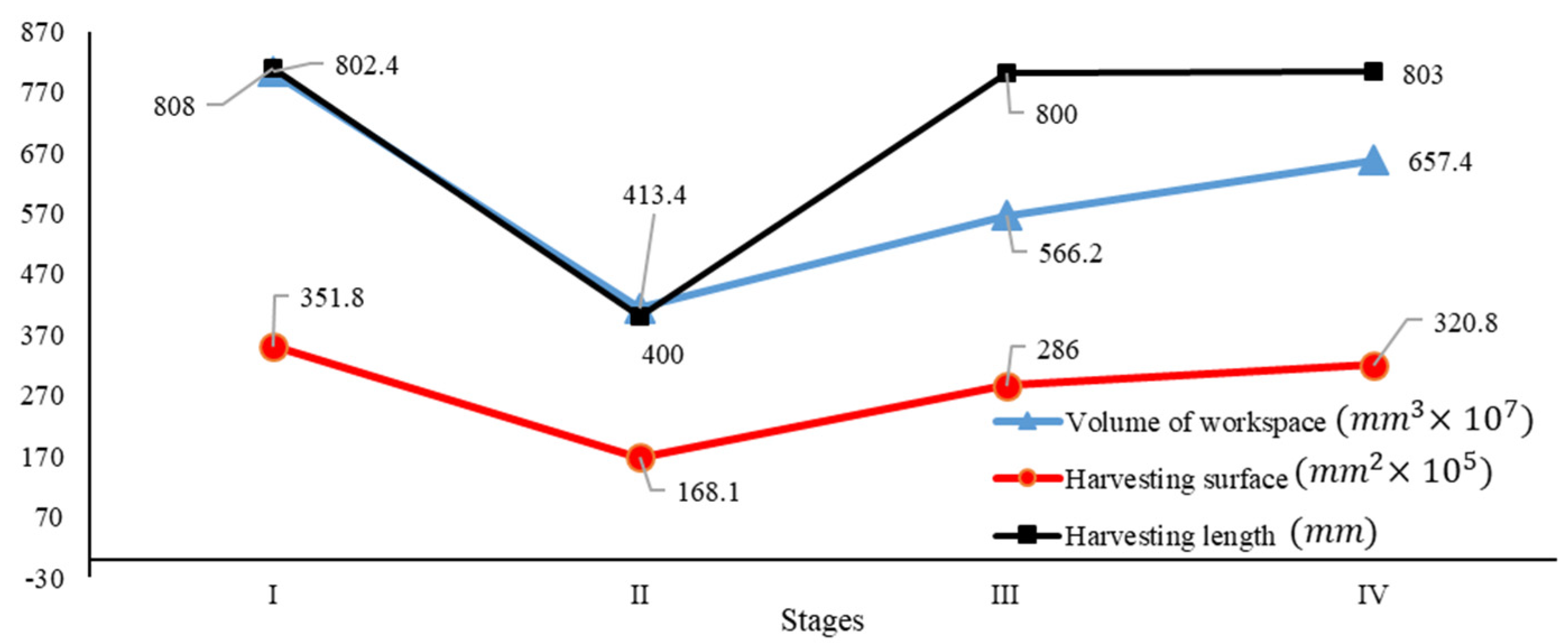
3.1. Workspace Results

The results indicated that the V , S c , and H L of the designed system was 8.024 × 10 9   mm 3 , 3.518 × 10 6   mm 2 , and 808   mm , respectively (Figure 6). Nevertheless, after development, these parameters were reduced to 51.52 , 47.78 , and 49.5 % of the designed parameters, respectively (Figure 7), which were 4.134 × 10 9   mm 3 , 1.681 × 10 6   mm 2 , and 400   mm , respectively. As these results were not meet the requirements, some modifications in the structure, including spacer removal, pulley and belt power transmission, link modification, and recodification of the controlling algorithm, were applied, and the manipulation was installed on an RT (stage-III). After this modification, the V , S c , and H L reached 5.662 × 10 9   mm 3 , 2.86 × 10 6   mm 2 , and 800   mm , respectively. In this stage, the V , S c , and H L were increased by 19.04 , 33.58 , and 49.5 % , compared with the developed system, respectively, which was 70.56 , 81.36 , and 99 % , of desired parameters of the designed system, respectively. The significant difference between the parameters of stage II versus stage III was because of the platform’s stability. The temporary stage was a metal structure that fluctuated during operation and reduced the quality of motion. In stage III, the RT had less fluctuation and directly affected the accuracy and repeatability values. After this stage, the system was installed on another RT (stage-IV), and the modification was applied. In this stage, the V , S c , and H L increased by 11.36 , 9.82 , and 9.38 % in comparison to previous development, respectively, which was 81.92 , 91.18 , and 99.38 % of desired parameters of the designed system, respectively. As it is evident, there was no significant difference between the stage III and stage IV because, in both stages, a commercialized platform was used (stage-III: row-crop tractor Yanmar EG453, stage-IV: general-purpose tractor Yanmar YT5113)

3.2. Resolution

The results of S R experiments are presented in Figure 8. In Stage-I, the side lengths of the giant square were 39 and 43 mm on the x and Z axis instead of 40 mm, which means the system resolution is tolerant. According to the calculations, the S R x , S R y , and S R Z were 1 ± 0.075, 1 ± 0.05, and 1 ± 0.025 mm, respectively. The system can have a tolerance of 75, 50, and 25 μm in the X, Y and, Z axis, respectively (Table 5). The test was repeated when the manipulation system was installed on RT-1, and the results show that the S R x , S R y , and S R Z were 1 ± 0.273, 1 ± 0.36, and 1 ± 0.381 mm, respectively. The system tolerates 273, 360 and 381 μm in the X, Y, and Z-axis, respectively (Table 5). These results indicated that the target installation platform and its vibration could harm the resolution of manipulation. After final installation on YT 5113, the results showed that the S R x , S R y , and S R Z were 1 ± 0.372, 1 ± 0.259, and 1 ± 0.388 mm, respectively. The system tolerate of 372, 259, and 388   μ m in the X, Y, and Z axis, respectively (Table 4). Between stages III and IV, there were no significant differences indicated. However, the resolution tolerance decreased due to mobile platforms, but this tolerance had no significant effects on the general performance of the designed system. Based on the archived results, the resolution values met the requirements and defined objectives for agricultural application. A resolution of 5 mm is acceptable for an actual agricultural field. The presented robotic system is more accurate than the required and desired indicator (Figure 8).

3.3. Accuracy and Repeatability

As results show, in stage II, the A c average   was 10.91 mm in the x-direction, 9.52 mm in the y-direction, and R p average   was 12.74 mm (Figure 9). The A c max in x and y directions were belonged to point-2 by 2.55 mm, and point-9 by 0.83 mm, respectively. The R p max   belonged to point-4 by 8.1 mm. The A c x of points 4, 6, 7, and 9 were more than the A c x .   average   , and the A c y of points 1, 2, 4, and 7 were more than the A c y .   average   . In stage III, The A c average   was 5.22mm in the x-direction, and 4.02mm in the y-directions, and also R p average   was 5.23 mm. The A c max   in x and y directions were belonged to point-10 by 1.43 mm, and 0.50 mm, respectively. The R p max   was belonged to point-9 by 3.56 mm. The A c x   of points 2, 3, 6, 9, and 11 were more than the A c x .   average   and the A c y of points 3, 4, 7, and 9 were more than the A c y .   average . In stage IV, The A c average   was 5.8mm in x-direction, and 4.78mm in y-directions, and also R p average   was 5.11mm, which is almost the same as stage III. The A c max   in the x and y directions were belonged to point-5 by 3.89 mm, and point-10 by 2.56 mm, respectively. The R p max   was belonged to point-5 by 2.38 mm. The A c x   of points 3, 9, 10, and 11 were more than the A c x .   average   and the A c y of points 1, 4, 5, 6, 8, and 9 were more than the A c y .   average   .
The results showed no relation between accuracy/repeatability with the position of selected points (Table 5). The R p of the points had no significant difference compared with R p average . No relationship between the distance of points versus its A c and R p was found. Based on these results, the average values of each parameter are presented as the final A c x , A c y , and R p as 5.8, 4.78, and 5.11 mm, respectively. After evaluation, it was realized that the vibration of the temporary stage harmed A c and R p , and this was because of its mechanical structure. This condition changed when the robotic arm was installed on a stable platform. The same experimentations in stages III and IV showed that the accuracy and repeatability of the system were modified to 5.22, 4.02, and 5.23 mm for stage III, and 5.8, 4.78, and 5.11 mm for stage IV, respectively. The result showed that the vibration of operation because of the temporary stage had a negative impact on these indicators. The resulted parameters are sufficient enough to do the harvesting procedure for heavyweight crops. In this application, an 8mm accuracy and repeatability were the required values, and the designed system is more accurate than the requirements.

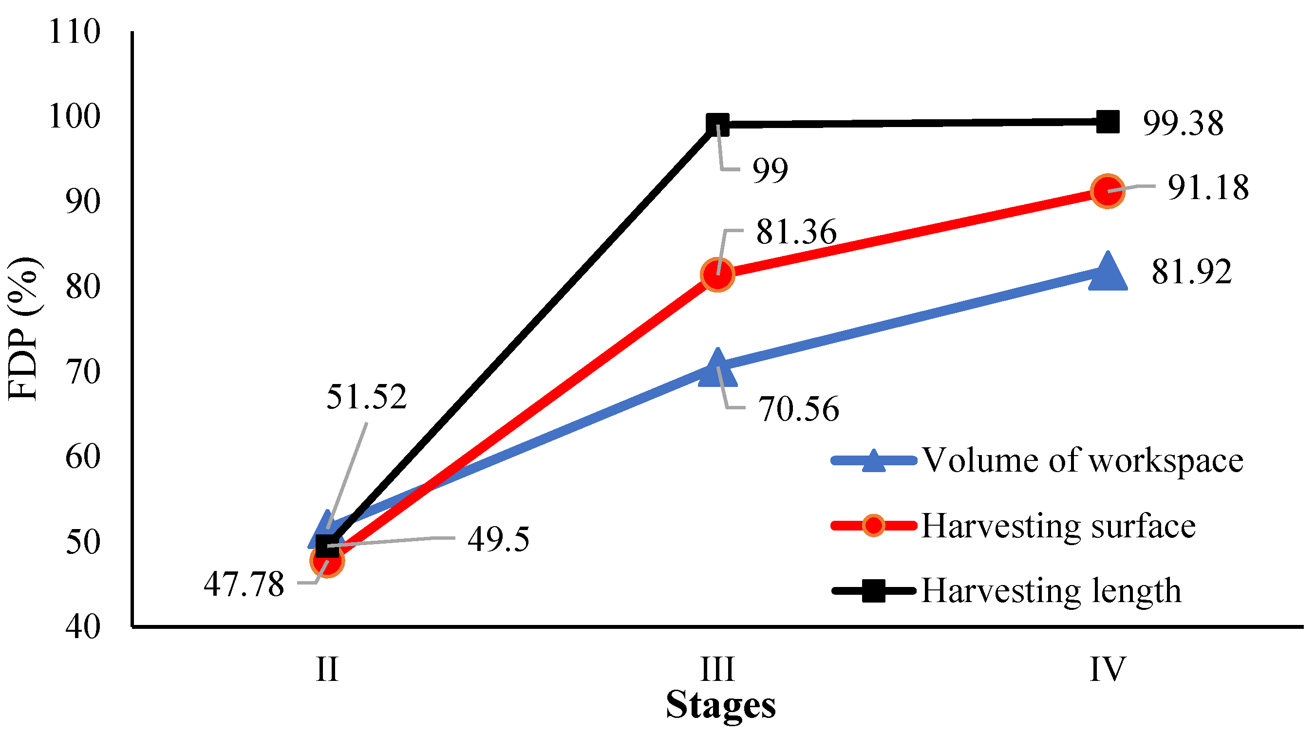
3.4. Workspace Indicators

As shown in Table 6, the average HSR of the HRHC system in stages II, III, and IV were 92, 88, and 87, respectively, which is sufficient for a prototype system. The failures in some points were because of the distance of the target point from the home position. It was also because of delays during control, and it improved during algorithm updates. These results clearly showed that the system has reliable parameters in its workspace. No damage was recognized during operation in stage II (Table 6). It was because of a laboratory environment. In stages III and IV, the damage rate was almost 5% in the actual field. This damage was caused by variation in the orientation of the pumpkin and the accuracy of positioning.
The results of CT in stage II showed that the average C T scenarios - 1 , C T scenarios - 2 , and C T scenarios - 2 were 58.7 s, 41.9 s, and 35.1 s, respectively. These indicators in stage III were 62.6, 50.7, and 42.6 s, and in stage IV were 63.1, 50.9, and 43.2 s, respectively. The values of average CT have no significant difference between stages III and IV because the difference in the platform could not significantly impact harvesting success results. These values have increased slightly compared with stage-II due to differences in the configuration and size of the platforms and experimented environment. The values of C T scenarios - 3 are a valuable indicator because it indicates the traveling time between two harvestings in a repetitive harvesting mission on the actual field. Based on this indicator, it can result that the system completed the harvesting procedure in less than one minute for each target crop. In C T scenarios - 3 the time-traveling between HP and TP was excluded because, in an actual field, the system harvests a crop unloads it and does this process again and again. The C T scenarios - 1 for stages II, III, IV was 58.7, 62.6, and 63.1, respectively, which was 57.7, 61.6, and 62% more than C T scenarios - 2 , respectively. Scenario-1 included all steps of harvesting, including the location indication, harvesting, and carrying to the trunk. The C T scenarios - 2 was evaluated during motion between W P n and U P n , and the consumed time for position detection was ignored. The results showed that the system consumed 19~28% of CT to the determined position of the target crop, data evaluation, and transmutation. It can conclude that if the processing speed of the control unit has improved by component modification, the system can finish the entire process with 75% of the CT. Although the HRHC system has an excellent capability to perform the harvesting process, the modification was applied to improve the value of indicators in different parts of it. Despite sevral advances developing robotic arms, e.g., [45,46,47,48,49,50,51], for the future work, in order to improve the results applying advanced evolutionary algorithms and machine learning methods, e.g., [52,53,54,55,56,57] for optimizing the design and improving the performance.

4. Conclusions

This study presented a harvesting robot’s development and performance evaluation for heavyweight crops called HRHC. Pumpkin was used as an example of a heavyweight for evaluation. Based on the findings, the following explanations can be concluded in the main components of the system. The mobile platform: The RTs are commercialized tractors that can maneuver autonomously. The RTs can have various applications for carrying objects, harvesting, plowing, seeding, cultivation, and most farm applications. Robotic arm: The developed robotic arm is mostly designed for farm applications, which is not accurate for very precise applications such as car production lines or circuit assembly. However, it is a practical system for farm application, carrying objects, horticulture application, etc. End effector: The designed end-effector is designed explicitly for pumpkin harvesting. Changing the fingers can be applied to many more objects, including agricultural products. Controlling system: This unit can have applications in many industries with some minimal modifications. The system was designed, manufactured, and evaluated using standard methodologies. Various performance parameters were tested, including Ac, Rp, WS, HS, HL, DR, HSR, CT, and CR, presented in Table 7, and the performance was compared with previous studies. The review paper presented by Bac, et al. [46] reported that between almost 50 projects to develop robotic harvesting systems for agricultural products such as apple, orange, kiwi, and strawberries between 1984 and 2014, there was no practical harvesting robot commercialized. However, there was some commercialized harvesting robot between 2012 and 2020, such as “Rubion” for strawberry harvesting [47] and “SWEEPER” for sweet pepper harvester [48]. The H S R , C T , and D R compared in some of the mentioned studies, and other parameters including V , A c , R p and many others have not been mentioned.
The H S R of the HRHC system (87~92%) is higher than the H S R a v e r a g e of previous studies (66%). The D R of the HRHC system (5~7%) is almost the same as the D R a v e r a g e of previous studies (5%). The C T of the HRHC system (overall average = 49.86 s) is in the range of C T a v e r a g e of previous studies (1 ~ 227 s). This value is more extensive than similar research, such as melon harvester by 15s [49], heavy material manipulator by 14s [50], and robot for watermelon by 15s [51]. It means the CT of the HRHC system requires improvement. In conclusion, the mentioned indicators are improvable by mechanical optimization and improvement of the controlling system. Most of the outputs meet the required parameters, and the HRHC system’s final version was applied to the target task.

Author Contributions

Conceptualization, A.R. and N.N.; Data curation, A.R.; Formal analysis, A.R.; Funding acquisition, A.M.; Methodology, A.R.; Project administration, N.N.; Software, C.M.; Supervision, A.M., C.M.; Validation, S.A.; Visualization, A.M. and S.A.; Writing—original draft, A.R.; Writing—review & editing, A.M., S.A. and C.M. All authors have read and agreed to the published version of the manuscript.

Funding

The authors gratefully acknowledge the contribution of the Slovak Research and Development Agency under the project APVV-20-0261. In addition, this research is partially supported by the European Union’s Horizon 2020 Research and Innovation Programme under the Programme SASPRO 2 COFUND Marie Sklodowska-Curie under Grant 945478.

Institutional Review Board Statement

Not applicable.

Informed Consent Statement

Not applicable.

Data Availability Statement

Not applicable.

Acknowledgments

This study was supported by the Cross-ministerial Strategic Innovation Promotion Program (SIP) managed by Cabinet Office.

Conflicts of Interest

The authors declare no conflict of interest.

References

  1. WPP. World Population Prospects. Available online: https://population.un.org/wpp/ (accessed on 21 March 2022).
  2. Mizushima, A.; Noguchi, N.; Ishii, K. Development of Robot Tractor Using the Low-Cost GPS/INS System; American Society of Agricultural and Biological Engineers: St. Joseph, MI, USA, 2005. [Google Scholar]
  3. Liu, Y.; Noguchi, N.; Ishii, K. Development of a Low-cost IMU by Using Sensor Fusion for Attitude Angle Estimation. IFAC Proc. Vol. 2014, 47, 4435–4440. [Google Scholar] [CrossRef] [Green Version]
  4. Yin, X.; Noguchi, N. Motion Detection and Tracking Using the 3D-camera. IFAC Proc. Vol. 2011, 44, 14139–14144. [Google Scholar] [CrossRef] [Green Version]
  5. Noguchi, N.; Barawid, O.C. Robot Farming System Using Multiple Robot Tractors in Japan Agriculture. IFAC Proc. Vol. 2011, 44, 633–637. [Google Scholar] [CrossRef] [Green Version]
  6. Roshanianfard, A.; Noguchi, N.; Okamoto, H.; Ishii, K. A review of autonomous agricultural vehicles (The experience of Hokkaido University). J. Terramechanics 2020, 91, 155–183. [Google Scholar] [CrossRef]
  7. Noguchi, N.; Terao, H. Path planning of an agricultural mobile robot by neural network and genetic algorithm. Comput. Electron. Agric. 1997, 18, 187–204. [Google Scholar] [CrossRef]
  8. Noguchi, N. Vision Intelligence for Mobile Agro-Robotic System. J. Robot. Mechatron. 1999, 11, 193–199. [Google Scholar] [CrossRef]
  9. Zhang, Q.; Reid, J.F.; Noguchi, N. Agricultural vehicle navigation using multiple guidance sensors. In Proceedings of the International Conference on Field and Service Robotics, Pittsburgh, PA, USA, 29–31 August 1999. [Google Scholar]
  10. Mizushima, A.; Noguchi, N.; Ishii, K.; Terao, H.; Yukumoto, O.; Yamamoto, S. Automatic Guidance System Composed of Geomagnetic Direction Sensor and Fiber Optic Gyroscope. IFAC Proc. Vol. 2000, 33, 313–317. [Google Scholar] [CrossRef]
  11. Ryo, T.; Noguchi, N.; Akira, M. Automatic guidance with a laser scanner for a robot tractor in an orchard. In Proceedings of the Automation Technology for Off-Road Equipment, Kyoto, Japan, 7–8 October 2004. [Google Scholar]
  12. Monte, A.D.; Noboru, N.; Qin, Z.; John, F.R.; Jeffrey, D.W. Sensor-fusion navigator for automated guidance of off-road vehicles. J. Terramechanics 2000, 50, 211–232. [Google Scholar]
  13. Michio, K.; Noboru, N.; Kazunobu, I.; Hideo, T. Field mobile robot navigated by RTK-GPS and FOG (Part 1)—Estimation of absolute heading angle by sensor-fusion with RTK-GPS and FOG. J. Jpn. Soc. Agric. Mach. 2001, 63, 74–79. [Google Scholar] [CrossRef]
  14. Michio, K.; Noboru, N.; Kazunobu, I.; Hideo, T. Field mobile robot navigated by RTK-GPS and FOG (Part 2)—Autonomous operation by applying navigation map. J. Jpn. Soc. Agric. Mach. 2001, 63, 80–85. [Google Scholar] [CrossRef]
  15. Kise, M.; Noguchi, N.; Ishii, K.; Terao, H. Development of the Agricultural Autonomous Tractor with an RTK-GPS and a Fog. IFAC Proc. Vol. 2001, 34, 99–104. [Google Scholar] [CrossRef]
  16. Noguchi, N.; Reid, J.F.; Zhang, Q.; Will, J.D. Turning function for robot tractor based on spline function. In Proceedings of the 2001 ASAE Annual Meeting, Sacramento, CA, USA, 29 July–1 August 2001. [Google Scholar]
  17. Kise, M.; Noguchi, N.; Ishii, K.; Terao, H. Enhancement of turning accuracy by path planning for robot tractor. In Proceedings of the Automation Technology for Off-Road Equipment, Chicago, IL, USA, 26–27 July 2002; pp. 398–404. [Google Scholar]
  18. Kise, M.; Noguchi, N.; Ishii, K.; Terao, H. The development of the autonomous tractor with steering controller applied by optimal control. In Proceedings of the Automation Technology for Off-Road Equipment, Chicago, IL, USA, 26–27 July 2002; pp. 367–373. [Google Scholar]
  19. Noguchi, N.; Will, J.; Reid, J.; Zhang, Q. Development of a master–slave robot system for farm operations. Comput. Electron. Agric. 2004, 44, 1–19. [Google Scholar] [CrossRef]
  20. Takai, R.; Barawid, O.; Ishii, K.; Noguchi, N. Development of Crawler-Type Robot Tractor based on GPS and IMU. IFAC Proc. Vol. 2010, 43, 151–156. [Google Scholar] [CrossRef]
  21. Takai, R.; Barawid, O.; Noguchi, N. Autonomous Navigation System of Crawler-Type Robot Tractor. IFAC Proc. Vol. 2011, 44, 14165–14169. [Google Scholar] [CrossRef]
  22. Zhang, Z.; Noguchi, N.; Ishii, K.; Yang, L.; Zhang, C. Development of a Robot Combine Harvester for Wheat and Paddy Harvesting. IFAC Proc. Vol. 2013, 46, 45–48. [Google Scholar] [CrossRef]
  23. Liu, Y.; Noguchi, N.; Roshanianfard, A. Simulation and test of an agricultural unmanned airboat maneuverability model. Int. J. Agric. Biol. Eng. 2017, 10, 88–96. [Google Scholar] [CrossRef]
  24. Roshanianfard, A.; Mengmeng, D.; Nematollahzadeh, S. A 4-DOF SCARA Robotic Arm for Various Farm Applications: Designing, Kinematic Modelling, and Parameterization. Acta Technol. Agric. 2021, 24, 61–66. [Google Scholar] [CrossRef]
  25. Wang, X.; Kang, H.; Zhou, H.; Au, W.; Chen, C. Geometry-aware fruit grasping estimation for robotic harvesting in apple orchards. Comput. Electron. Agric. 2022, 193, 106716. [Google Scholar] [CrossRef]
  26. Roshanianfard, A.; Noguchi, N. Characterization of pumpkin for a harvesting robot. IFAC-PapersOnLine 2018, 51, 23–30. [Google Scholar] [CrossRef]
  27. Roshanianfard, A.; Noguchi, N. Development of a 5DOF robotic arm (RAVebots-1) applied to heavy products harvesting. IFAC-PapersOnLine 2016, 49, 155–160. [Google Scholar] [CrossRef]
  28. Qiao, N.; Wang, L.; Liu, M.; Wang, Z. The sliding mode controller with improved reaching law for harvesting robots. J. Intell. Robot. Syst. 2022, 104, 9. [Google Scholar] [CrossRef]
  29. Roshanianfard, A.; Noguchi, N. Pumpkin harvesting robotic end-effector. Comput. Electron. Agric. 2020, 174, 105503. [Google Scholar] [CrossRef]
  30. Abbaspour-Gilandeh, Y.; Fazeli, M.; Roshanianfard, A.; Hernández-Hernández, M.; Gallardo-Bernal, I.; Hernández-Hernández, J.L. Prediction of Draft Force of a Chisel Cultivator Using Artificial Neural Networks and Its Comparison with Regression Model. Agronomy 2020, 10, 451. [Google Scholar] [CrossRef] [Green Version]
  31. Dattatraya, G.D.; Mhatardev, M.V.; Shrihari, L.M.; Joshi, S.G. Robotic agriculture machine. Int. J. Innov. Res. Sci. Eng. Technol. 2014, 3, 454–462. [Google Scholar]
  32. Roshanianfard, A.; Shahgholi, G. Performance Characterization of Automatic Creep Testing Device for Agricultural Product. Appl. Eng. Agric. 2017, 33, 433–440. [Google Scholar] [CrossRef]
  33. Deshpande, V.; George, P.M. Kinematic modelling and analysis of 5 DOF robotic arm. Int. J. Robot. Res. Dev. 2014, 4, 17–24. [Google Scholar]
  34. Kamata, T.; Roshanianfard, A.; Noguchi, N. Heavy-weight Crop Harvesting Robot—Controlling Algorithm. IFAC-PapersOnLine 2018, 51, 244–249. [Google Scholar] [CrossRef]
  35. Oliveira, L.F.; Moreira, A.P.; Silva, M.F. Advances in agriculture robotics: A state-of-the-art review and challenges ahead. Robotics 2021, 10, 52. [Google Scholar] [CrossRef]
  36. Lytridis, C.; Kaburlasos, V.G.; Pachidis, T.; Manios, M.; Vrochidou, E.; Kalampokas, T.; Chatzistamatis, S. An Overview of Cooperative Robotics in Agriculture. Agronomy 2021, 11, 1818. [Google Scholar] [CrossRef]
  37. Rose, D.C.; Lyon, J.; de Boon, A.; Hanheide, M.; Pearson, S. Responsible development of autonomous robotics in agriculture. Nat. Food 2021, 2, 306–309. [Google Scholar] [CrossRef]
  38. Kootstra, G.; Wang, X.; Blok, P.M.; Hemming, J.; Van Henten, E. Selective harvesting robotics: Current research, trends, and future directions. Curr. Robot. Rep. 2021, 2, 95–104. [Google Scholar] [CrossRef]
  39. Khadatkar, A.; Mehta, C.R.; Sawant, C.P. Application of robotics in changing the future of agriculture. J. Eco-Friendly Agric. 2022, 17, 48–51. [Google Scholar] [CrossRef]
  40. Zhang, C. Development of a Multi-Robot Tractor System for Farm Work. Ph.D. Thesis, Hokkaido University, Hokkaido, Japan, 2017. [Google Scholar]
  41. Takai, R.; Yang, L.; Noguchi, N. Development of a crawler-type robot tractor using RTK-GPS and IMU. Eng. Agric. Environ. Food 2014, 7, 143–147. [Google Scholar] [CrossRef]
  42. Yang, L.; Noguchi, N.; Takai, R. Development and application of a wheel-type robot tractor. Eng. Agric. Environ. Food 2016, 9, 131–140. [Google Scholar] [CrossRef]
  43. ASYMTEK Nordson. Making Sense of Accuracy, Repeatability and Specification for Automated Fluid Dispensing Systems. Available online: https://smtnet.com/library/files/upload/Making-Sense-of-Accuracy-and-Repeatability-NordsonASYMTEK.pdf (accessed on 21 March 2022).
  44. Groover, M.P. Industrial robotics. In Automation, Production Systems, and Computer Integrated Manufacturing; Prentice Hall Press: Upper Saddle River, NJ, USA, 2008. [Google Scholar]
  45. ISO 9283:1998; Manipulating Industrial Robots—Performance Criteria and Related Test Methods. International Organization for Standardization: Geneva, Switzerlnd, 1998.
  46. Bac, C.W.; van Henten, E.J.; Hemming, J.; Edan, Y. Harvesting Robots for High-value Crops: State-of-the-art Review and Challenges Ahead. J. Field Robot. 2014, 31, 888–911. [Google Scholar] [CrossRef]
  47. Octinion. PRESS RELEASE: Octinion Presents the World’s First Strawberry Picking Robot. Available online: http://octinion.com/news/press-release-octinion-presents-world%E2%80%99s-first-strawberry-picking-robot (accessed on 21 January 2022).
  48. Sweeper. SWEEPER Demonstrated its Harvesting Robot for the First Time. Available online: http://www.sweeper-robot.eu/11-news/48-sweeper-demonstrated-its-harvesting-robot-for-the-first-time (accessed on 21 January 2022).
  49. Yael, E.; Dima, R.; Tamar, F.; Gaines, E.M. Robotic melon harvesting. IEEE Trans. Robot. Autom. 2000, 16, 831–835. [Google Scholar] [CrossRef]
  50. Sakai, S.; Iida, M.; Osuka, K.; Umeda, M. Design and control of a heavy material handling manipulator for agricultural robots. Auton. Robot. 2008, 25, 189–204. [Google Scholar] [CrossRef] [Green Version]
  51. Heon, H.; Si-Chan, K. Development of multi-functional tele-operative modular robotic system for greenhouse watermelon. In Proceedings of the 2003 IEEE/ASME International Conference on Advanced Intelligent Mechatronics (AIM 2003), Kobe, Japan, 20–24 July 2003; Volume 1342, pp. 1344–1349. [Google Scholar]
  52. Chen, H.; Heidari, A.A.; Chen, H.; Wang, M.; Pan, Z.; Gandomi, A.H. Multi-population differential evolution-assisted Harris hawks optimization: Framework and case studies. Future Gener. Comput. Syst. 2020, 111, 175–198. [Google Scholar] [CrossRef]
  53. Shan, W.; Qiao, Z.; Heidari, A.A.; Chen, H.; Turabieh, H.; Teng, Y. Double adaptive weights for stabilization of moth flame optimizer: Balance analysis, engineering cases, and medical diagnosis. Knowl.-Based Syst. 2020, 214, 106728. [Google Scholar] [CrossRef]
  54. Hu, J.; Chen, H.; Heidari, A.A.; Wang, M.; Zhang, X.; Chen, Y.; Pan, Z. Orthogonal learning covariance matrix for defects of grey wolf optimizer: Insights, balance, diversity, and feature selection. Knowl.-Based Syst. 2021, 213, 106684. [Google Scholar] [CrossRef]
  55. Zhang, Y.; Liu, R.; Heidari, A.A.; Wang, X.; Chen, Y.; Wang, M.; Chen, H. Towards Augmented Kernel Extreme Learning Models for Bankruptcy Prediction: Algorithmic Behavior and Comprehensive Analysis. Neurocomputing 2020, 430, 185–212. [Google Scholar] [CrossRef]
  56. Zhao, D.; Liu, L.; Yu, F.; Heidari, A.A.; Wang, M.; Liang, G.; Muhammad, K.; Cheng, H. Chaotic random spare ant colony optimization for multi-threshold image segmentation of 2D Kapur entropy. Knowl.-Based Syst. 2020, 216, 106510. [Google Scholar] [CrossRef]
  57. Tu, J.; Chen, H.; Liu, J.; Heidari, A.A.; Zhang, X.; Wang, M.; Wang, M.; Ruby, R.; Pham, Q.-V. Evolutionary biogeography-based Whale optimization methods with communication structure: Towards measuring the balance. Knowl.-Based Syst. 2020, 212, 106642. [Google Scholar] [CrossRef]
Figure 1. The HRHC system (a) required systems for operation, (b) components for operation, and (c) detailed components.
Agronomy 12 01594 g001
Figure 2. Development stages: (I) design, (II) adjustments and evaluation, (III) implementation, (IV) installation/operation.
Agronomy 12 01594 g002
Figure 3. (a) Illustration of parameters related to the workspace, (b) a 3D view of workspace, (c) workspace cross-section.
Agronomy 12 01594 g003
Figure 4. Accurate and non-accurate comparison (left), and repeatable and non-repeatable comparison (right).
Agronomy 12 01594 g004
Figure 5. Illustration of controlling procedure with different scenarios for cycle time.
Agronomy 12 01594 g005
Figure 6. The workspace parameters in the different stages.
Agronomy 12 01594 g006
Figure 7. FDP of development stages.
Agronomy 12 01594 g007
Figure 8. Resolution test sample (a) Desired path and (b) experimentation result.
Agronomy 12 01594 g008
Figure 9. The polar plots of Ac and Rp.
Agronomy 12 01594 g009
Table 1. Target position tested for accuracy and repeatability test.
Position No.X (mm)Y (mm)
1500−1470
21200−1200
31450500
4700950
5550−1150
61400−700
75501350
8950−450
91100250
10115020
111500900
Table 2. Harvesting performance indicators.
IndicatorEquationUnit
HSR S u c c e s s f u l   h a r v e s t s T o t a l h a r v e s t s × 100 %
CT h a r v e s t i n g   o p e r a t i o n   t i m e s
DR I n t a c t   h a r v e s t e d   c r o p T o t a l   h a r v e s t e d   c r o p × 100 %
Table 3. Harvesting performance indicators.
IndicatorDescriptionStart PointENDPOINT
CTScenario-1The consumed time for full harvesting procedures plus transportation to the next crop plus time loss because of failed attemptsUPnUP(n+1)
CTScenario-2The consumed time for harvesting each pumpkinWPnUPn
CTScenario-3The consumed time between the target position to unloading position in the same stepTPnUPn
Table 4. System resolution.
StageSR ± Tolerance (mm)
XYZ
I1 ± 0.0751 ± 0.0501 ± 0.025
II1 ± 0.2731 ± 0.3601 ± 0.381
IV1 ± 0.3721 ± 0.2591 ± 0.388
Table 5. Ac and Rp results.
ParametersExperiment PositionsAverage (mm)
1234567891011
IIAccuracyx5.522.555.3923.774.5615.514.6610.715.5610.2311.5710.91
y20.7714.587.619.12.813.5318.163.240.833.9210.29.52
Repeatability13.912.2714.568.114.712.4712.2612.5312.8712.6513.8312.74
IIIAccuracyx4.267.296.592.734.665.244.851.5111.671.437.205.22
y0.640.338.499.592.003.834.153.378.800.501.984.02
Repeatability4.624.874.845.745.776.015.236.093.566.154.635.23
IVAccuracyx4.484.667.025.553.743.895.764.047.59.47.775.8
y5.24.723.54.895.765.763.775.098.32.563.044.78
Repeatability4.626.35.085.672.384.335.663.985.275.45.875.11
TS = Temporary stage.
Table 6. HSR results.
StageCT (Scenario-1)CT (Scenario-2)CT(Scenario-3)CT (Average)HSR (%)DR (%)
II58.741.935.145.23920
III62.650.742.651.96885 ~ 7
IV63.150.943.252.4875 ~ 7
Table 7. Performance indicators of HRHC system.
ParameterStageUnit
IIIIIIV
Accuracy-X (Acx)10.915.225.8mm
Accuracy-Y (Acy)9.524.024.78mm
Repeatability (Rp)12.745.235.11mm
Workspace volume (V)4.1345.6626.574×109 mm3
Harvesting surface (HS)1.6812.863.208×106 mm2
Harvesting length (HL)400800803mm
Damage rate (DR)055%
Harvest success rate (HSR)928887%
cycle time (CT)Scenario-158.762.663.1s
Scenario-241.950.750.9s
Scenario-335.142.643.2s
Control resolution (CR)X1 ± 0.0751 ± 0.2731 ± 0.372mm
Y1 ± 0.051 ± 0.361 ± 0.259mm
Z1 ± 0.0251 ± 0.3811 ± 0.388mm
Publisher’s Note: MDPI stays neutral with regard to jurisdictional claims in published maps and institutional affiliations.

