Abstract
The goal of this research was to analyze the load and safety of the transplanting device of the 4-bar link type semi-automatic vegetable transplanter under different workload conditions. To measure the strain at the transplanting device, a load measurement system was developed using 15 strain gauges. Field tests were conducted at 4 levels of engine speeds (750, 1000, 1250, and 1500 rpm) and 10 levels of the planting distance (0.29–0.47 m). The static safety factor was defined as the ratio between the strength of the material and the maximum stress in the transplanting device. The calculated stress data were converted from the time domain to the frequency domain using the rain-flow counting methods and Goodman’s Equation. The sum of fatigue damage was acquired based on the Palmgren–Miner’s rule. It was observed that the stresses increased with increasing engine speed and planting distance. The results show the higher engine speed and the longer planting distance will decrease the static safety factor and fatigue life. The static safety factor value was more than 1.0 for all locations and all working conditions. The minimum fatigue life was 49,153.3 h at link A (S_14), under the working condition of engine speed 750 rpm and planting distance of 0.35 m.
1. Introduction
A vegetable transplanter is a machine used for transferring vegetable seedlings from the nursery and transplanting them into the soil [1,2,3]. Vegetable transplanters are classified into full-automatic and semi-automatic according to the method of taking the seedlings out of the pot and putting them into the seedling cylinder. For a fully automatic transplanter, the seedlings are automatically taken out from the pot and put into the seedling cylinder so the work is easy and the work speed is fast. However, except for leafy vegetables with short plant lengths, formal work is difficult, and a dedicated pot tray must be used [4,5]. For a semi-automatic transplanter, the seedlings are picked by hand and put into the seedling cylinder. Although the work speed is slow, there are no restrictions on crops and pot trays, and the price is lower than the fully automatic transplanter [6]. Therefore, the semi-automatic vegetable transplanter is still being developed, especially for small-scale multi-variety cultivation [7].
In Korea, there are agricultural machinery companies that produce and sell the 4-bar link type semi-automatic vegetable transplanter. This type is widely used in Korea because of its simple structure and user-friendliness. Some research on a 4-bar link type semi-automatic vegetable transplanter has been conducted. Park et al. [8] investigated the operational characteristics of a 4-bar link type semi-automatic vegetable transplanter and analyzed the main functional components and power path of the transplanter. Jo et al. [9] improved the efficiency of the 4-bar link type semi-automatic vegetable transplanter by analyzing and modifying the linkage of the transplanting device.
In addition, to develop high-efficiency agricultural machinery, agricultural machine companies are also starting to consider the safety of agricultural machines because the users want machines that are safe to use without any failure during the service life [10,11]. The transplanting device is a part of vegetables transplanter to planting the seedling. For vegetable transplanter, the transplanting device is subjected to a large and repeated load because of the working mechanism when planting the seedling [8,9]. The load characteristics affect the life and durability of the transplanting device [12,13,14]. To ensure the safety of the transplanting device of a 4-bar link type semi-automatic vegetable can be carried out through load and safety analysis.
The load and safety analysis are carried out by measuring the strain or stress in the specific spot of a machine part. The sensor widely used to measure strain is the strain gauge [15,16,17]. There are two types of load and safety analysis approaches, namely static safety factor and dynamic safety analysis/fatigue life. The static safety factor is calculated using the maximum stress and yield strength of the material, while dynamic safety analysis the fatigue life was analyzed using a combination of the amount of fatigue damage obtained based on the Palmgren–Miner rule and the S-N curve [18,19,20,21,22,23,24,25]. The rain-flow counting method is needed to convert the stress data from the time domain to the frequency domain and Goodman’s Equation is used to calculate the equivalent completely reserved stress [26,27,28].
Several researchers have conducted load and safety analyses on transplanters. Kim et al. [29] analyzed loads of a transplanter PTO shaft during transplanting operations concerning planting distance. Kim et al. [30] constructed the PTO load spectrum from the measured load data using the rain-flow counting method and Smith–Watson–Topper (SWT) methods and analyzed the fatigue life of a small riding-type transplanter according to the planting distance and depth. Siddique et al. [31] analyzed the axle load of a rice transplanter when planting rice seedlings at different working load conditions to select a suitable gear stage and a constant planting depth for rice seedlings. Islam et al. [32] analyzed the stress of the picking device gear mechanism to select suitable materials and dimensions and to predict the fatigue life of the 2.6 kW automatic pepper transplanter. Although there have been some studies on load and safety in the transplanter, studies that analyzed the safety of the transplanter device of vegetable transplanter have not been conducted.
The objective of this study is to analyze the load and safety of the transplanting devices of a 4-bar link type semi-automatic vegetable transplanter according to the engine speed and planting distance. The safety in this study includes static safety and durability of the transplanting device of 4-bar link type vegetable transplanter. The specific objectives are: (1) to measure the strains on the selected spots of the transplanting device according to the engine speed and planting distance, (2) to calculate the static safety factor, and (3) to analyze the fatigue life of the transplanting device.
2. Materials and Methods
2.1. Vegetable Transplanter Used in This Study
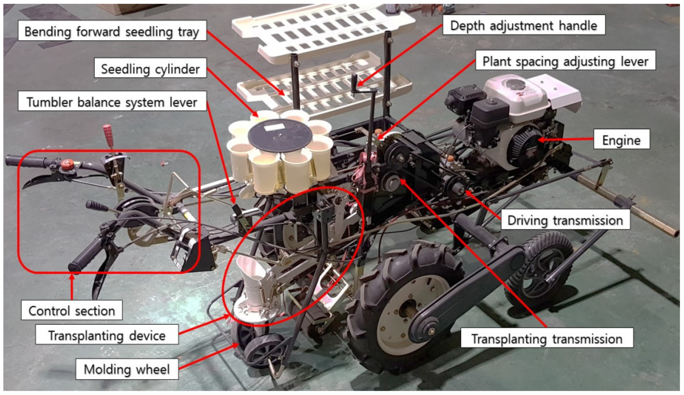
The shape and main specifications of the 4-bar link type semi-automatic vegetable transplanter used in this study are shown in Figure 1 and Table 1. The main components of this transplanter are as follows: a gasoline engine as the power source of the machine, a driving transmission to transmit the engine power to the driving unit and the planting unit, transplanting transmission to transmit the power received from the driving transmission to the crank of the planting device, control section consists of levers and handles to control the machine’s operation, a seedling cylinder to put the seedling, a transplanting device for planting the seedling, and a molding wheel to cover the planted seedling with soil.

Figure 1.
The shape of the 4-bar link type semi-automatic vegetable transplanter.

Table 1.
Specifications of the 4-bar link type semi-automatic vegetable transplanter.
The transplanter operates as follows. The user determines the planting distance by adjusting the number of shift stages of the transplanting transmission and selects a speed suitable for engine operation. The engine speed and moving speed of the transplanter are proportional. Therefore, the planting distance tends to long as the number of shift stages increases from one to ten, and the planting distance also longer as moving speed of the transplanter faster in forwarding direction. The engine speed is controlled through the throttle lever, the forward/reverse and neutral, high, and low speeds of the machine are controlled through the shift lever and main clutch lever. The transplanter moves in the forward direction and the transplanting device move up and down in a certain trajectory, as shown in Figure 2. The seedlings are taken out from the seedling tray and placed in the seedling cylinder manually. The seedling cylinder delivers the seedlings to the planting hopper, then the planting hopper moves down and is opened at the lowest position by the link device and at the same time planting the seedlings into the ground. After that, the molding wheel at the rear of the machine pushes the soil to both sides of the seedling to complete the planting.
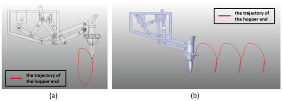
Figure 2.
The trajectory of the hopper end of the transplanting device: (a) at stationary condition, (b) at mobile condition.
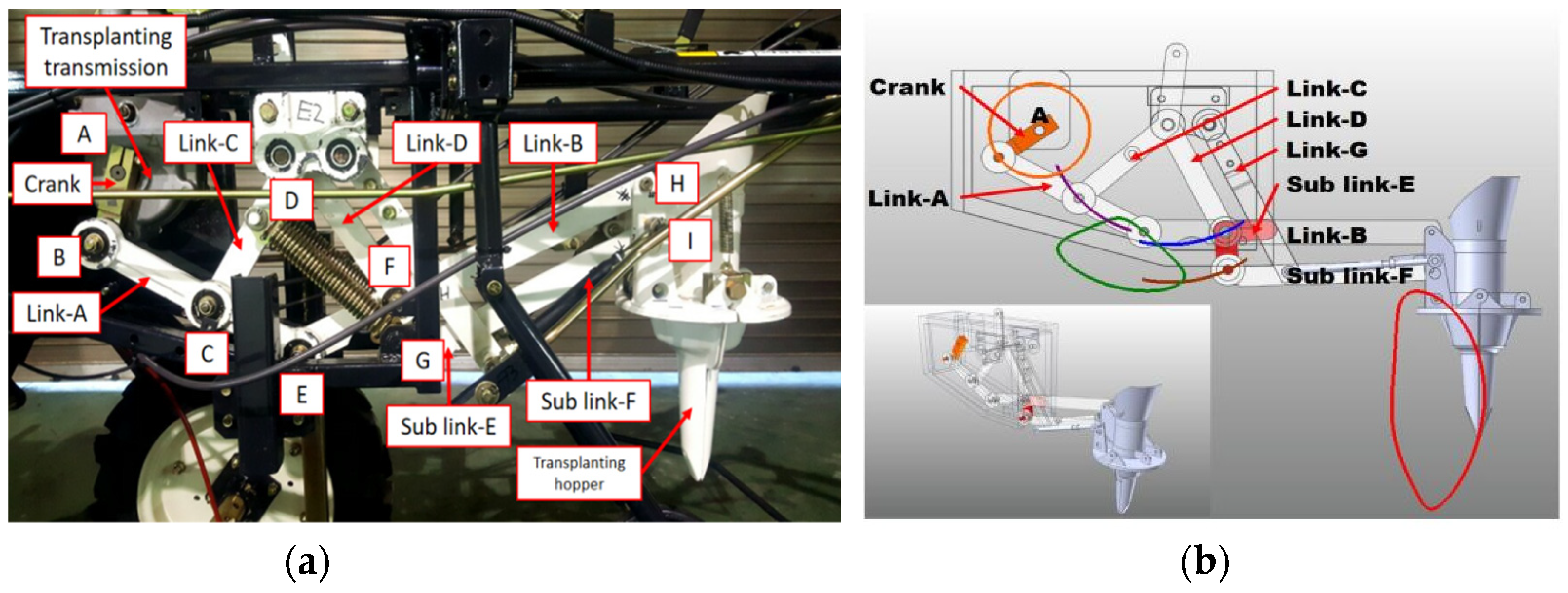
The part that plays an important role in transplanting work is the transplanting device. The shape of the transplanting device is shown in Figure 3a. The transplanting device consists of link and hopper. The link of the planting device consists of a total of 10 links and 13 rotary joints, including 6 binary links, 3 ternary links, and 1 ground. The shape of the transplanting hopper is an inverted cone, and it can be opened and closed by two springs connected to the planting device link at the bottom of both sides. A 4-bar link performs formal work by the continuous and repeated behavior of each link device. The drive shaft in the transplanting transmission transmitted the power to the link through the crank. The movement of the hinge point (A) as shown in Figure 3b. The size of crank is 112 mm, while the size of link A, link B, link C, link D, sub link E, and sub link F are 295 mm, 470 mm, 176 mm, 183 mm, 92 mm, and 340 mm, respectively. The transplanting device was made from steel alloy 1020, and the mechanical properties of steel alloy 1020 are presented in Table 2 [33].

Figure 3.
(a) The shape of transplanting device, (b) 4-bar mechanism of transplanting device of the 4-bar link type semi-automatic vegetable transplanter.
Table 2.
Mechanical properties and modifying factors of Steel alloy 1020.
2.2. Load Measurement System
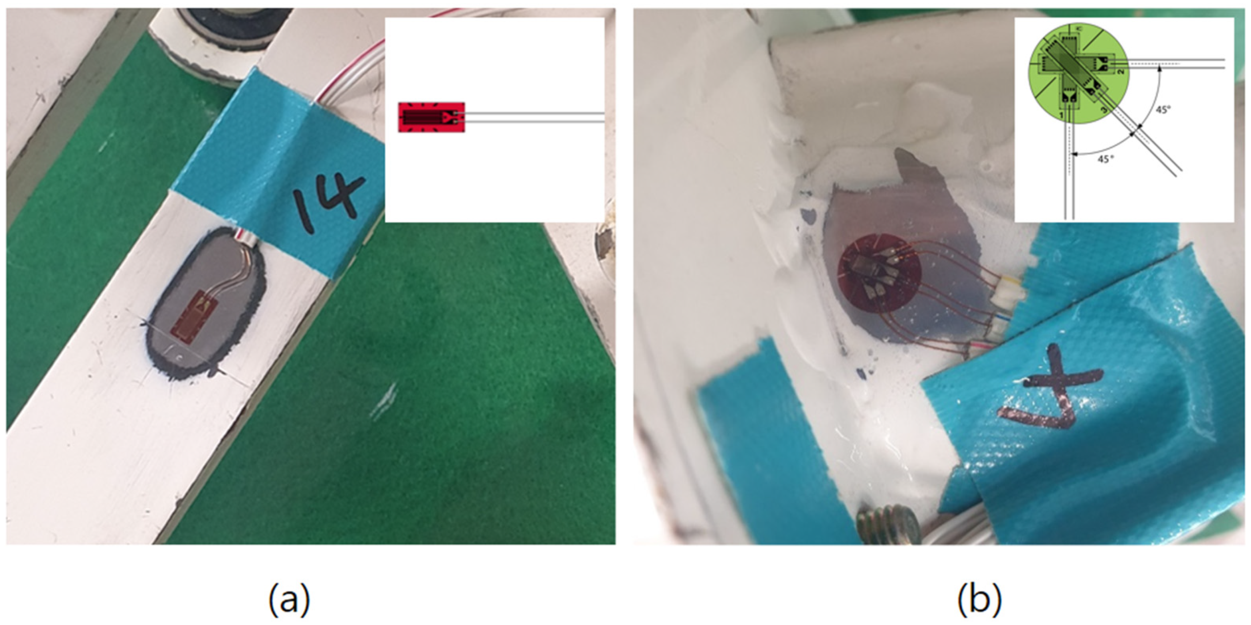
The load measurement system was constructed with strain sensors to measure the working load of the transplanting device. The sensor used in this study is strain gauge and there are two types of strain gauges according to the measurement spots, i.e., uniaxial strain gauge and triaxial strain gauge. The picture of each type of strain gauge is shown in Figure 4. A uniaxial strain gauge is suitable to measure the strain in a spot where the one main loading direction is clear, while the triaxial strain gauge is composed of three strain gauges that are suitable for the spot where the main loading direction is unknown.

Figure 4.
The type of strain gauge used in this study: (a) uniaxial strain gauge, (b) triaxial strain gauge.
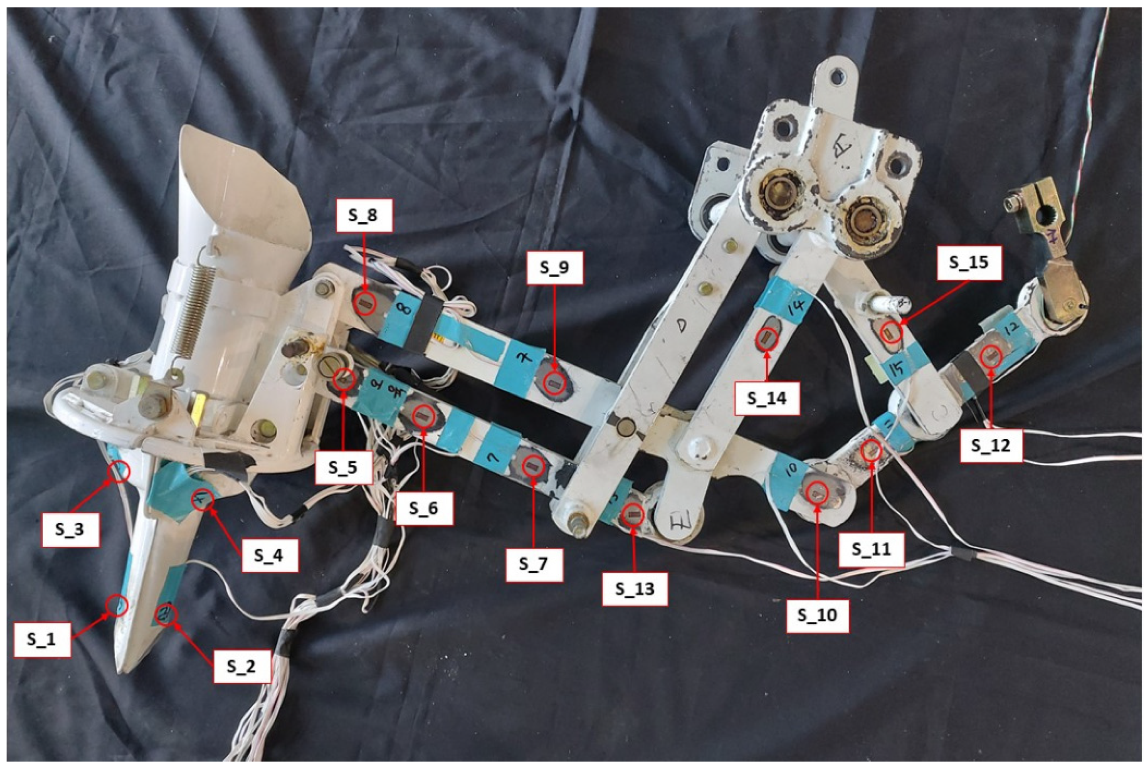
To record the load-time history, 15 strain gauges were attached to the selected spots on the transplanting device. We determined the location of the strain gauge installation by considering the loading path and the shape of each component. Thirteen uniaxial strain gauges (KFGS-5-350-C1-11 L10M3R, KYOWA) were used to measure the axial stress in the bottom side of the hopper (S_1 and S_2) and the link (S_5, S_6, S_7, S_8, S_9, S_10, S_11, S_12, S_13, S_14, and S_15). Two triaxial strain gauges or rosette (KFGS-1-350-D17-11 L5M3S, KYOWA) were attached to the upper side of the hopper (S_3 and S_4). Figure 5 shows the detailed location of the attached strain gauge.

Figure 5.
Location of attached strain gauge on transplanting device.
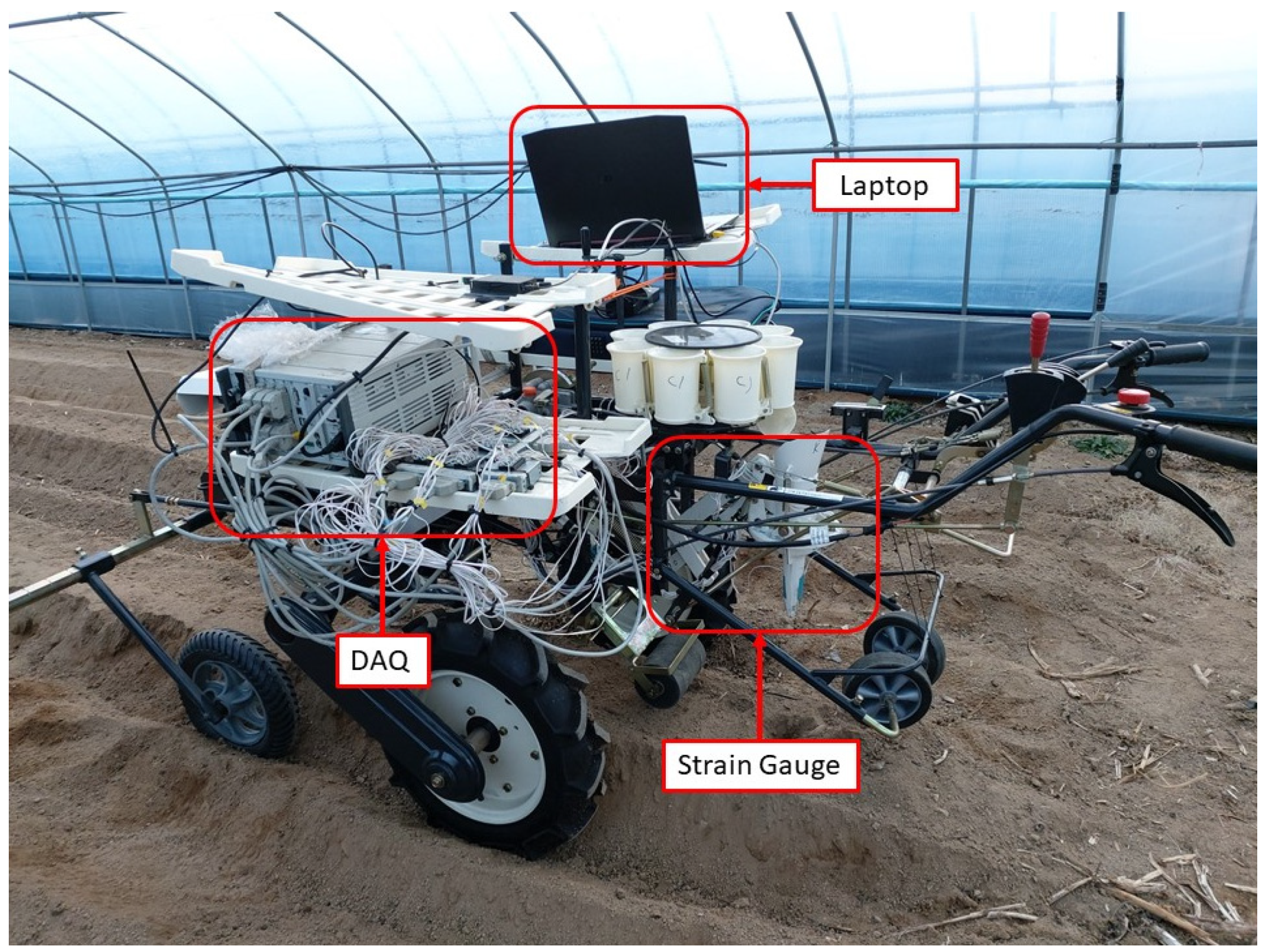
As a sensor, the strain gauge measures strain in the transplanting device, then the signal of the sensors was transmitted to the data acquisition device (DAQ) through the telemetry system and the data was saved in the laptop. The instrument setup for the measurement system is shown in Figure 6.

Figure 6.
The load measurement system on the 4-bar link type semi-automatic vegetable transplanter.
2.3. Work Conditions
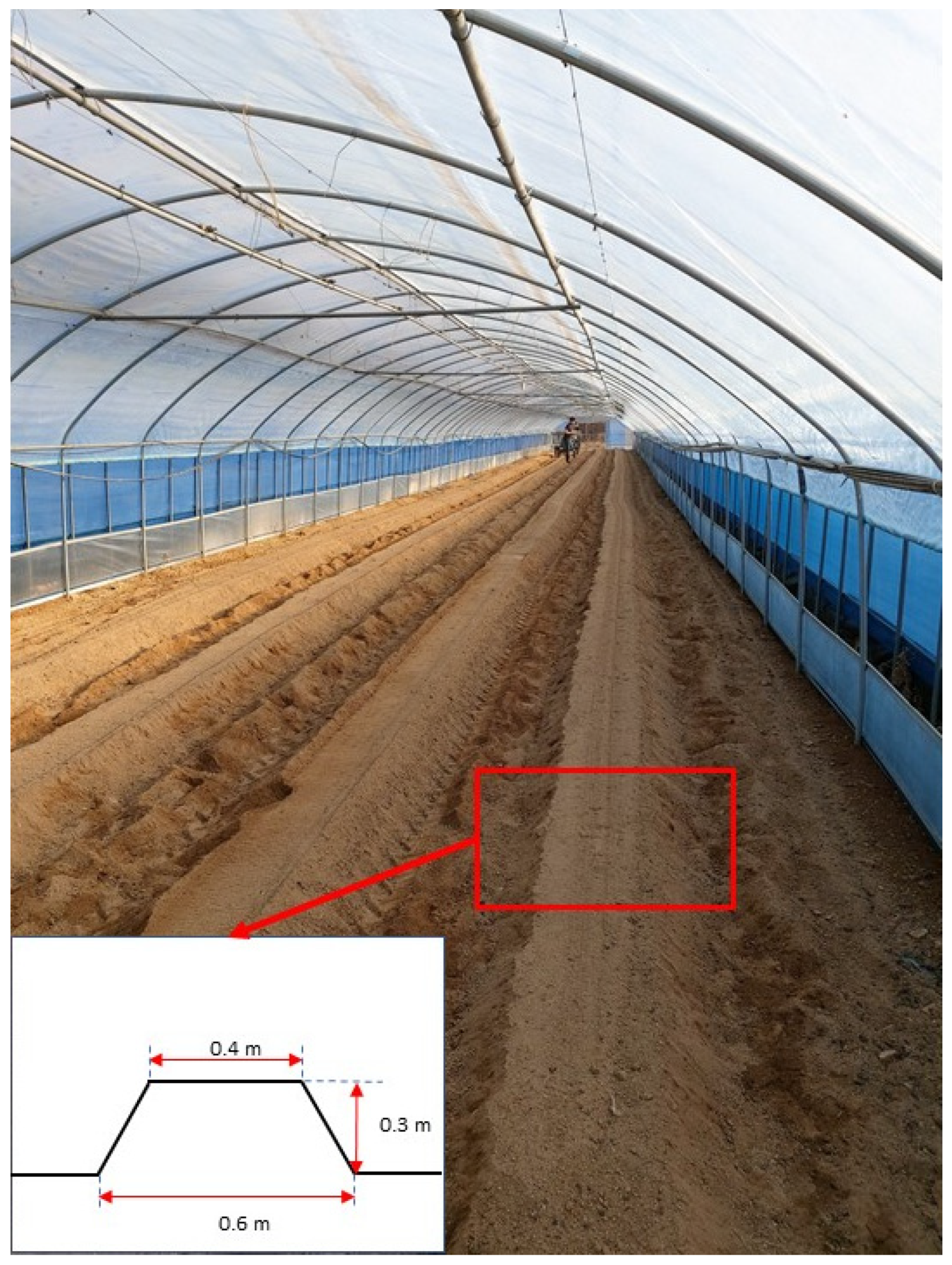
The load acting on the transplanting device depends on many factors, such as engine speed, soil conditions, planting distance, and planting depth. This research only considered the effect of engine speed and planting distance on transplanting device load. The soil condition factor is neglected because the soil used for transplanting vegetable seedlings has usually been plowed and harrowed so that it becomes very soft. The transplanting depth was also ignored because the variation of transplanting depth for vegetables is not too large, and the planting depth in this research was fixed to 70 mm. The field test site was located in Sinbuk-eup, Chuncheon, Gangwon Province in Korea, 37°56′24.0″ N and 127°46′59.1″ E with an altitude of 111.00 m.a.s.l. Figure 7 shows the experimental site has sandy soil type (sand 95%, silt 4%, clay 1%), and the water content was 20.1%, with the width and height of the ridge being 0.6 m and 0.3 m, respectively.

Figure 7.
A view of the experimental site.
There are 4 variations of the selected engine speed, namely 750, 1000, 1250, and 1500 rpm. The preliminary experiment shows if the engine speed was less than 750 rpm and above 1500 rpm, even when the throttle lever was fixed, the engine speed was irregularly changed, and it was not possible to maintain a constant rotation speed. Therefore, in this research, it is determined that the engine speed variation is from 750 rpm to 1500 rpm with an interval of 250 rpm. For planting distance variations, this machine has 10 shift stages of the transplanting transmission to determine the planting distance. The levels of planting distance are from level 1 (0.29 m) to level 10 (0.47 m) with an interval of 0.02 m. The field test was repeated 3 times for every working condition to improve the reliability of the data.
2.4. Analysis of Measured Data
Based on the type of strain gauge, there are two kinds of measured strain data. First, strain data from the uniaxial strain gauge. This measured axial strain data was converted into axial stress using Equation (1). The second is strain data from the triaxial strain gauge. Three directional strains can be measured by a triaxial strain gauge. From the strain of each direction, we can derive the representative stress values such as maximum and minimum principal stresses, Von-Mises stress, and maximum shear stress using Equations (2)–(5).
where, σ is the calculated axial stress, Pa; ε is the measured strain, mm mm−1; E is the modulus of elasticity, Pa; is the Von-Mises stress, Pa; is the maximum principal stress, Pa; is the minimum principal stress, Pa; τmax is the maximum shear stress, Pa; v is the Poisson’s ratio; εa is the measured strain in the horizontal direction in triaxial gauge, mm mm−1; εb is the measured strain in 45° direction in triaxial gauge, mm mm−1; εc is the measured strain in the vertical direction in triaxial gauge, mm mm−1.
2.4.1. Static Safety Factor
The static safety factor is the ratio between the maximum stress in the part and the yield strength of the material. Based on static safety analysis, the design is categorized into 2, namely safe and unsafe. The design is statically safe if the strength of the material is greater than the maximum stress that works in that part, so the static safety factor is above 1.0. The design is unsafe if the static safety factor is less than 1.0, because the strength of the material is smaller than the maximum stress in the part. The unsafe design means that the part may fail or not function properly.
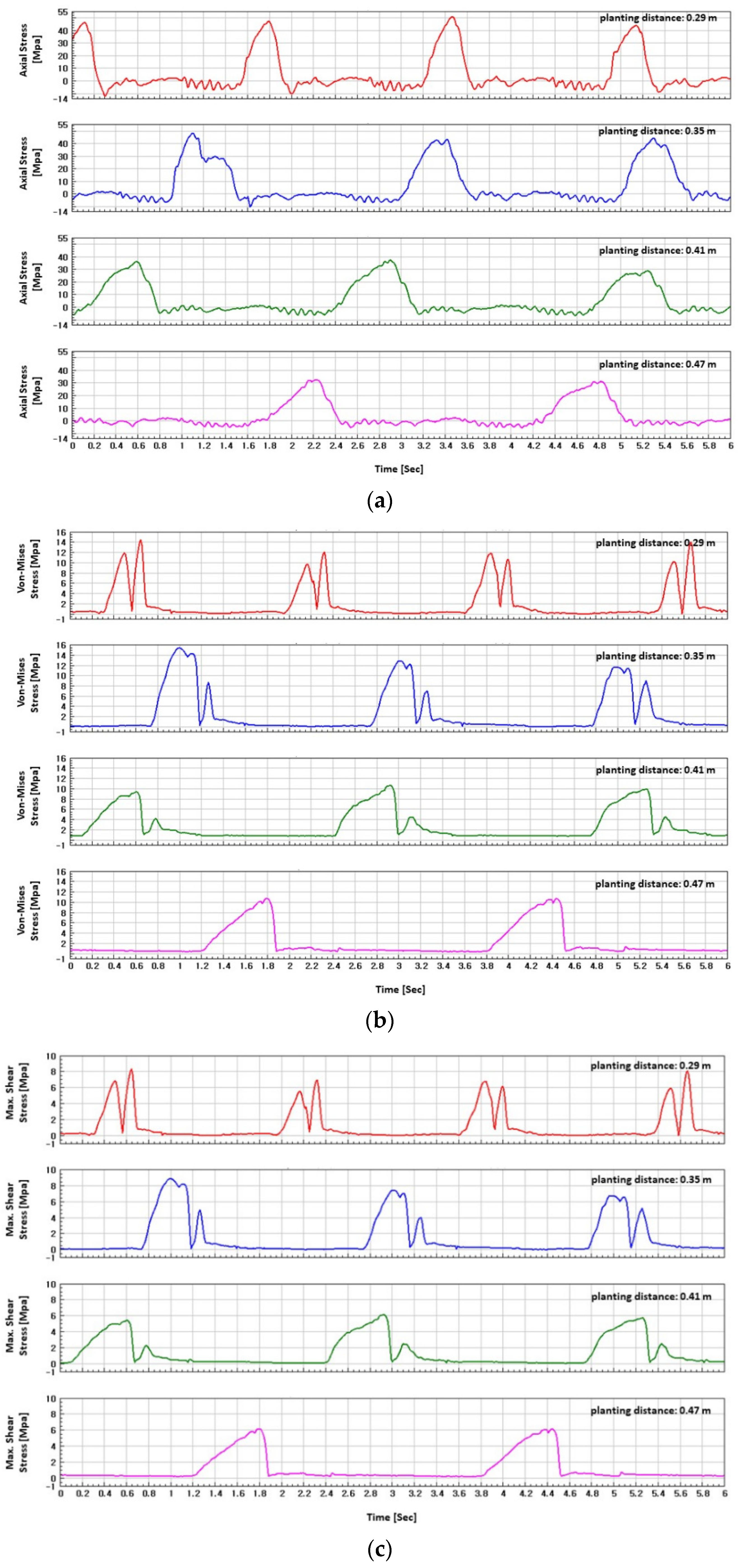
There are 3 types of stress as shown in Figure 8, so we calculated the static safety factor based on the maximum stress value from each type of stress. The maximum stress value is obtained from the highest peak because the time series stress data has so many peaks. The static safety factor based on the axial stress is calculated using Equation (6), while static safety factors based on the Von-Mises stress and maximum shear stress can be derived using Equations (7) and (8), respectively. The static safety of the design in this study was determined by the smallest value of the static safety factor for all 15 measurement spots and all variations of working conditions
where, SF is the static safety factor; Sy is the yield strength, Pa; Ssy is the yield strength in shear, Pa; is the maximum of the axial stress, Pa; ()max is the maximum of the Von-Mises stress, Pa; (τmax)max is the maximum shear stress.
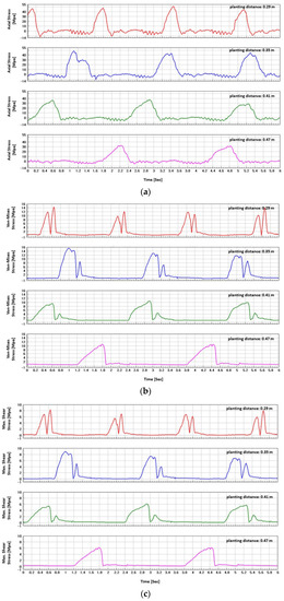
Figure 8.
The shape of time series stress data at 750 rpm of engine speed: (a) axial stress at S_8, (b) Von-Mises stress at S_3, (c) maximum shear stress at S_3.
2.4.2. Dynamic Safety (Fatigue Life)
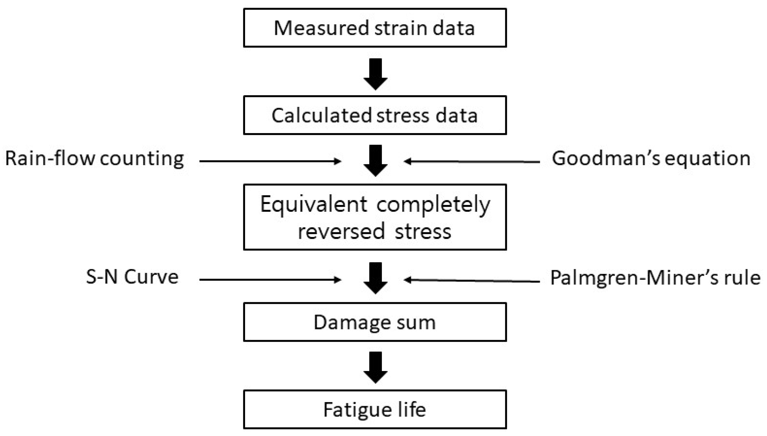
Design failure does not only occur if the maximum stress value in a certain area is greater than the yield strength of the material but can also be caused by fatigue failure. The fatigue failure can occur in parts subjected to cyclic loads. The transplanting device receives the cyclic loads when the transplanter is working, so a dynamic safety analysis is also needed. The fatigue life of the transplanting device was calculated using a procedure as shown in Figure 9.
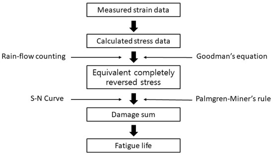
Figure 9.
The procedure of fatigue life calculation for the transplanting device.
The stress data were calculated from measured strain data. The calculated stress data were converted from the time domain to the frequency domain using the rain-flow counting method. The result of the rain-flow counting is the loading cycles for each mean stress and stress amplitude. The equivalent completely reversed stress was derived from mean stress and stress amplitude using Goodman’s equation (Equation (9)).
where, is the equivalent completely reversed stress, Pa; is the ultimate strength, Pa; is the stress amplitude, Pa; is the mean stress, Pa.
The damage sum was calculated by applying Palmgren–Miner’s rule of Equation (10) [13,21]. Total damage is derived from the sum of partial damage caused by all the loads acting on the part. Partial damage is the ratio between the actual applied loading cycles from the rain-flow counting result and the respective life cycles from the S-N curve for each equivalent completely reversed stress. When stress is less than the endurance limit, partial damage is 0, so fatigue failure does not occur regardless of the cycle. The fatigue life is calculated using the damage sum and the working time that caused the damage, as shown in Equation (11). The working time for each work condition in this research was 30 s.
where, D is the cumulative damage sum; is the actual applied cycles for equivalent completely reversed stress i, cycles; is the life cycles for equivalent completely reversed stress i, cycles; is the fatigue life, s; t is the working time which generates cumulative damage sum, s.
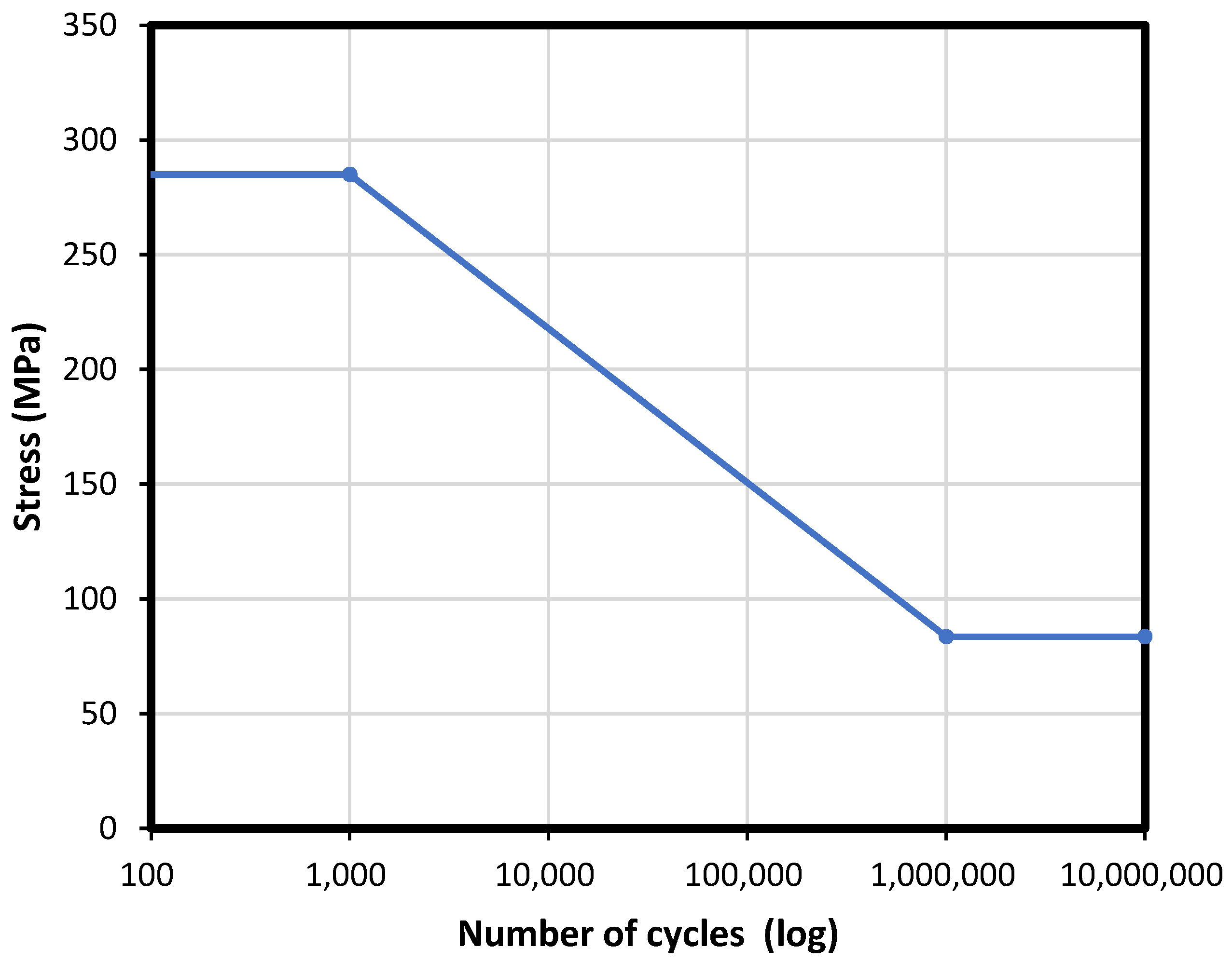
To obtain the S-N curve, the fatigue strengths for 103 cycles and 106 cycles were calculated by Equations (12) and (13), respectively, and then the S-N line was drawn, applying a linear relationship [18,21,33]. Based on the material properties of the transplanting device shown in Table 2, the calculated strengths for 103 and 106 cycles are 285 MPa and 83.51 MPa, respectively, and the S-N curve of the transplanting device is shown Figure 10.
where, is the fatigue strength of 106 cycles for the standard material, Pa; is the fatigue strength of 106 cycles for the actual component, Pa; is the fatigue strength of 103 cycles for the actual component, Pa; is the surface factor; is the gradient factor; is the load factor; is the temperature factor; is the reliability factor.

Figure 10.
An S-N curve for the transplanting device material.
3. Results and Discussion
3.1. The Stress Data
The calculated stress data were expressed in the time domain. Figure 8 shows the shape of stress data according to planting distance. The axial stress measured from the uniaxial strain gauge is shown in Figure 8a, while Figure 8b,c show Von-Mises stress and maximum shear stress measured from the triaxial strain gauge, respectively. The repetitive movement of the transplanting device during transplanting work makes the shapes of the stress data similar, which are a regular fluctuation pattern and has many peaks. The peak stress occurs when the transplanting hopper hits the ground. The period and magnitude of peak stress differed depending on the working conditions. The shorter planting distance has more peak stress than the longer planting distance.
3.2. Static Safety
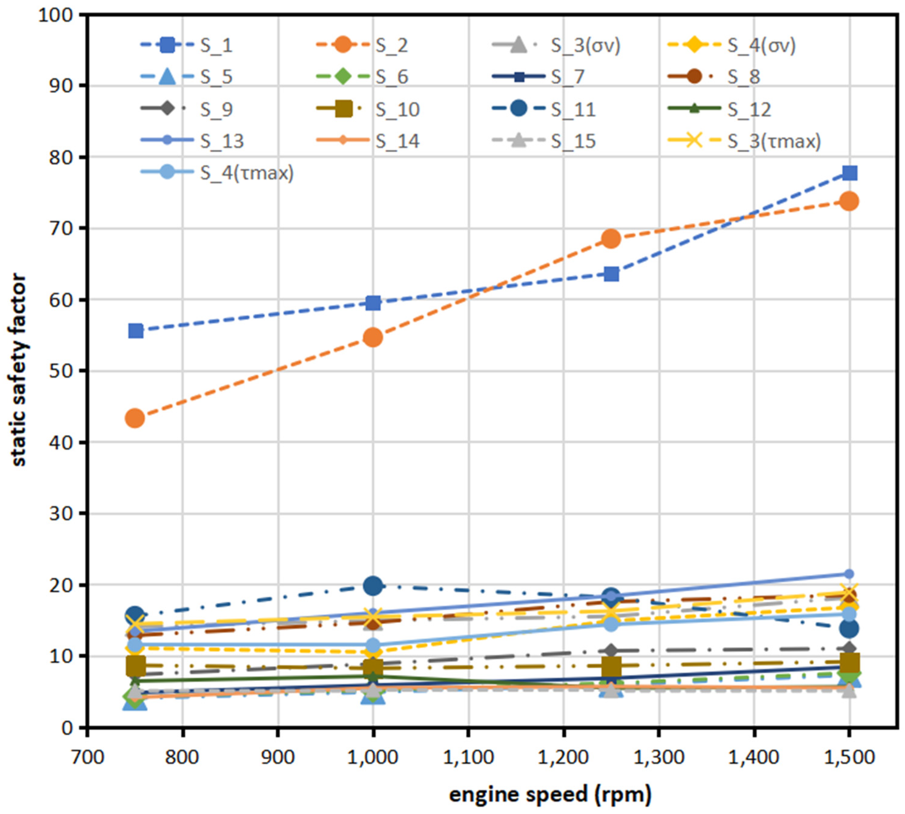
Table A1 shows the static safety factor for each location of the strain gauge under each working condition. The minimum static safety factor was 1.88 at the location of S_12, which is the link A, under the working condition of engine speed of 1250 rpm and a planting distance of 0.29 m. The location of S_12 has a lower static safety factor than other locations because link A is directly connected to the crank of the transplanting transmission and receives a high reaction force. Besides S_12, several locations have small static safety factor, such as S_5, S_6, S_7, S_14, and S_15. Nevertheless, the result shows that all locations have the static safety factor value of more than 1.0 for all working conditions. It means that the design of the transplanting device is statically safe.
Figure 11 shows the average static safety factor of the transplanting device for all planting distances according to the engine speed. The static safety factor shows a tendency to increase with the engine speed. The static safety factor was calculated using the strength of the material divided by the maximum stress in the transplanting device. The strength of the material is constant, so the maximum stress is inversely proportional to the static safety factor. It means that the increased engine speed makes the stress on the transplanting device decrease so the static safety factor increases. Figure 12 shows the average static safety factor of the transplanting device for all engine speeds according to the planting distance. Although there are some locations of a strain gauge that shows the fluctuation of the static safety factor value, it shows a tendency to increase with the planting distance. The shorter the planting distance, the stress will increase, and high peak stress will make the static safety factor smaller.
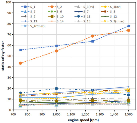
Figure 11.
The average static safety factor of the transplanting device according to the engine speed.
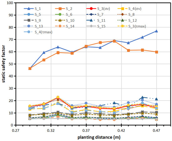
Figure 12.
The average static safety factor of the transplanting device according to the planting distance.
The maximum stress value in all locations of the strain gauge is lower than the strength of material, so the static safety factor value is more than 1. This result indicates that the crack will not occur because of high stress, but it can be caused by cycle loading. Therefore, the dynamic safety of fatigue life analysis must be conducted.
3.3. Dynamic Safety (Fatigue Life)
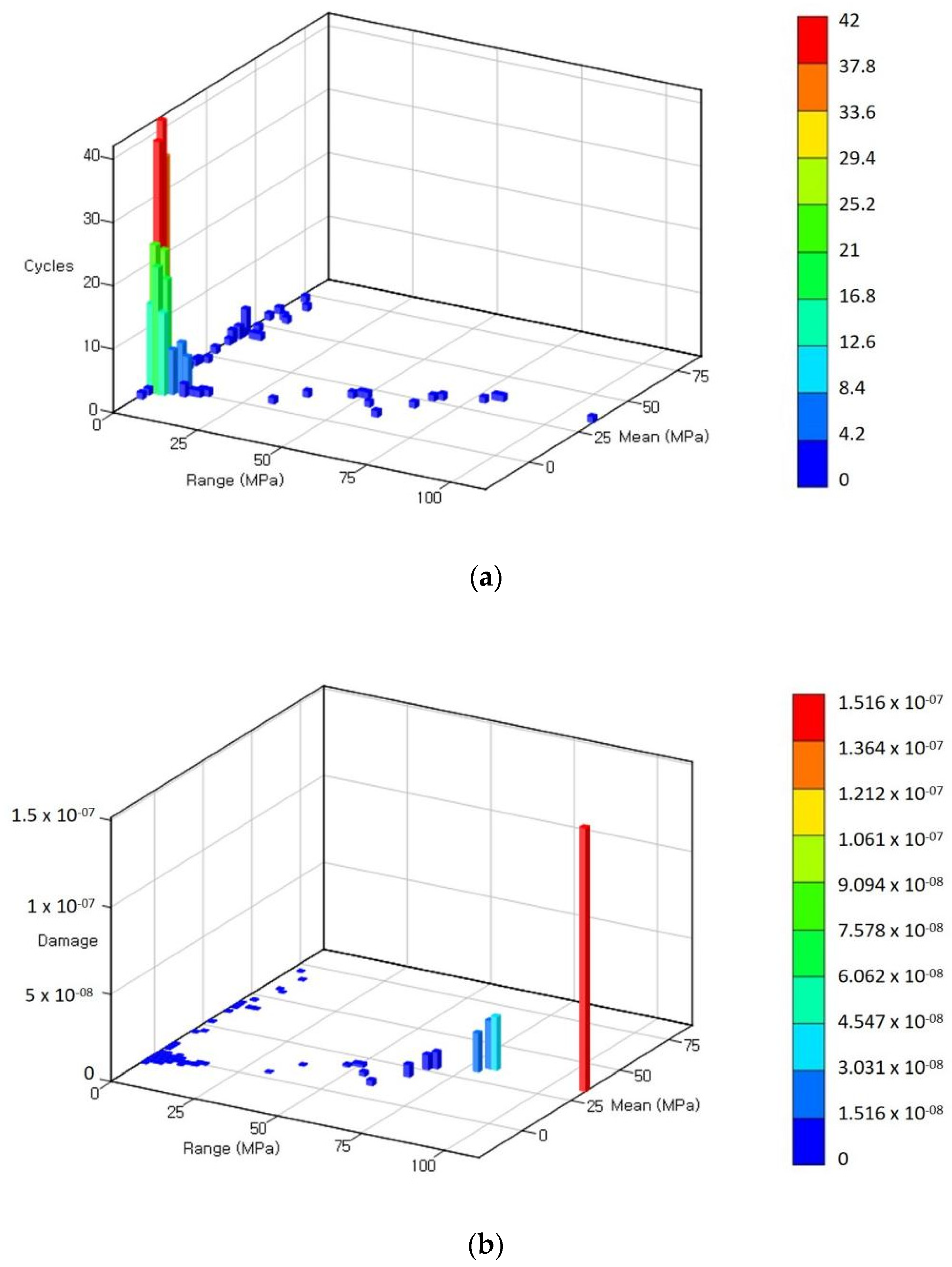
Table A2 shows the results of the fatigue life for each location of the strain gauge under each working condition. The minimum fatigue life was 49,153.3 h at the location of S_14 under the working condition of engine speed 750 rpm and planting distance of 0.35 m. The short fatigue life is caused by the high damage sum. Figure 13 shows the rain-flow counting result (Figure 13a) and damage sum (Figure 13b) for the S_14 strain gauge. From the rain-flow counting result histogram, it can be seen that only a few cycles of stress have a large range and mean, while the small stress and mean stress have so many cycles. However, most of the damage was caused by the stress, which has a large stress range and mean stress.
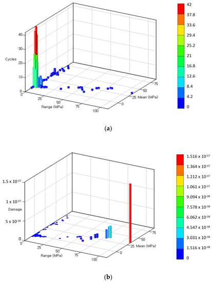
Figure 13.
(a) Rain-flow counting result and (b) Damage sum histogram of strain gauge S_14 when engine speed is 750 rpm and planting distance is 0.35 m.
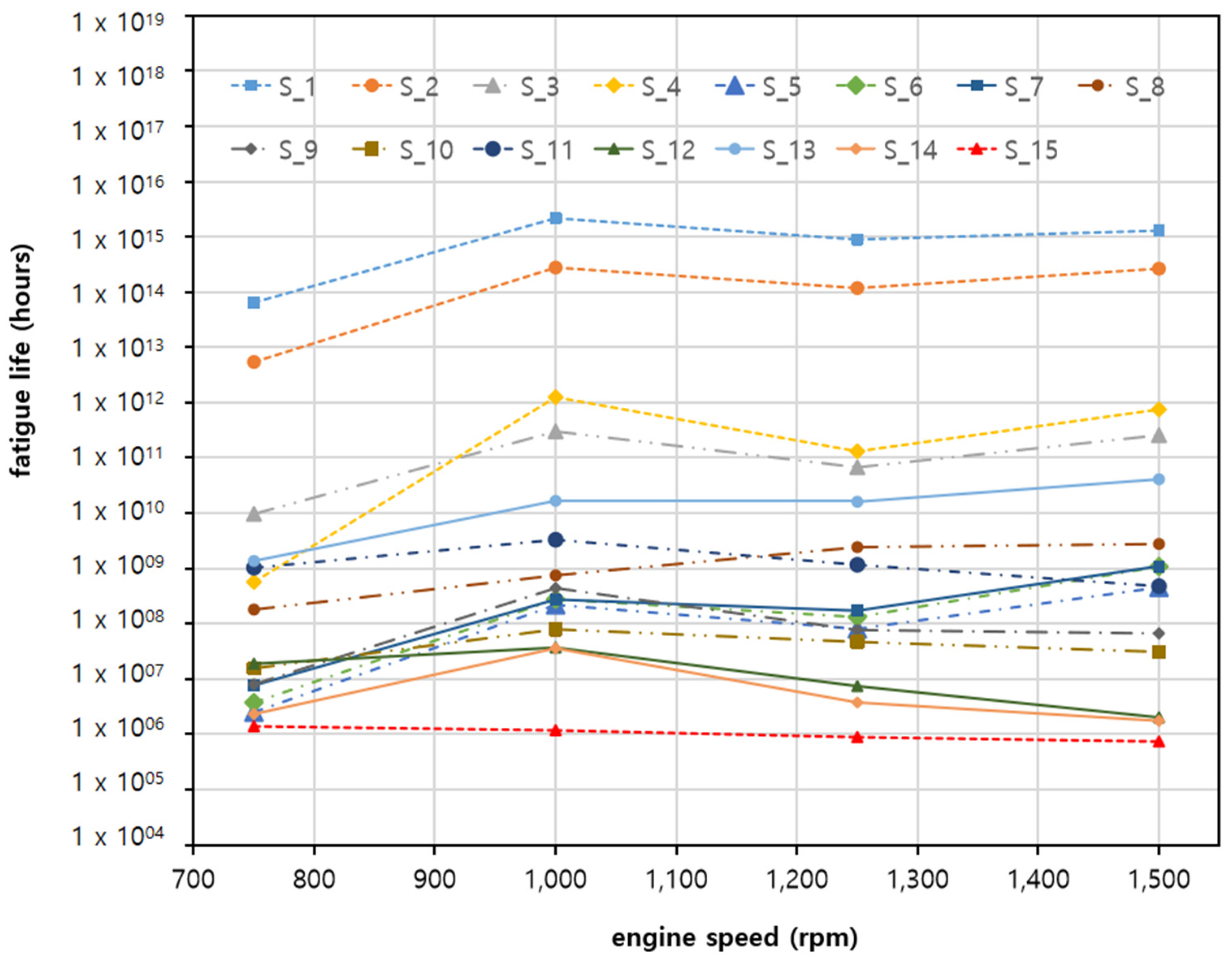
Figure 14 shows the average fatigue life of the transplanting device for all planting distances according to the engine speed. The fatigue life shows a tendency to increase with the engine speed. Increasing engine speed will make the stress on the transplanting device decrease and the fatigue life increase. Figure 15 shows the average fatigue life of the transplanting device for all engine speeds according to the planting distance. Although the results showed a little variation, in general, fatigue life tended to increase as the planting distance. The longer the planting distance, the fatigue life is increased because of the stress and frequency of movement cycles that can make damage decrease.
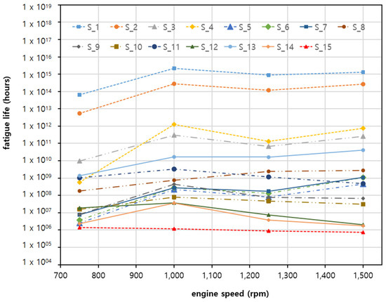
Figure 14.
The average fatigue life of the transplanting device is according to the engine speed.
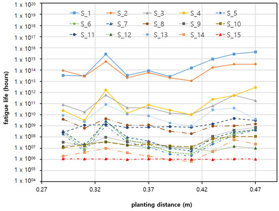
Figure 15.
The average fatigue life of the transplanting device according to the planting distance.
Table 3 shows the ANOVA result of fatigue life at location S_14, which is the minimum fatigue life spot, according to engine speed and planting distance. The fatigue life at location S_14 showed a significant difference according to engine speed at 5% of the significance level, while according to planting distance, the fatigue life at location S_14 did not show a significant difference at the same significance level. The interaction between engine speed and planting distance also did not show a significant effect on fatigue life.
Table 3.
The ANOVA result of fatigue life at location S_14 according to engine speed and planting distance.
The results show that increasing engine speed make the static safety factor and fatigue life of the transplanting device also increase. This result is different with the result from other research about safety analysis in other machines. Lee and Nam [21] conducted research about safety analysis in the tractor and the results showed that the fatigue life decreases as the engine speed increases. This is due to the difference in the transmission system in each machine. For the planting distance, the tendency is the same with other research [34].
From a literature review, the average annual usage time of vegetable transplanters in Korea is 25.5 h [29,35]. Considering the average annual usage time, the minimum fatigue life of the transplanting device was estimated to 1928 years at link D. This result is much greater when compared to the expected lifespan of the transplanting machine which is usually 10 years. Therefore, it can be concluded that the transplanting device of the 4-bar link semi-automatic vegetable transplanter can be used reliably for its expected lifetime.
4. Conclusions
A strain-based load measurement system was used to experimentally evaluate the static and dynamic safety of the transplanting device of a 4-bar link type semi-automatic vegetable transplanter. There are 13 uniaxial strain gauges and 2 triaxial strain gauges attached to the important spots to measure the strain working on the transplanting device. The field test was conducted under 4 levels of engine speeds (750, 1000, 1250, 1500 rpm) and 10 levels of planting distances (from 0.29 m to 0.47 m with an interval 0.02 m). The measured strain data was converted into stress values to analyze static safety factors and fatigue life of the transplanting device.
The main result of this research are as follows:
- The static safety factor was more than 1.0 for all locations and working conditions. The minimum static safety factor was 1.88 at the location of S_12 under the operating condition of an engine speed of 1250 rpm and a planting distance of 0.29 m.
- The minimum fatigue life was 49,153.3 h at the location of S_14 under the operating condition of an engine speed of 750 rpm and a planting distance of 0.35 m. Considering 25.5 h of annual usage time of vegetable transplanter, the minimum fatigue life of the transplanting device was 1928 years.
- The stress on the transplanting device tends to decrease when the engine speed and planning distance increases. Therefore, the static safety factor and the fatigue life are increased with the engine speed and planting distance.
- It can be concluded that the transplanting device understudy was designed to be safe statically and dynamically in the working environments. The link was directly connected to the crank of the transplanting transmission received the largest load and has the highest stress, so that part requires robust design.
In future research, we plan to do simulation tests to evaluate the static safety factor and fatigue life of the transplanting device of a 4-bar link type semi-automatic vegetable transplanter to save time and effort and make more reliable data.
Author Contributions
Data curation, formal analysis, and writing—original draft, M.S. and S.-J.H.; writing—review and editing, J.-S.N. All authors have read and agreed to the published version of the manuscript.
Funding
This work was supported by Korea Institute of Planning and Evaluation for Technology in Food, Agriculture and Forestry (IPET) through Agriculture, Food and Rural Affairs Convergence Technologies Program for Educating Creative Global Leader Program, funded by Ministry of Agriculture, Food and Rural Affairs (MAFRA) (716001-7). This work was also supported by Korea Institute of Planning and Evaluation for Technology in Food, Agriculture and Forestry (IPET) through Agriculture, Food and Rural Affairs Convergence Technologies Program for Educating Creative Global Leader, funded by Ministry of Agriculture, Food and Rural Affairs (MAFRA) (Project No. 320001-4), Republic of Korea.
Informed Consent Statement
Not applicable.
Conflicts of Interest
The authors declare no conflict of interest.
Appendix A
Table A1.
Static safety factor in every spot of strain gauge under each working condition.
Table A1.
Static safety factor in every spot of strain gauge under each working condition.
| Engine Speed (rpm) | Planting Distance (m) | Static Safety Factor | ||||||||||||||||
|---|---|---|---|---|---|---|---|---|---|---|---|---|---|---|---|---|---|---|
| S_1 | S_2 | S_3 (σv) | S_3 (τmax) | S_4 (σv) | S_4 (τmax) | S_5 | S_6 | S_7 | S_8 | S_9 | S_10 | S_11 | S_12 | S_13 | S_14 | S_15 | ||
| 750 | 0.29 | 45.46 | 39.23 | 16.00 | 16.18 | 12.60 | 11.07 | 4.17 | 4.41 | 4.96 | 13.13 | 8.34 | 10.20 | 14.58 | 6.50 | 12.22 | 4.11 | 5.37 |
| 0.31 | 55.67 | 47.99 | 19.53 | 19.91 | 15.32 | 14.95 | 5.43 | 5.71 | 6.44 | 16.75 | 9.42 | 9.72 | 23.77 | 8.38 | 17.32 | 5.79 | 5.31 | |
| 0.33 | 74.29 | 55.78 | 19.68 | 19.60 | 16.32 | 15.40 | 6.00 | 6.23 | 6.96 | 17.51 | 6.99 | 9.62 | 18.87 | 8.56 | 17.86 | 5.67 | 5.41 | |
| 0.35 | 34.21 | 30.38 | 11.01 | 11.41 | 9.20 | 10.64 | 2.95 | 3.15 | 3.57 | 9.79 | 5.96 | 7.58 | 9.10 | 4.36 | 9.68 | 2.58 | 4.93 | |
| 0.37 | 50.26 | 33.70 | 12.75 | 13.16 | 9.26 | 10.40 | 3.50 | 3.74 | 4.35 | 12.93 | 6.64 | 8.73 | 11.91 | 5.58 | 11.85 | 3.53 | 4.94 | |
| 0.39 | 64.55 | 51.09 | 14.51 | 15.02 | 11.00 | 13.72 | 3.58 | 3.85 | 4.49 | 14.20 | 8.35 | 10.06 | 13.66 | 6.52 | 13.16 | 3.69 | 4.93 | |
| 0.41 | 70.34 | 55.58 | 13.66 | 14.14 | 12.06 | 11.13 | 4.34 | 4.49 | 4.94 | 12.99 | 7.93 | 8.51 | 18.77 | 6.88 | 14.17 | 4.29 | 4.97 | |
| 0.43 | 40.35 | 24.23 | 10.21 | 10.91 | 6.42 | 7.10 | 2.88 | 3.22 | 3.64 | 8.58 | 5.32 | 6.39 | 9.61 | 4.91 | 10.40 | 3.27 | 4.92 | |
| 0.45 | 47.85 | 42.66 | 11.21 | 11.80 | 8.86 | 10.62 | 3.78 | 3.98 | 4.45 | 10.26 | 6.62 | 7.62 | 17.82 | 6.53 | 13.07 | 4.15 | 5.14 | |
| 0.47 | 73.07 | 52.40 | 12.08 | 12.53 | 9.57 | 10.63 | 3.84 | 4.03 | 4.48 | 12.39 | 7.83 | 8.16 | 17.77 | 6.28 | 14.43 | 4.52 | 4.90 | |
| 1000 | 0.29 | 62.05 | 49.06 | 11.35 | 12.02 | 8.35 | 8.44 | 3.43 | 3.68 | 4.33 | 11.17 | 5.58 | 6.14 | 12.61 | 7.14 | 11.16 | 4.47 | 5.46 |
| 0.31 | 55.48 | 43.06 | 19.66 | 19.67 | 13.99 | 14.60 | 4.55 | 4.88 | 5.60 | 17.81 | 8.08 | 9.36 | 19.08 | 8.22 | 13.50 | 5.48 | 5.32 | |
| 0.33 | 65.74 | 60.01 | 20.01 | 20.21 | 9.75 | 8.98 | 5.31 | 5.72 | 6.85 | 18.44 | 8.45 | 9.16 | 23.07 | 10.22 | 16.06 | 7.76 | 5.25 | |
| 0.35 | 72.83 | 61.42 | 15.52 | 15.99 | 8.12 | 7.39 | 5.03 | 5.33 | 6.09 | 15.66 | 8.61 | 8.49 | 19.12 | 8.81 | 18.67 | 6.55 | 5.23 | |
| 0.37 | 56.12 | 68.93 | 11.95 | 12.43 | 6.12 | 5.61 | 4.53 | 4.85 | 5.53 | 12.41 | 7.60 | 6.89 | 16.71 | 7.62 | 15.75 | 4.92 | 5.17 | |
| 0.39 | 55.28 | 61.91 | 11.59 | 11.98 | 7.16 | 6.56 | 4.48 | 4.72 | 5.30 | 13.11 | 8.29 | 7.19 | 18.45 | 7.75 | 15.77 | 4.59 | 5.14 | |
| 0.41 | 62.83 | 60.70 | 13.65 | 14.01 | 8.28 | 7.37 | 4.41 | 4.67 | 5.26 | 10.83 | 7.54 | 8.17 | 16.97 | 6.79 | 13.98 | 4.29 | 4.95 | |
| 0.43 | 63.53 | 56.05 | 10.13 | 10.62 | 6.93 | 6.45 | 3.54 | 3.82 | 4.49 | 9.20 | 6.80 | 6.48 | 15.78 | 6.37 | 12.44 | 3.91 | 4.85 | |
| 0.45 | 55.60 | 46.29 | 18.25 | 18.82 | 17.23 | 27.88 | 6.73 | 6.95 | 7.67 | 18.54 | 13.70 | 10.29 | 28.01 | 6.28 | 21.95 | 6.54 | 5.11 | |
| 0.47 | 45.41 | 39.05 | 17.09 | 18.70 | 19.20 | 21.42 | 7.01 | 7.08 | 7.57 | 19.21 | 13.80 | 10.24 | 28.11 | 2.07 | 20.67 | 6.32 | 5.50 | |
| 1250 | 0.29 | 34.39 | 33.23 | 15.97 | 16.87 | 16.65 | 20.83 | 5.53 | 5.89 | 6.76 | 18.64 | 8.66 | 7.87 | 18.95 | 1.88 | 16.84 | 7.38 | 5.35 |
| 0.31 | 58.13 | 57.35 | 15.33 | 15.85 | 13.06 | 13.41 | 5.81 | 6.15 | 6.92 | 18.72 | 10.94 | 8.67 | 12.55 | 6.73 | 17.40 | 5.67 | 5.31 | |
| 0.33 | 46.91 | 54.78 | 17.99 | 18.47 | 16.83 | 16.21 | 6.28 | 6.54 | 7.28 | 19.09 | 10.98 | 8.91 | 12.64 | 6.22 | 17.75 | 5.69 | 5.22 | |
| 0.35 | 62.32 | 60.46 | 10.38 | 11.07 | 9.58 | 8.56 | 4.43 | 4.67 | 5.15 | 15.82 | 8.41 | 6.40 | 15.19 | 5.53 | 12.32 | 4.47 | 5.05 | |
| 0.37 | 58.69 | 80.42 | 15.51 | 16.30 | 15.22 | 13.66 | 5.99 | 6.26 | 6.90 | 17.79 | 11.85 | 8.80 | 19.32 | 6.25 | 16.80 | 6.28 | 5.12 | |
| 0.39 | 50.70 | 82.18 | 11.55 | 12.36 | 10.92 | 9.72 | 5.50 | 5.67 | 6.18 | 16.49 | 9.82 | 6.93 | 17.23 | 5.41 | 16.42 | 4.33 | 4.96 | |
| 0.41 | 67.85 | 88.82 | 14.82 | 15.64 | 14.30 | 12.79 | 5.67 | 5.83 | 6.33 | 16.78 | 10.27 | 8.20 | 22.91 | 5.56 | 17.58 | 5.02 | 5.02 | |
| 0.43 | 75.32 | 77.35 | 25.43 | 26.29 | 25.48 | 24.39 | 7.96 | 8.49 | 9.91 | 18.24 | 13.64 | 13.45 | 19.67 | 5.73 | 32.11 | 8.73 | 4.96 | |
| 0.45 | 89.57 | 70.81 | 16.44 | 17.25 | 15.55 | 14.19 | 6.48 | 6.68 | 7.35 | 17.41 | 12.06 | 9.49 | 22.61 | 5.88 | 20.43 | 5.24 | 5.04 | |
| 0.47 | 92.23 | 79.36 | 11.79 | 12.49 | 11.32 | 10.09 | 5.31 | 5.36 | 5.67 | 16.81 | 10.37 | 7.32 | 20.77 | 5.40 | 16.07 | 4.02 | 4.87 | |
| 1500 | 0.29 | 42.67 | 63.51 | 16.55 | 17.32 | 14.79 | 13.64 | 7.33 | 7.58 | 8.40 | 19.68 | 10.23 | 8.09 | 8.67 | 6.01 | 20.32 | 5.23 | 5.19 |
| 0.31 | 67.96 | 64.63 | 12.64 | 13.21 | 11.91 | 11.16 | 5.46 | 5.68 | 6.37 | 16.92 | 8.93 | 7.08 | 9.38 | 5.28 | 15.24 | 4.74 | 5.33 | |
| 0.33 | 68.14 | 66.41 | 31.49 | 32.93 | 28.77 | 29.55 | 14.46 | 14.61 | 15.83 | 27.11 | 15.74 | 11.08 | 16.32 | 6.29 | 39.57 | 8.00 | 5.07 | |
| 0.35 | 68.91 | 82.72 | 18.62 | 19.71 | 16.21 | 14.76 | 7.78 | 8.26 | 9.50 | 20.46 | 11.75 | 8.97 | 11.88 | 6.03 | 22.58 | 6.36 | 5.19 | |
| 0.37 | 90.80 | 75.13 | 20.76 | 21.66 | 19.71 | 18.24 | 7.79 | 8.30 | 9.60 | 20.62 | 13.67 | 10.80 | 10.42 | 5.73 | 27.02 | 5.48 | 5.19 | |
| 0.39 | 82.92 | 74.57 | 16.81 | 17.43 | 14.04 | 13.85 | 5.40 | 5.77 | 6.54 | 15.74 | 10.48 | 8.87 | 13.68 | 5.53 | 15.96 | 5.14 | 5.03 | |
| 0.41 | 75.16 | 69.72 | 10.46 | 11.00 | 9.89 | 8.80 | 4.63 | 4.76 | 5.17 | 12.94 | 8.37 | 6.42 | 13.94 | 4.89 | 12.72 | 4.05 | 4.95 | |
| 0.43 | 89.74 | 86.89 | 16.61 | 17.11 | 17.65 | 15.93 | 6.34 | 6.70 | 7.26 | 16.13 | 10.75 | 8.79 | 13.49 | 5.27 | 18.23 | 5.32 | 4.94 | |
| 0.45 | 94.20 | 85.58 | 21.66 | 22.28 | 20.95 | 19.58 | 7.61 | 8.13 | 9.12 | 19.21 | 10.45 | 11.38 | 22.18 | 6.00 | 26.31 | 6.68 | 5.02 | |
| 0.47 | 96.74 | 68.33 | 15.87 | 16.30 | 13.84 | 12.81 | 5.93 | 6.01 | 6.43 | 15.87 | 9.62 | 10.06 | 18.40 | 5.44 | 16.74 | 4.03 | 4.95 | |
Table A2.
Fatigue life in every spot of strain gauge under each working condition.
Table A2.
Fatigue life in every spot of strain gauge under each working condition.
| Engine Speed (rpm) | Planting Distance (m) | Fatigue Life (Hours) | ||||||||||||||
|---|---|---|---|---|---|---|---|---|---|---|---|---|---|---|---|---|
| S_1 | S_2 | S_3 | S_4 | S_5 | S_6 | S_7 | S_8 | S_9 | S_10 | S_11 | S_12 | S_13 | S_14 | S_15 | ||
| 750 | 0.29 | 1.54 × 10¹² | 1.70 × 10¹² | 5.85 × 10⁹ | 9.96 × 10⁸ | 9.36 × 10⁵ | 1.43 × 10⁶ | 3.18 × 10⁶ | 9.32 × 10⁷ | 3.99 × 10⁶ | 1.09 × 10⁷ | 6.72 × 10⁸ | 1.41 × 10⁷ | 2.95 × 10⁸ | 6.89 × 10⁵ | 1.58 × 10⁶ |
| 0.31 | 5.61 × 10¹³ | 2.53 × 10¹³ | 3.86 × 10¹⁰ | 7.25 × 10⁸ | 1.04 × 10⁷ | 1.63 × 10⁷ | 3.37 × 10⁷ | 8.45 × 10⁸ | 3.21 × 10⁷ | 4.07 × 10⁷ | 3.00 × 10⁹ | 5.52 × 10⁷ | 5.98 × 10⁹ | 1.29 × 10⁷ | 1.47 × 10⁶ | |
| 0.33 | 1.67 × 10¹⁴ | 1.31 × 10¹³ | 2.6 × 10¹⁰ | 7.36 × 10⁸ | 7.99 × 10⁶ | 1.14 × 10⁷ | 2.17 × 10⁷ | 4.77 × 10⁸ | 1.32 × 10⁷ | 3.39 × 10⁷ | 2.08 × 10⁹ | 4.18 × 10⁷ | 3.82 × 10⁹ | 4.01 × 10⁶ | 1.68 × 10⁶ | |
| 0.35 | 1.39 × 10¹¹ | 8.58 × 10¹⁰ | 4.99 × 10⁸ | 2.62 × 10⁸ | 1.50 × 10⁵ | 2.38 × 10⁵ | 5.70 × 10⁵ | 1.18 × 10⁷ | 7.69 × 10⁵ | 2.53 × 10⁶ | 2.11 × 10⁷ | 1.71 × 10⁶ | 5.96 × 10⁷ | 4.92 × 10⁴ | 1.14 × 10⁶ | |
| 0.37 | 2.23 × 10¹² | 4.11 × 10¹¹ | 3.32 × 10⁹ | 4.49 × 10⁸ | 8.03 × 10⁵ | 1.31 × 10⁶ | 3.31 × 10⁶ | 7.06 × 10⁷ | 4.06 × 10⁶ | 1.08 × 10⁷ | 2.40 × 10⁸ | 9.75 × 10⁶ | 4.67 × 10⁸ | 4.90 × 10⁵ | 1.37 × 10⁶ | |
| 0.39 | 2.66 × 10¹³ | 2.89 × 10¹² | 8.90 × 10⁹ | 1.08 × 10⁸ | 1.57 × 10⁶ | 2.30 × 10⁶ | 4.93 × 10⁶ | 1.03 × 10⁸ | 6.65 × 10⁶ | 1.36 × 10⁷ | 1.01 × 10⁹ | 2.14 × 10⁷ | 1.10 × 10⁹ | 1.03 × 10⁶ | 1.37 × 10⁶ | |
| 0.41 | 9.96 × 10¹³ | 3.32 × 10¹² | 7.48 × 10⁹ | 4.28 × 10⁸ | 1.40 × 10⁶ | 2.02 × 10⁶ | 4.25 × 10⁶ | 1.02 × 10⁸ | 8.56 × 10⁶ | 1.61 × 10⁷ | 9.42 × 10⁸ | 2.09 × 10⁷ | 9.23 × 10⁸ | 1.13 × 10⁶ | 1.39 × 10⁶ | |
| 0.43 | 2.53 × 10¹² | 3.35 × 10¹⁰ | 6.79 × 10⁸ | 1.30 × 10⁸ | 1.16 × 10⁵ | 1.92 × 10⁵ | 4.65 × 10⁵ | 7.31 × 10⁶ | 5.88 × 10⁵ | 2.13 × 10⁶ | 2.97 × 10⁷ | 2.70 × 10⁶ | 4.32 × 10⁷ | 1.71 × 10⁵ | 1.11 × 10⁶ | |
| 0.45 | 2.63 × 10¹⁴ | 1.69 × 10¹² | 3.16 × 10⁹ | 3.87 × 10⁸ | 9.29 × 10⁵ | 1.30 × 10⁶ | 2.59 × 10⁶ | 5.07 × 10⁷ | 5.66 × 10⁶ | 1.28 × 10⁷ | 1.49 × 10⁹ | 1.17 × 10⁷ | 5.69 × 10⁸ | 1.61 × 10⁵ | 1.43 × 10⁶ | |
| 0.47 | 2.62 × 10¹³ | 5.66 × 10¹² | 2.22 × 10⁹ | 4.87 × 10⁸ | 7.47 × 10⁵ | 1.01 × 10⁶ | 1.93 × 10⁶ | 4.21 × 10⁷ | 4.60 × 10⁶ | 1.23 × 10⁷ | 8.29 × 10⁸ | 8.90 × 10⁶ | 4.17 × 10⁸ | 1.13 × 10⁶ | 1.39 × 10⁶ | |
| 1000 | 0.29 | 5.23 × 10¹² | 2.45 × 10¹² | 1.19 × 10⁹ | 2.54 × 10⁸ | 2.10 × 10⁵ | 3.46 × 10⁵ | 9.53 × 10⁵ | 3.37 × 10⁷ | 7.97 × 10⁵ | 2.82 × 10⁶ | 9.35 × 10⁷ | 5.81 × 10⁶ | 1.22 × 10⁸ | 2.06 × 10⁵ | 1.42 × 10⁶ |
| 0.31 | 1.03 × 10¹³ | 2.01 × 10¹² | 1.59 × 10¹⁰ | 3.16 × 10⁸ | 1.52 × 10⁶ | 2.41 × 10⁶ | 6.01 × 10⁶ | 2.56 × 10⁸ | 7.50 × 10⁶ | 1.64 × 10⁷ | 1.28 × 10⁹ | 3.66 × 10⁷ | 7.27 × 10⁸ | 1.87 × 10⁶ | 1.35 × 10⁶ | |
| 0.33 | 1.85 × 10¹⁴ | 6.70 × 10¹³ | 5.84 × 10¹⁰ | 1.71 × 10⁸ | 1.75 × 10⁷ | 3.07 × 10⁷ | 7.22 × 10⁷ | 1.01 × 10⁹ | 4.04 × 10⁷ | 5.56 × 10⁷ | 2.65 × 10⁹ | 1.06 × 10⁸ | 1.50 × 10¹⁰ | 2.87 × 10⁷ | 1.30 × 10⁶ | |
| 0.35 | 1.26 × 10¹⁴ | 3.60 × 10¹³ | 8.71 × 10¹⁰ | 1.87 × 10⁸ | 1.06 × 10⁷ | 1.88 × 10⁷ | 4.50 × 10⁷ | 9.08 × 10⁸ | 4.02 × 10⁷ | 4.09 × 10⁷ | 2.33 × 10⁹ | 7.61 × 10⁷ | 1.28 × 10¹⁰ | 1.30 × 10⁷ | 1.25 × 10⁶ | |
| 0.37 | 2.30 × 10¹³ | 9.89 × 10¹² | 1.21 × 10¹⁰ | 1.06 × 10⁸ | 1.37 × 10⁶ | 2.20 × 10⁶ | 5.23 × 10⁶ | 1.69 × 10⁸ | 5.38 × 10⁶ | 1.33 × 10⁷ | 9.77 × 10⁸ | 2.54 × 10⁷ | 9.81 × 10⁸ | 1.18 × 10⁶ | 1.20 × 10⁶ | |
| 0.39 | 1.25 × 10¹³ | 2.66 × 10¹³ | 3.86 × 10¹⁰ | 2.44 × 10⁸ | 1.91 × 10⁶ | 2.93 × 10⁶ | 6.69 × 10⁶ | 1.33 × 10⁸ | 8.17 × 10⁶ | 1.70 × 10⁷ | 1.16 × 10⁹ | 2.88 × 10⁷ | 1.41 × 10⁹ | 1.18 × 10⁶ | 1.09 × 10⁶ | |
| 0.41 | 1.46 × 10¹³ | 4.19 × 10¹² | 1.42 × 10¹⁰ | 1.06 × 10⁸ | 1.34 × 10⁶ | 1.85 × 10⁶ | 3.71 × 10⁶ | 1.18 × 10⁸ | 5.49 × 10⁶ | 9.73 × 10⁶ | 8.22 × 10⁸ | 1.42 × 10⁷ | 7.74 × 10⁸ | 6.22 × 10⁵ | 9.89 × 10⁵ | |
| 0.43 | 3.26 × 10¹³ | 3.29 × 10¹² | 3.14 × 10⁹ | 9.35 × 10⁸ | 5.24 × 10⁵ | 7.64 × 10⁵ | 1.67 × 10⁶ | 3.02 × 10⁷ | 2.52 × 10⁶ | 6.03 × 10⁶ | 5.14 × 10⁸ | 9.60 × 10⁶ | 2.87 × 10⁸ | 3.58 × 10⁵ | 9.35 × 10⁵ | |
| 0.45 | 5.23 × 10¹⁵ | 1.28 × 10¹⁵ | 2.1 × 10¹² | 1.53 × 10¹² | 5.06 × 10⁸ | 6.79 × 10⁸ | 9.02 × 10⁸ | 9.68 × 10⁶ | 1.45 × 10⁹ | 2.26 × 10⁸ | 1.29 × 10¹⁰ | 3.95 × 10⁷ | 1.23 × 10¹¹ | 2.18 × 10⁸ | 1.13 × 10⁶ | |
| 0.47 | 1.60 × 10¹⁶ | 1.34 × 10¹⁵ | 7.11 × 10¹¹ | 1.1 × 10¹³ | 1.66 × 10⁹ | 2.03 × 10⁹ | 1.70 × 10⁹ | 4.82 × 10⁹ | 2.84 × 10⁹ | 4.05 × 10⁸ | 1.03 × 10¹⁰ | 2.72 × 10⁷ | 1.21E+10 | 9.32E+07 | 1.15 × 10⁶ | |
| 1250 | 0.29 | 1.20 × 10¹⁴ | 3.43 × 10¹⁴ | 2.87 × 10¹¹ | 7.16 × 10¹⁰ | 6.70 × 10⁸ | 1.11 × 10⁹ | 1.31 × 10⁹ | 1.40 × 10¹⁰ | 1.17 × 10⁸ | 2.41 × 10⁷ | 2.45 × 10⁸ | 4.10 × 10⁷ | 3.07 × 10¹⁰ | 6.82 × 10⁶ | 8.49 × 10⁵ |
| 0.31 | 2.79 × 10¹³ | 7.37 × 10¹³ | 8.71 × 10⁹ | 5.84 × 10⁹ | 6.20 × 10⁶ | 9.45 × 10⁶ | 1.75 × 10⁷ | 1.01 × 10⁹ | 2.18 × 10⁷ | 1.40 × 10⁷ | 2.82 × 10⁸ | 6.32 × 10⁶ | 2.14 × 10⁹ | 1.68 × 10⁶ | 8.71 × 10⁵ | |
| 0.33 | 2.32 × 10¹³ | 2.12 × 10¹² | 1.59 × 10¹⁰ | 2.91 × 10¹⁰ | 1.19 × 10⁷ | 1.78 × 10⁷ | 3.24 × 10⁷ | 2.27 × 10⁹ | 3.16 × 10⁷ | 1.93 × 10⁷ | 4.52 × 10⁸ | 4.19 × 10⁶ | 3.88 × 10⁹ | 3.30 × 10⁶ | 8.28 × 10⁵ | |
| 0.35 | 3.53 × 10¹² | 5.87 × 10¹² | 3.91 × 10⁹ | 4.73 × 10⁹ | 7.79 × 10⁵ | 1.14 × 10⁶ | 2.27 × 10⁶ | 2.38 × 10⁸ | 5.49 × 10⁶ | 7.02 × 10⁶ | 2.49 × 10⁸ | 1.35 × 10⁶ | 2.46 × 10⁸ | 3.05 × 10⁵ | 7.83 × 10⁵ | |
| 0.37 | 2.13 × 10¹⁴ | 1.01 × 10¹⁴ | 5.46 × 10¹⁰ | 1.25 × 10¹¹ | 1.02 × 10⁷ | 1.58 × 10⁷ | 3.06 × 10⁷ | 1.30 × 10⁹ | 3.88 × 10⁷ | 3.20 × 10⁷ | 1.21 × 10⁹ | 4.71 × 10⁶ | 3.86 × 10⁹ | 2.32 × 10⁶ | 1.02 × 10⁶ | |
| 0.39 | 5.61 × 10¹³ | 3.53 × 10¹³ | 2.37 × 10¹⁰ | 3.97 × 10¹⁰ | 4.05 × 10⁶ | 6.12 × 10⁶ | 1.22 × 10⁷ | 5.43 × 10⁸ | 1.72 × 10⁷ | 1.78 × 10⁷ | 8.16 × 10⁸ | 2.74 × 10⁶ | 2.58 × 10⁹ | 8.46 × 10⁵ | 9.12 × 10⁵ | |
| 0.41 | 5.17 × 10¹⁴ | 3.15 × 10¹³ | 1.83 × 10¹⁰ | 2.98 × 10¹⁰ | 4.51 × 10⁶ | 6.36 × 10⁶ | 1.12 × 10⁷ | 4.57 × 10⁸ | 1.79 × 10⁷ | 2.14 × 10⁷ | 1.03 × 10⁹ | 2.22 × 10⁶ | 2.10 × 10⁹ | 6.48 × 10⁵ | 9.36 × 10⁵ | |
| 0.43 | 3.70 × 10¹⁵ | 5.56 × 10¹⁴ | 2.03 × 10¹¹ | 8.1 × 10¹¹ | 7.64 × 10⁷ | 1.20 × 10⁸ | 2.53 × 10⁸ | 2.50 × 10⁹ | 4.08 × 10⁸ | 2.26 × 10⁸ | 4.45 × 10⁹ | 6.19 × 10⁶ | 1.03 × 10¹¹ | 1.88 × 10⁷ | 9.65 × 10⁵ | |
| 0.45 | 3.68 × 10¹⁵ | 9.41 × 10¹² | 5.06 × 10¹⁰ | 1.77 × 10¹¹ | 1.80 × 10⁷ | 2.46 × 10⁷ | 4.58 × 10⁷ | 1.44 × 10⁹ | 9.26 × 10⁷ | 8.75 × 10⁷ | 2.24 × 10⁹ | 3.67 × 10⁶ | 1.02 × 10¹⁰ | 2.54 × 10⁶ | 9.29 × 10⁵ | |
| 0.47 | 5.55 × 10¹⁴ | 1.87 × 10¹³ | 8.27 × 10⁹ | 1.88 × 10¹⁰ | 3.43 × 10⁶ | 4.34 × 10⁶ | 6.91 × 10⁶ | 4.50 × 10⁸ | 1.90 × 10⁷ | 2.03 × 10⁷ | 6.66 × 10⁸ | 1.81 × 10⁶ | 1.78 × 10⁹ | 3.67 × 10⁵ | 7.78 × 10⁵ | |
| 1500 | 0.29 | 7.38 × 10¹² | 1.55 × 10¹³ | 1.9 × 10¹⁰ | 2.31 × 10¹⁰ | 2.89 × 10⁷ | 4.01 × 10⁷ | 7.12 × 10⁷ | 1.50 × 10⁹ | 1.64 × 10⁷ | 7.97 × 10⁶ | 8.65 × 10⁶ | 1.01 × 10⁶ | 4.14 × 10⁹ | 2.10 × 10⁵ | 6.01 × 10⁵ |
| 0.31 | 2.40 × 10¹³ | 1.07 × 10¹³ | 5.99 × 10⁹ | 5.74 × 10⁹ | 2.45 × 10⁶ | 3.45 × 10⁶ | 6.74 × 10⁶ | 3.83 × 10⁸ | 7.43 × 10⁶ | 6.05 × 10⁶ | 1.93 × 10⁷ | 5.39 × 10⁶ | 7.13 × 10⁸ | 2.01 × 10⁵ | 6.42 × 10⁵ | |
| 0.33 | 1.02 × 10¹⁶ | 2.25 × 10¹⁵ | 2.21 × 10¹² | 6.58 × 10¹² | 4.26 × 10⁹ | 1.04 × 10¹⁰ | 1.01 × 10¹⁰ | 1.39 × 10¹⁰ | 3.01 × 10⁸ | 3.86 × 10⁷ | 1.68 × 10⁸ | 3.27 × 10⁶ | 3.12 × 10¹¹ | 2.82 × 10⁶ | 6.66 × 10⁵ | |
| 0.35 | 3.99 × 10¹² | 3.97 × 10¹³ | 7.59 × 10¹⁰ | 4.73 × 10¹⁰ | 1.25 × 10⁸ | 2.05 × 10⁸ | 3.36 × 10⁸ | 3.41 × 10⁹ | 1.05 × 10⁸ | 2.22 × 10⁷ | 2.04 × 10⁸ | 2.26 × 10⁶ | 3.22 × 10¹⁰ | 1.74 × 10⁶ | 7.17 × 10⁵ | |
| 0.37 | 1.19 × 10¹⁴ | 1.28 × 10¹⁴ | 1.07 × 10¹¹ | 1.73 × 10¹¹ | 3.89 × 10⁷ | 6.50 × 10⁷ | 1.34 × 10⁸ | 3.34 × 10⁹ | 8.75 × 10⁷ | 3.56 × 10⁷ | 6.02 × 10⁸ | 2.88 × 10⁶ | 2.62 × 10¹⁰ | 3.78 × 10⁶ | 8.32 × 10⁵ | |
| 0.39 | 1.17 × 10¹³ | 1.54 × 10¹³ | 1.86 × 10¹⁰ | 5.87 × 10¹⁰ | 4.10 × 10⁶ | 6.49 × 10⁶ | 1.50 × 10⁷ | 5.34 × 10⁸ | 1.78 × 10⁷ | 1.52 × 10⁷ | 4.36 × 10⁸ | 1.43 × 10⁶ | 2.14 × 10⁹ | 5.79 × 10⁵ | 7.33 × 10⁵ | |
| 0.41 | 3.69 × 10¹² | 4.46 × 10¹² | 3.37 × 10⁹ | 8.99 × 10⁹ | 1.07 × 10⁶ | 1.48 × 10⁶ | 2.76 × 10⁶ | 1.25 × 10⁸ | 4.51 × 10⁶ | 6.58 × 10⁶ | 1.84 × 10⁸ | 1.01 × 10⁶ | 2.62 × 10⁸ | 1.96 × 10⁵ | 6.85 × 10⁵ | |
| 0.43 | 6.29 × 10¹³ | 1.20 × 10¹⁴ | 4.05 × 10¹⁰ | 1.5 × 10¹¹ | 1.54 × 10⁷ | 2.40 × 10⁷ | 4.90 × 10⁷ | 1.23 × 10⁷ | 5.79 × 10⁷ | 4.66 × 10⁷ | 8.97 × 10⁸ | 1.88 × 10⁶ | 6.46 × 10⁹ | 1.73 × 10⁶ | 8.13 × 10⁵ | |
| 0.45 | 1.93 × 10¹⁵ | 4.98 × 10¹³ | 7.71 × 10¹⁰ | 4.11 × 10¹¹ | 5.58 × 10⁷ | 8.98 × 10⁷ | 1.86 × 10⁸ | 2.54 × 10⁹ | 6.18 × 10⁷ | 1.09 × 10⁸ | 1.75 × 10⁹ | 4.13 × 10⁶ | 2.33 × 10¹⁰ | 5.88 × 10⁶ | 8.97 × 10⁵ | |
| 0.47 | 4.91 × 10¹⁴ | 7.56 × 10¹² | 7.84 × 10⁹ | 5.04 × 10¹⁰ | 6.97 × 10⁶ | 9.24 × 10⁶ | 1.50 × 10⁷ | 6.65 × 10⁸ | 7.62 × 10⁶ | 2.18 × 10⁷ | 4.94 × 10⁸ | 1.77 × 10⁶ | 1.64 × 10⁹ | 3.75 × 10⁵ | 8.14 × 10⁵ | |
References
- Kim, S.K.; Park, S.; Kwak, J.H.; Choi, S.K.; Chae, W.B.; Yang, E.Y.; Lee, M.J.; Jang, Y.; Seo, M.H.; Lee, S.H.; et al. Proper plant density for mechanical transplanting of several leafy vegetables under Korean agricultural condition. J. Biosyst. Eng. 2019, 44, 276–280. [Google Scholar] [CrossRef]
- Hwang, S.J.; Park, J.H.; Lee, J.Y.; Shim, S.B.; Nam, J.S. Optimization of main link lengths of transplanting device of semi-automatic vegetable transplanter. Agronomy 2020, 10, 1938. [Google Scholar] [CrossRef]
- Iqbal, M.Z.; Islam, M.N.; Ali, M.; Kiraga, S.; Kim, Y.J.; Chung, S.O. Theoretical overturning analysis of a 2.6-kW two-row walking-type automatic pepper transplanter. J. Biosyst. Eng. 2022, 47, 79–91. [Google Scholar] [CrossRef]
- Moon, S.D.; Min, Y.B.; Park, J.C. Analysis of working capacity of a hand-fed transplanter. J. Bio. Fac. Environ. 1997, 6, 159–167. Available online: https://www.koreascience.or.kr/article/JAKO199711922405384.pdf (accessed on 5 February 2022).
- Shao, Y.; Liu, Y.; Xuan, G.; Hu, Z.; Han, X.; Wang, Y.; Chen, B.; Wang, W. Design and Test of Multifunctional Vegetable Transplanting Machine. IFAC-Pap. Line 2019, 52, 92–97. [Google Scholar] [CrossRef]
- Khadatkar, A.; Mathur, S.M.; Gaikwad, B.B. Automation in transplanting: A smart way of vegetable cultivation. Curr. Sci. 2018, 115, 1884–1892. [Google Scholar] [CrossRef]
- Kumar, G.V.P.; Raheman, H. Vegetable transplanters for use in developing countries—A review. Int. J. Veg. Sci. 2008, 14, 232–255. [Google Scholar] [CrossRef]
- Park, J.H.; Hwang, S.J.; Nam, J.S. Operational characteristics of a domestic commercial semi-automatic vegetable transplanter. J. Agric. Life Sci. 2018, 52, 127–138. [Google Scholar] [CrossRef]
- Jo, J.S.; Okyere, F.G.; Jo, J.M.; Kim, H.T. A Study on Improving the Performance of the Planting Device of a Vegetable Transplanter. J. Biosyst. Eng. 2018, 43, 202–210. [Google Scholar] [CrossRef]
- Paraforos, D.S.; Griepentrog, H.W.; Vougioukas, S.G. Methodology for designing accelerated structural durability tests on agricultural machinery. Biosyst. Eng. 2016, 149, 24–37. [Google Scholar] [CrossRef]
- Han, J.; Moon, S.; Lee, G.; Kang, D. Experimental method for durability evaluation of a chisel mounted on a composite working implement. J. Biosyst. Eng. 2017, 42, 251–257. [Google Scholar] [CrossRef]
- Balda, M.; Svoboda, J. An influence of static load on fatigue life of parts under combined stress. J. Appl. Comput. Mech. 2008, 2, 5–12. Available online: https://www.kme.zcu.cz/acm/old_acm/full_papers/acm_vol2no1_p001.pdf (accessed on 7 March 2022).
- Paraforos, D.S.; Griepentrog, H.W.; Vougioukas, S.G.; Kortenbruck, D. Fatigue life assessment of a four-rotor swather based on rainflow cycle counting. Biosyst. Eng. 2014, 127, 1–10. [Google Scholar] [CrossRef]
- Han, J.; Kim, E.; Moon, S.; Lee, H.; Kim, J.; Park, Y. Fatigue integrity assessment for tractor-mounted garlic-onion harvester. J. Terramech. 2022, 100, 1–10. [Google Scholar] [CrossRef]
- Andrusca, L.; Goanta, V.; Barsanescu, P.; Savin, A.; Comanici, A.M. Stress State Evaluation in Biaxially Loaded Cruciform Specimens. Appl. Mech. Mater. 2015, 809–810, 980–985. [Google Scholar] [CrossRef]
- Paraforos, D.S.; Griepentrog, H.W.; Vougioukas, S.G. Country road and field surface profiles acquisition, modelling and synthetic realisation for evaluating fatigue life of agricultural machinery. J. Terramech. 2016, 63, 1–12. [Google Scholar] [CrossRef]
- Liu, X.; Zhang, Y.H.; Wang, B.; Sun, X. Influence of the mean stress on the fatigue life of welded joints under variable amplitude loading. Int. J. Fatigue 2022, 163, 106972. [Google Scholar] [CrossRef]
- Lee, D.H.; Kim, Y.J.; Chung, S.O.; Choi, C.H.; Lee, K.H.; Shin, B.S. Analysis of the PTO load of a 75kW agricultural tractor during rotary tillage and baler operation in Korean upland fields. J. Terramech. 2015, 60, 75–83. [Google Scholar] [CrossRef]
- Mattetti, M.; Molari, G.; Sereni, E. Damage evaluation of driving events for agricultural tractors. Comput. Electron. Agric. 2017, 135, 328–337. [Google Scholar] [CrossRef]
- Ebrahimi, R.; Mirdamadi, H.R.; Ziaei-Rad, S. Operational modal analysis and fatigue life estimation of a chisel plow arm under soil-induced random excitations. Measurement 2018, 116, 451–457. [Google Scholar] [CrossRef]
- Lee, J.Y.; Nam, J.S. Load and safety analysis for plow operation in dry field. J. Korean Soc. Manuf. Process. Eng. 2019, 18, 9–18. [Google Scholar] [CrossRef]
- Kešner, A.; Chotěborský, R.; Linda, M.; Hromasová, M.; Katinas, E.; Sutanto, H. Stress distribution on a soil tillage machine frame segment with a chisel shank simulated using discrete element and finite element methods and validate by experiment. Biosyst. Eng. 2021, 209, 125–138. [Google Scholar] [CrossRef]
- Antelo, J.; Akhavan-Safar, A.; Carbas, R.J.C.; Marques, E.A.S.; Goyal, R.; da Silva, L.F.M. Fatigue life evaluation of adhesive joints in a real structural component. Int. J. Fatigue 2021, 153, 106504. [Google Scholar] [CrossRef]
- Kim, W.S.; Kim, Y.J.; Kim, Y.S.; Park, S.U.; Lee, K.H.; Hong, D.H.; Choi, C.H. Evaluation of the fatigue life of a tractor’s transmission spiral bevel gear. J. Terramech. 2021, 94, 13–22. [Google Scholar] [CrossRef]
- Kaloop, M.R.; Eldiasty, M.; Hu, J.W. Safety and reliability evaluations of bridge behaviors under ambient truck loads through structural health monitoring and identification model approaches. Measurement 2022, 187, 110234. [Google Scholar] [CrossRef]
- Downing, S.D.; Socie, D.F. Simple rainflow counting algorithms. Int. J. Fatigue 1982, 4, 31–40. [Google Scholar] [CrossRef]
- Rychlik, I. A new definition of the rainflow cycle counting method. Int. J. Fatigue 1987, 9, 119–121. [Google Scholar] [CrossRef]
- Baek, S.H.; Cho, S.S.; Joo, W.S. Fatigue life prediction based on the rainflow cycle counting method for the end beam of a freight car bogie. Int. J. Automot. Technol. 2008, 9, 95–101. [Google Scholar] [CrossRef]
- Kim, W.S.; Kim, Y.S.; Kim, Y.J.; Choi, C.H.; Inoue, E.; Okayasu, T. Analysis of the load of a transplanter PTO shaft based on the planting distance. J. Fac. Agric. Kyushu Univ. 2018, 63, 97–102. [Google Scholar] [CrossRef]
- Kim, W.S.; Kim, Y.S.; Kim, T.J.; Nam, K.C.; Kim, T.B.; Han, T.H.; Im, R.G.; Kim, Y.H.; Kim, Y.J. Effects of planting distance and depth on PTO load spectrum of a small riding-type transplanter. Int. J. Agric. Biol. Eng. 2020, 13, 57–63. [Google Scholar] [CrossRef]
- Siddique, M.A.A.; Kim, W.S.; Baek, S.Y.; Kim, Y.J.; Park, S.U.; Choi, C.H.; Choi, Y.S. Analysis of the Axle Load of a Rice Transplanter According to Gear Selection. J. Drive Control 2020, 17, 125–132. [Google Scholar] [CrossRef]
- Islam, M.N.; Iqbal, M.Z.; Chowdhury, M.; Ali, M.; Shafik, K.; Kabir, M.S.N.; Lee, D.H.; Chung, S.O. Stress and Fatigue Analysis of Picking Device Gears for a 2.6 kW Automatic Pepper Transplanter. Appl. Sci. 2021, 11, 2241. [Google Scholar] [CrossRef]
- Juvinall, R.C.; Marshek, K.M. Machine Component Design, 5th ed.; WILEY, John Wiley & Sons, Inc.: New York, NY, USA, 2020. [Google Scholar]
- Kim, W.S.; Chung, S.O.; Choi, C.H.; Cho, J.S.; Choi, D.S.; Kim, Y.J.; Lee, S.D.; Hong, S.J.; Kim, Y.J.; Koo, S.M. Analysis of the PTO torque of a transplanter by planting condition. J. Biosyst. Eng. 2016, 41, 313–318. [Google Scholar] [CrossRef]
- KAMICO. Agricultural Machinery Yearbook in Republic of Korea, 1st ed.; Korea Agricultural Machinery Industry Cooperative: Cheonan, Korea, 2015; pp. 134–135. [Google Scholar]


Publisher’s Note: MDPI stays neutral with regard to jurisdictional claims in published maps and institutional affiliations. |
© 2022 by the authors. Licensee MDPI, Basel, Switzerland. This article is an open access article distributed under the terms and conditions of the Creative Commons Attribution (CC BY) license (https://creativecommons.org/licenses/by/4.0/).