Review

Modeling Soil–Plant–Machine Dynamics Using Discrete Element Method: A Review

1
Department of Farm Machinery and Power Engineering, Mahatma Phule Krishi Vidyapeeth, Rahuri 413772, India
2
Department of Agricultural Engineering Technology, University of Wisconsin-River Falls, River Falls, WI 54022, USA
3
Department of Biosystems Engineering, University of Manitoba, Winnipeg, MB R3T 2N2, Canada
4
College of Engineering, South China Agricultural University, Guangzhou 510642, China
*
Author to whom correspondence should be addressed.
Agronomy 2023, 13(5), 1260; https://doi.org/10.3390/agronomy13051260
Submission received: 17 April 2023 / Revised: 25 April 2023 / Accepted: 27 April 2023 / Published: 28 April 2023

Abstract

:
The study of soil–plant–machine interaction (SPMI) examines the system dynamics at the interface of soil, machine, and plant materials, primarily consisting of soil–machine, soil–plant, and plant–machine interactions. A thorough understanding of the mechanisms and behaviors of SPMI systems is of paramount importance to optimal design and operation of high-performance agricultural machinery. The discrete element method (DEM) is a promising numerical method that can simulate dynamic behaviors of particle systems at micro levels of individual particles and at macro levels of bulk material. This paper presents a comprehensive review of the fundamental studies and applications of DEM in SPMI systems, which is of general interest to machinery systems and computational methods communities. Important concepts of DEM including working principles, calibration methods, and implementation are introduced first to help readers gain a basic understanding of the emerging numerical method. The fundamental aspects of DEM modeling including the study of contact model and model parameters are surveyed. An extensive review of the applications of DEM in tillage, seeding, planting, fertilizing, and harvesting operations is presented. Relevant methodologies used and major findings of the literature review are synthesized to serve as references for similar research. The future scope of coupling DEM with other computational methods and virtual rapid prototyping and their applications in agriculture is narrated. Finally, challenges such as computational efficiency and uncertainty in modeling are highlighted. We conclude that DEM is an effective method for simulating soil and plant dynamics in SPMI systems related to the field of agriculture and food production. However, there are still some aspects that need to be examined in the future.

1. Introduction

The world’s growing population and limited land resources require the agriculture industry to increase its productivity and efficiency to provide ample food and nutrition. The shortage of manpower available for farming operations in modern society significantly hinders the agriculture industry in meeting the food demand of society. Hence, agricultural mechanization has grown in popularity in the past few decades. Agricultural machinery is an extremely vital part of high-efficiency food production and field operations including tillage, planting, seeding, spraying, fertilizing, and harvesting. The effectiveness and efficiency of this agricultural machinery are of key interest to researchers, engineers, producers, practitioners, and others. Tillage involves wear and tear of the soil-engaging tools, huge tractive efforts, and high wheel slippage during soil–machine interaction. The performance of a soil-engaging tool is evaluated using resultant soil dynamic attributes (such as soil displacement and cutting forces) and residue incorporation characteristics (such as residue cutting and sizing). A high-performance soil-engaging tool is one that creates the optimal soil and residue conditions for crop production while minimizing energy requirements. Inaccurate or inconsistent metering mechanisms in seeders would result in significant field losses, which need to be studied in consideration of seed–machine interaction characteristics. A combine harvester deals with several operations including cutting, conveying, threshing, separating, and cleaning, consuming a significant amount of energy. High efficiency in any of these operations would lead to reductions in grain losses and damages. As conservation tillage gains popularity in fields, high levels of crop residue may cause plugging of traditional tillage and seeding equipment, which can adversely affect crop emergence and yield. The study of the implements that interact with crop residues has also become a topic of interest. Therefore, it is clear that the performance of the machines is largely dependent on the interactions of machine components with soil, seed, crops, residue, and other plant materials. A thorough understanding of the mechanisms and behaviors of soil–plant–machine interactions (SPMI) is of paramount importance for the optimal design and operation of high-performance agricultural machinery.
Investigation of SPMI systems has been carried out through two approaches: experimental and modeling studies (Figure 1). Experimental study can be further di-vided into laboratory study and field study. Laboratory study typically utilizes a soil bin to perform small-scale experiments in a controlled environment on a year-round basis to study the relationship between tillage tools, traction equipment, and the soil. Soil bin facilities consist of soil boxes, mobile tool carriers, motion control systems, power sources and drive systems, data acquisition and analysis systems, soil conditioning equipment, lifting systems, and various soil-engaging tools [1]. Crop residues have also been incorporated in soil bin studies to investigate soil–tool–residue interactions [2]. The field study offers a more realistic representation of the soil and field conditions and allows full-scale and large implements to be tested. Results of experimental studies have been used for design, modeling, prediction, performance evaluation, and optimization of various agricultural machines directly or via generating empirical models and equations that are related to soil and tool variables (e.g., [3]).
Measurements of dynamic behaviors of SPMI systems are time-consuming, labor-intensive, and cost-prohibitive. Some measurements, for example soil particle movement in tillage and grain kernel damage in harvesting, are difficult, if not impossible. Therefore, modeling approaches have been used to simulate the system dynamic behaviors of SPMI. Generally speaking, modeling approaches could be categorized into analytical, mathematical, and numerical simulations. Analytical and mathematical modeling predict soil dynamic properties based on certain assumptions of soil failure patterns and simplifications of tool geometry (e.g., [4]). The universal earthmoving equation (UEE) is a prevalent classical soil mechanics model that was developed by several researchers based on the theory of passive soil fracture [5,6,7]. UEE predicts soil cutting forces by considering tool working depth and speed, soil shear strength, soil wedge, friction parameters, and inertial effects of the soil [5,6,8,9,10,11,12]. The analytical method has proven to be simple to use and fairly accurate. However, it is challenging to incorporate some variables involved in SPMI systems, such as complex tool geometry and varying working speed, and it is also difficult to provide information on soil deformations and displacements, due to a simplified soil failure pattern. It was also observed from reviewing the literature that complex problems of soil–soil, soil–plant, and plant–tool interactions have rarely been investigated using analytical or mathematical methods.
Several numerical methods, including the discrete element method (DEM), computational fluid dynamics (CFD), and the finite element method (FEM), have been used for modeling SPMI systems in agriculture. Generally speaking, numerical methods can be divided into two groups: mesh-based or continuum modeling approaches and particle-based or discontinuous modeling approaches. Continuum modeling methods including FEM and CFD have been used to predict soil resistance on tillage tools (e.g., [10,13,14]), soil failure patterns [15], pressure distribution on tool surface and its effect on the wear of the tool [16], soil disturbance area [17], and interaction of the tool with residue stubble [18]. Although the success of FEM and CFD has been seen in some aspects of SPMI research, the two continuum numerical simulation methods fail to deal with large displacements of soil and plant materials, which are common in SPMI systems. On the other hand, DEM was developed to model behavior of granular materials [19]. It is suitable for modeling soil and its interactions with rigid or flexible bodies [20]. It aims at modeling soil at particle levels without limitations on magnitudes of particle displacement and shapes of the tools. DEM has emerged from infant stage to a rapidly developing stage and has the potential to become a robust simulation tool in the field of SPMI dynamics. Using DEM, dynamic behaviors of SPMI systems can be monitored at micro levels of individual particles and at macro levels of bulk material.
The objective of this paper is to comprehensively review and collect the existing published research that used DEM as a numerical technique for simulating SPMI systems related to the agricultural field. Firstly, this review sets the stage by briefly discussing principles involved and calibration approaches and software commonly used in DEM. Secondly, fundamental studies of DEM related to SPMI systems are summarized focusing on the discussions of contact model selection and model parameter determination. Thirdly, the paper introduces applications of DEM in SPMI systems including tillage, seeding and planting, fertilizing, and harvesting. Relevant simulating methodologies and significant findings of these applications are discussed in some detail. Finally, the main challenges and promising research topics for future studies are discussed.

2. Discrete Element Method

2.1. Principles

DEM is an explicit numerical method of modeling dynamic behaviors of distinct particles moving independently. The domain of interest in a physical system is modeled as an assemblage of particles that interact at contact. Forces arise at the contact points between particles, either homogenous or heterogenous, causing displacement of the particles. The magnitude of the contact force is determined by the particle properties (such as stiffness) and the overlap between particles in contact. Certain contact laws based on particle kinematics govern particle displacement. Different contact laws can be chosen to reflect the dynamic behavior of the material to be modeled.
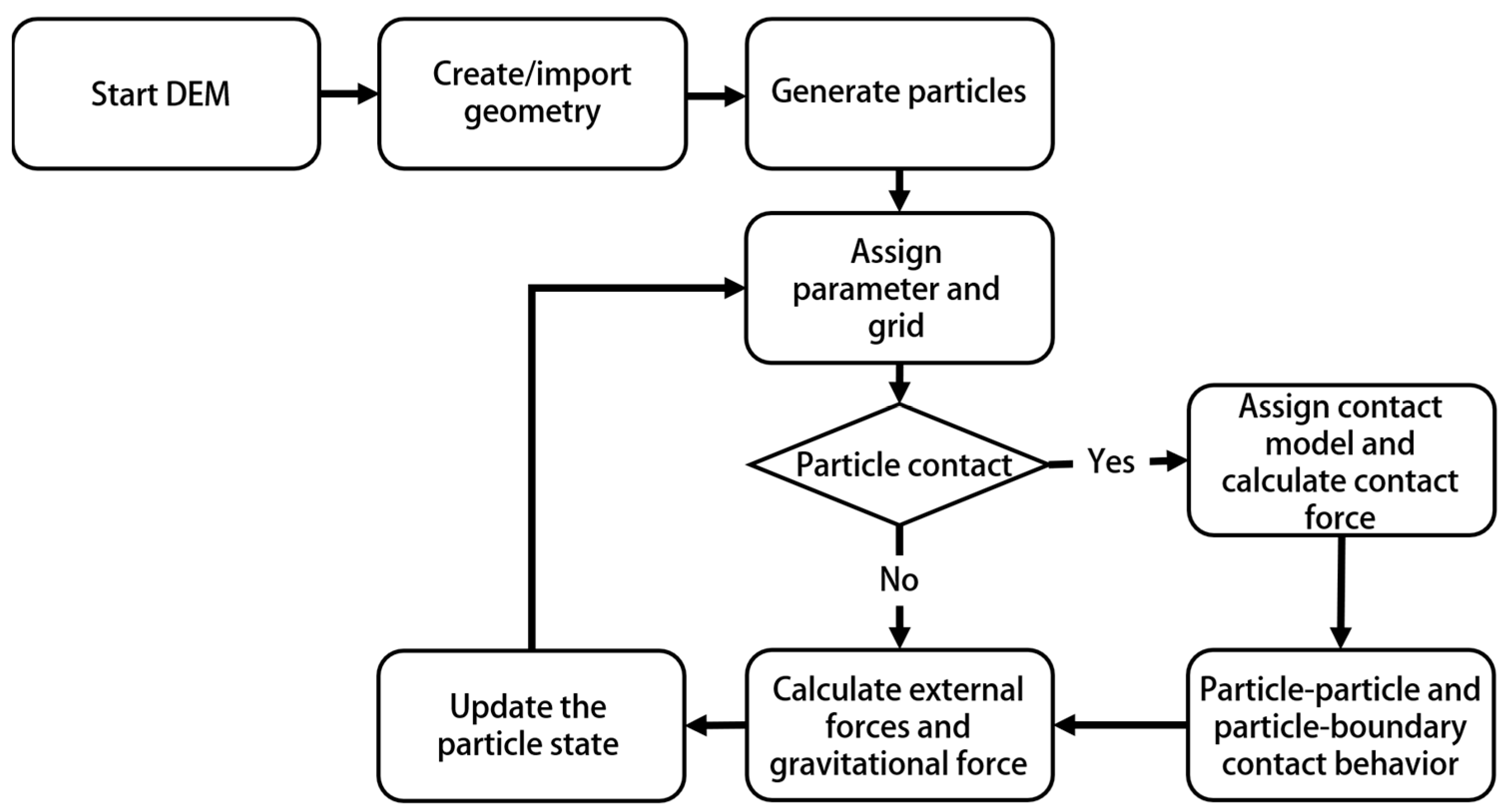
From a technological perspective, DEM can be defined as a technique that comprises finite-sized bodies having the capability of relative displacement, and therefore the contact topology and force system can be updated during the computer simulation. Modeling requires input of parameters of particles and accurate incorporation of the contact model. DEM estimates forces acting on the particles through contact mechanics and a contact detection algorithm, and thereby, acceleration, velocity, and displacement are computed using Newton’s law of motion. Different contact detection techniques are employed in algorithms to reduce the computational load. In the body-based search technique, which is a hyperlinear contact detection algorithm, each particle is considered separately for the analysis. Most DEM code follows this approach wherein the computational time increases exponentially as the number of particles in the domain increases. In contrast, with the space-based search technique, the whole domain is divided into several windows, and they are analyzed in consequence to gain computational efficiency. Assigning model parameters is a major part of modeling. Some of the particle parameters may be readily available either from the literature or direct measurements. However, in case of nonavailability, those parameters need to be obtained through calibrations. Computational time depends on the algorithm chosen for the domain, and model accuracy highly depends on the selection of proper contact model and associated parameters. A general working flow chart is shown in Figure 2.

2.2. Calibration Approaches

As discussed, the determination of the appropriate contact model and model parameters in a DEM model plays a vital role in ensuring accurate representations of the physical model. DEM parameters include particle parameters and contact parameters. The selection of particle parameters is a difficult task. The selection of input parameters required for contact models makes the task more challenging. Though there is no standard procedure to calibrate DEM parameters, two approaches are commonly followed. The first method is the direct measurement approach. Although, in most cases, microscopic parameters of DEM are not measurable, attempts have been made to quantify a material’s physical parameters directly measured on a particle. Ease of measurement depends on particle scale and size [21]. It was found that the accuracy level of the DEM model may vary even though the input parameters have been measured accurately [22,23]. This method is generally most suitable where friction among particles is the dominant force, for example, in granular particle systems. The direct measurement approach will be accurate only if the particle size and shape are modeled accurately and if an accurate representation of physical contact behavior is ensured [24]. The measurement of particle microscopic parameters is arduous, if not impossible in some cases. Therefore, the second method, calibrating model parameters by measuring and matching macroscopic parameters of bulk materials, has been a more popular method among researchers.
The latter calibration approach compares the macro response of the bulk material with the measured results through an iterative procedure [25]. First, a laboratory experiment is typically conducted to measure material properties of interest. Then, the laboratory experiment is replicated numerically with a proper code of conduct. This does not assure alignment of the measured result with the predicted one. In such cases, critical DEM parameters need to be varied until a reasonable match between predicted and measured values is achieved, following the trial-and-error approach. It was noted that a macroscopic property can be matched with different combinations of microscopic particle parameters, which suggested that another macroscopic property should be considered as a second factor to ensure the uniqueness of calibrated parameter sets [26].

2.3. Implementation

Several DEM-modeling software, either proprietary or open source, are available for implementing simulations of varieties of problems dealing with particle interface. Common commercial software includes EDEM, PFC, and Rocky DEM; open-source software includes MercuryDPM, LIGGGHTS, and YADE. They are basically developed on the same principles, executing common steps of simulation including particle contact identification, implementation of contact model, and application of laws of motion and mechanics. Major differences among software include contact detection technique, user interface, post-processing capabilities, and computation performance. For example, EDEM has a three-step graphical user interface including pre-processing, simulation, and post-processing; PFC can solve the system with a combination of spheres and polyhedra having variable contact detection algorithms; Rocky DEM offers more accelerated simulation by integrating GPU cards into the computation process; and LIGGGHTS uses command line interface for pre-processing and simulation, while post-processing needs to be performed on another platform such as PARAVIEW.

3. Fundamental Studies of DEM in Soil–Plant–Machine Interactions

3.1. Contact Models

The particle–particle and particle–boundary contact models of DEM have three main components including normal force, tangential force, as well as rolling resistance models (Figure 3). Following the displacement-driven formulation suggested by Cundall and Strack [27] for DEM simulations, different methods for calculating normal and tangential displacements can be identified. Generally, elastic, plastic, viscous, cohesive, and adhesive interactions between neighboring particles are considered. The major difference between these interactions is the role of various forms of energy including molecular energy, kinetic energy, body energy, surface energy, boundary work, and their transformation in contact behavior. In the case of elastic contact, it is considered that energy and momentum are conserved. As for the rest of the contact types, the energy is dissipated in various ways through the contact points or affected areas between particles.
Biological materials in SPMI systems have tremendous variability in terms of properties and applications. As a result, the selection of an appropriate contact model to represent material behaviors in specific applications becomes a challenge. An attempt was made to classify common contact models being studied and used in applications of SPMI systems, as shown in Figure 4. A discussion of different contact models and their common applications is narrated in the following section to guide in determining which contact model is most suited for a specific application.

3.1.1. Normal Force Model

The elastic contact model is the most common model used to calculate normal force. The elastic contact model has two types: linear and nonlinear elastic models, where the linear elastic model represents a spring, and the nonlinear normal elastic model is commonly known as the Hertzian model [27,29,30,31]. The Hertzian model has demonstrated promising results in the simulation of compression tests and in determining the modulus of elasticity of agricultural grains [28]. In this approach of elastic modeling, the energy loss through contact points of particles is not taken into consideration.
The elastic–Plastic contact model contrasts with the elastic model where the plastic component introduces a plastic deformation about the contact area, thereby simulating the energy dissipation [32]. An adaptive model of elastic-ideal plastic behavior of particles was introduced by Thornton [33] and is a more advanced and realistic extension of the Hertzian elastic model. This model can be applied to dry granular material such as crop seeds with elastic behavior in the normal direction [34]. This model is also suitable for the contact mechanics study of soft biological material under high-impact velocity [35].
The visco-elastic contact model consists of a spring and a dashpot where the spring represents linear elastic behaviors, and the dashpot reflects nonlinear viscous dissipation behaviors. This model has been validated by the results of impact experiments of seeds [36,37]. This model provides the best solutions to energy dissipation mechanisms at impact velocities below the critical value for wet rapeseeds and soft biological materials such as apples and tomatoes [38]. This model is also found to be suitable in the case of rapeseed, which has considerable hardness [34].

3.1.2. Tangential Force Model

The linear elastic-frictional model, also known as the linear spring Coulomb model, combines the linear elastic spring and friction coefficient in describing static and dynamic tangential behaviors [39]. This model can determine tangential contact force during particle sliding as well as non sliding. This model was found to be suitable for simulating the pneumatic separation of bagasse particles [40].
The Mindlin–Deresiewicz model was developed based on the Mindlin–Deresiewicz contact theory, which calculates the entire past loading history, the initial state of loading, and the instantaneous relative rates of the force change for the tangential force [41]. Vu-Quoc and Zhang [32] improved and extended the theory by elaborating the tangent force-displacement model for the elastic frictional contact of particles. The model can be applied to many special and complex cases of loading histories, and it has been used for the simulation of soybean-inclined chute interaction [42].

3.1.3. Adhesion and Cohesion Model

The Johnson–Kendall–Roberts (JKR) model, a nonlinear model, incorporates the adhesive forces in the Hertzian contact area while considering stored elastic energy and surface energy losses [43]. The adhesive inter-particle forces are mainly related to the van der Waals force or electrostatic force. However, other inter-particle forces, such as liquid bridge, a result of surface tension force and capillary pressure, may also be simulated in behavior studies of the particles having a size in the range of millimeters [44,45]. The model can effectively analyze various situations of adhesion. Anand et al. [46] simulated particle discharge from a container with the adhesion resulting from the liquid bridge in the contact model. It is suggested that the cohesive behavior of the particles needs to be accounted for in the case of biological material with a higher level of moisture content. Therefore, this model offers a good solution in the studies of moist soil–tool interaction, plant–root interaction, and grains at high moisture levels.
Cohesive materials are often modeled using the bonded particle model (BPM), which approximates the mechanical behavior of continuum material by representing it as a cemented granular material as proposed by Potyondy and Cundall [47]. The bonds of finite stiffness exist at contacts to carry forces and moments. A bond can deform and will break if the threshold of force or moment exceeds the specified strength of the bond. In recent years, this model has shown its ability to simulate biological material such as soil, leaves, stems, and stalks in the applications of tillage [48] and harvester [49].

3.2. Model Parameters

DEM modeling of SPMI systems mainly involves the study of soil interaction with biological plant materials and machine components. Specifically, soil–machine, soil–plant, and plant–machine interactions are commonly considered. Model parameters are categorized as material parameters and interaction parameters [50]. Material parameters deal with the physical and mechanical properties of a particle such as its shape, size, density, elasticity, plasticity, shear modulus, Poisson’s ratio, and yield strength. Interaction parameters deal with the static and dynamic properties of an interaction system such as adhesion, viscous damping, and coefficients of static and rolling friction [37,51].
DEM has been successfully applied to soil–machine interactions in agriculture (e.g., [52,53,54]). The major challenges of using DEM involve determining the appropriate contact model and associated parameters for agricultural soils so that the model reflects the behaviors of the biological material. Model parameters of the machine component including density, shear modulus, and Poisson’s ratio of various types of metal materials such as steels, cast irons, and alloys are relatively straightforward to measure and implement in DEM simulations. There were a few studies focused on selecting appropriate contact models for agricultural soils (e.g., [55,56,57,58]). The sensitivity of model parameters on model behaviors has been studied [59,60], providing information for determining which model parameters should be calibrated. Numerous methods were used for calibrations with the direct measurement of bulk material being the most-used approach as described above. For example, Asaf et al. [61], Ucgul et al. [57], and Tamás and Bernon [62] simulated the cone penetration test to calibrate the soil shear modulus and soil-to-soil bond stiffness. Zhang et al. [49] performed the angle of repose test to calibrate soil–soil contact parameters including the coefficient of static friction and rolling friction coefficient. Similar studies have been carried out to calibrate the contact parameters in grain–grain, soil–residue, and soil–grain interactions [50,63,64,65]. Most existing models employed the contact models implemented in DEM software. These contact models may not be the best for modeling agricultural soils. For example, Sadek and Chen [59] used an existing contact model and found that their discrete element model underestimated soil movement resulting from a blade, possibly attributable to the contact model used. Researchers are encouraged to explore some user-defined contact models. Inappropriate contact models could be one of the reasons for discrepancies between simulations and measurements reported by many other researchers. In summary, robust contact models need to be developed, and appropriate model parameters need to be determined for successful DEM applications in SPMI system simulations.

4. Applications of DEM in Soil–Plant–Machine Interaction Studies

SPMI systems can be found in all major field operations of agriculture production ranging from tillage to harvesting. Common biological plant materials considered in SPMI systems include leaves, roots, grain, fruit, residue, and whole crop plants depending on the specific field operation. Taking tillage operation as an example, a soil-engaging tool working in conservation tillage systems, where 30 to 100% of crop residue is left in the fields, forms a system of soil–residue–machine interactions. SPMI can be depicted as a system with inputs and outputs, in other words, variables and measurements [66]. The variables are mainly initial soil conditions, tool configurations, crop information, and operating conditions. The measurements may include final soil and plant conditions and machine response depending on the applications. The machine response includes forces and stresses, energy requirements, and wear. Therefore, the investigation of SPMI can be generalized as the study of the dynamic relationships between the variables and the measurements considering various relevant factors and how these variables ultimately affect soil-, plant-, and machine-related measurements. Using the tillage process as an example again, dynamic characteristics of the interactions mainly include contact forces (e.g., tool draft, vertical, and lateral forces), displacement (e.g., soil movement and residue incorporation), and size reduction (e.g., soil pulverization and residue cutting). The importance of gaining a comprehensive understanding of soil and plant dynamics involved in SPMI systems is twofold: (1) It forms the foundation of the contemporary discipline of soil dynamics; (2) It is a prerequisite for designing high-performance agricultural machinery to attain desired dynamic characteristics in consideration of real-time existence of biological plant materials.
The dependence among the variables significantly increased the complexity of the investigation into SPMI systems. The effect of working speed depending on soil conditions is a good example when studying the affecting variables of draft force in tillage. Draft force is widely known to have a quadratic relationship with a tool’s working speed [67]. However, the draft–speed relationship depends on the soil moisture content in which the polynomial curve transforms from a concave shape to a convex shape as the moisture content increases [68]. Furthermore, the dependence on moisture content responds in an opposite direction in the context of clay soil [69]. The relationship between draft force and speed has also been reported as linear, parabolic, and using exponential functions under different experimental conditions [70]. To the best of the authors’ knowledge, there is no well-established theory or robust model that could explain all these interactions. Furthermore, the heterogeneous nature of soil and plant materials and their nonlinear behaviors, combined with the large displacement and nonuniform distribution in motion, cause significant challenges in using continuum-based numerical methods. Thus, DEM is well positioned to simulate machine performance in field operations involving complex soil and plant materials.
Previous studies reported the implementation of DEM in examining soil–crop, soil–residue, or soil–seed interactions along with the interface of different implements [49,63,65,71,72,73,74,75]. For example, Zeng et al. [65] simulated the emergence dynamics of soybean seedlings through the soil and quantified cotyledon–soil dynamic characteristics including soil resistance, number of the contact points between soil particles and cotyledon, and soil kinetic energy. The soil–seed simulation of seedling emergence and growth is valuable in providing guidance and recommendations for seedbed preparation and tillage applications [76,77]. Detailed discussion and review of applying DEM in SPMI studies are provided in the following sections according to their applicable field operations.

4.1. Tillage

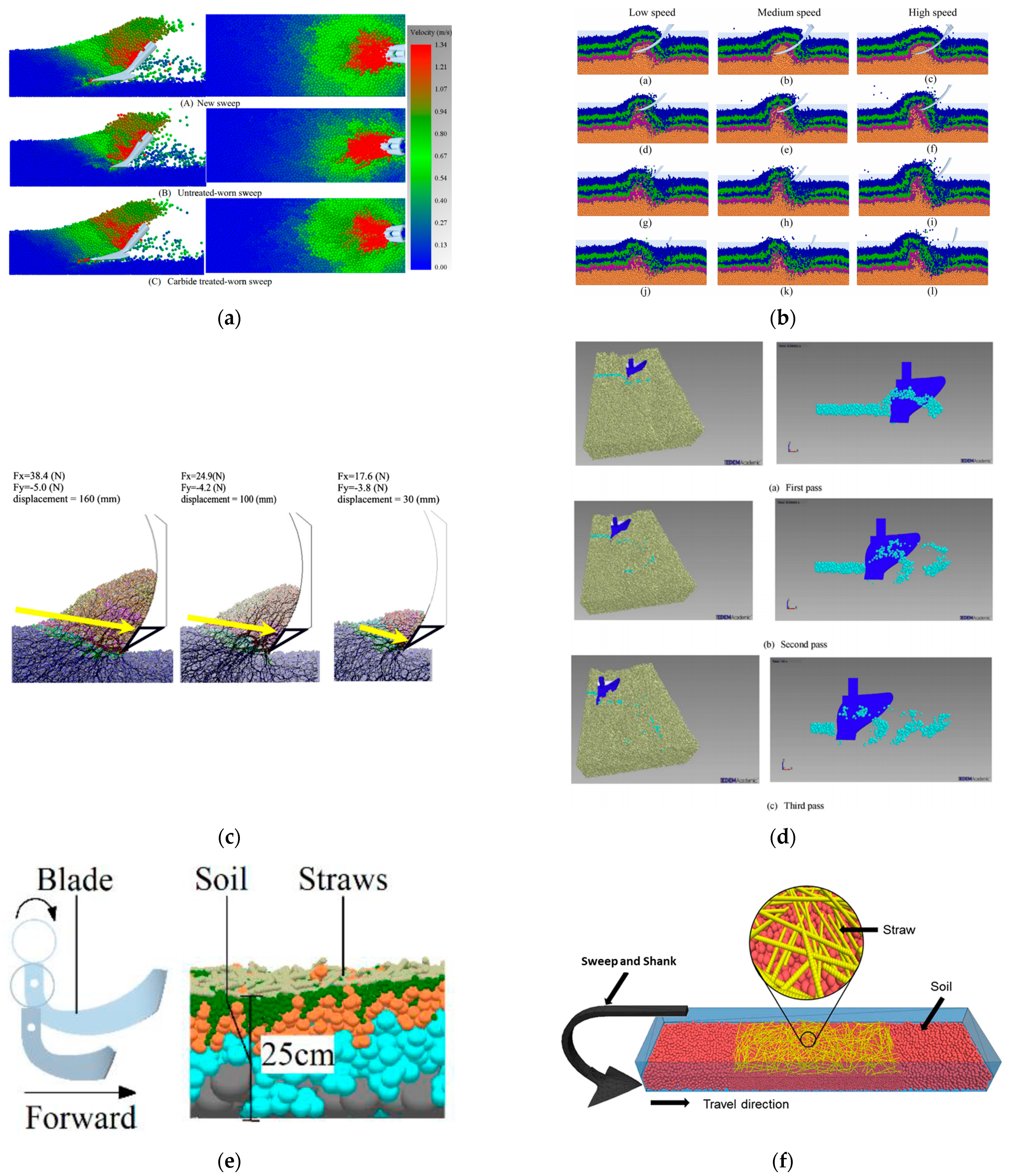
Tillage is one of the most important and energy-intensive processes in farming. The optimization of the tillage tool could improve energy efficiency and working performance. DEM has demonstrated potential applications in tillage tool development in terms of soil cutting forces and soil behavior investigation. Many studies have simulated the performance of different tillage tools at different soil and field conditions, as well as at different design and operating parameters. In certain complex situations, coupling DEM with other numerical simulation methods could improve the efficiency and accuracy of the model. For example, a problem involving structural analysis, fluid dynamics, and soil dynamics is typically solved by coupling FEM-CFD-DEM for designing more efficient and lightweight tillage implements. However, the consideration of heterogeneity and different compaction levels in the soil profile over the depth of the field was hardly included in previous studies. Researchers have also found that soil parameters such as soil porosity and particle shape are the most challenging part of parameter determination. The model parameters of soil, plant, and machine components used in SPMI studies applicable to tillage are presented in Table 1. Common tillage implements simulated include sweep (Figure 5a), subsoiler (Figure 5b), wide cutting blade (Figure 5c), moldboard plow (Figure 5d), rotary blade (Figure 5e), and the inclusion of straw (Figure 5f).
Table 1. Range of parameters used for soil–plant–machine interaction in tillage applications.
ParametersSoil a–kPlant j,k 1Machine a–k
Particle size (mm)2.5–305-
Particle density (kg m−3)1346–26800.227–0.247800–7865
Shear modulus of particle (MPa)1–60170,000–79,000
Poisson’s ratio of particle0.3–0.40.40.25–0.35
Coefficient of restitution0.01–0.60.28–0.30.01–0.5
Coefficient of friction0.36–0.770.3–0.540.31–0.7
Coefficient of rolling friction0.08–0.60.01–0.05-
Note: Superscripts indicate the source of data: a [56]; b [78]; c [79]; d [80]; e [81]; f [82]; g [48]; h [83]; i [71]; j [75]; k [84]; Subscripts indicate the materials included: 1 Straw.
Several studies have focused on soil–sweep tool interactions using DEM. Ucgul et al. [56] simulated the draft force, vertical force, and furrow profile of a sweep tool. They found that the simulation with a top layer consisting of smaller particles provided a more accurate representation of soil flow and furrow profile with a doubled computation time. Tamas et al. [87] explored the working performance of a sweep in terms of soil loosening, draft force, and energy requirement. The results showed a very good match between the measured and calculated draft force. The highest level of loosening was obtained for the sweep at a rake angle of 45°. The tillage draft and vertical forces of the sweep were measured by Ucgul et al. [56]. The results showed that the hysteretic spring contact model, which considered both the adhesion and cohesion forces, improved the prediction accuracy of the draft and vertical force. Tekeste et al. [82] investigated the effects of different sweep design parameters on geometric wear dimensional loss, which could affect soil–tool dynamics including draft force, vertical force, and soil upward failure distance. The Hertz–Mindlin with parallel bond model was used in the study. The results showed that the carbide treatment of the sweep was effective in reducing wear, improving longevity, and maintaining soil tilth quality performance of the tool. The soil–tool interaction in the sweep cultivation process was studied by Milkevych et al. [88], who found that the maximum longitudinal displacement of soil occurred at the tip of the sweep and decreased rapidly to zero along the transverse direction.
Identification of the soil behavior as it is subjected to subsoiling and the mechanism of subsoiler–tool interaction are vital to study using DEM simulation. Hang et al. [89] investigated the effect of tine spacing on soil disturbance in the search for optimal tine spacing. Hang et al. [78] explored the micromovement and the macro-disturbance behaviors of the soil under the impact of subsoilers. The results showed that the forces exerted on soil particles increased as the subsoiler was operated in deeper soil layers, thereby resulting in a higher level of disturbance. Zhang et al. [85] used Hertz–Mindlin with the JKR contact model and Hertz–Mindlin with the bonding model to represent tillage layer and plow pan layer, respectively.
Some investigators have also used DEM simulation to study the interaction between soil and a wide cutting blade. The energy ratio, strain energy, body energy, deformation, and elasticity of grains were explored by Asaf et al. [61]. The results showed that the magnitude of friction energy was comparable to the magnitude of total energy. Kotrocz et al. [90] observed that the penetration resistance increased as the cross-sectional area of the blade decreased. Obermayr et al. [91] simulated the draft force of a straight blade moving at a constant speed through a cohesionless granular material. The results showed that the draft force increased as the blade width and cutting depth increased.
Recently, some researchers used DEM to simulate the moldboard plow improvement process. Ucgul et al. [79] carried out soil bin testing to measure the forces and soil movement and developed a DEM model based on a linear cohesion integrated hysteretic spring contact model accordingly. The results showed that the DEM model could reproduce the soil bin test results. In another study, Ucgul et al. [80] carried out full-scale modeling of a moldboard plow and compared the soil movement and tillage forces with the measured data from a field test.
The performance of rotary tillage implements in covering rice straw under the soil surface was analyzed by Zhang et al. [75]. Four different soil particle radii viz. 5 mm, 10 mm, 15 mm, and 30 mm along with straw composed of a 5 mm radius were incorporated into the model using the Hertz–Mindlin with bonding contact model. They proposed the optimized structural parameters for the rotary blade based on the simulation results. The relative errors between the simulation and field test for different parameters were less than 10%.
The soil–oat-straw-sweep interaction study was carried out by Zeng and Chen [83], in which the virtual field consisted of a top straw layer and a soil layer underneath with parallel bond contact model. Model parameters of ball stiffness and clump stiffness were calibrated, and several parameters including soil and straw moving area, residue cover, and kinetic energy were monitored. The simulation results were compared with the lab test results, which showed good agreement with an average relative error of 7.3%.
In applications of DEM modeling in tillage, the existing work focuses more on shank-type soil-engaging tools, such as sweeps and moldboard plows, than on passive rotary tools, such as disc plows and rotary vertical tillage tools. The main challenge is that it is impossible to simulate the ground-driven feature of rotary tools in real life in DEM modeling. The soil dynamic attributes mostly dealt with are more often soil cutting forces than soil disturbance characteristics, which are relatively more difficult to monitor using DEM. In addition, considering crop residue as a part of a soil–tool/machine system requires further study, as conservation tillage (with residue cover) is gaining more popularity.

4.2. Seeding and Planting

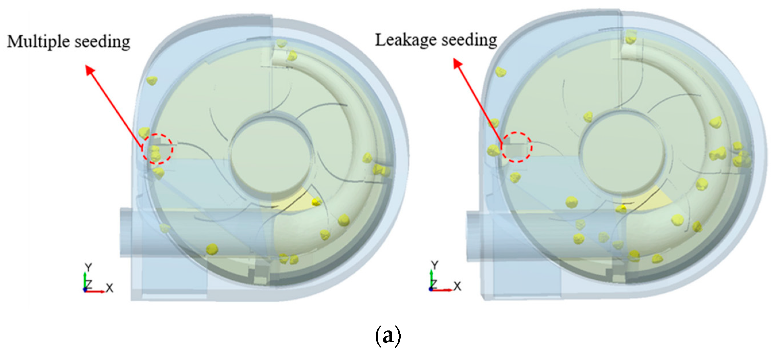
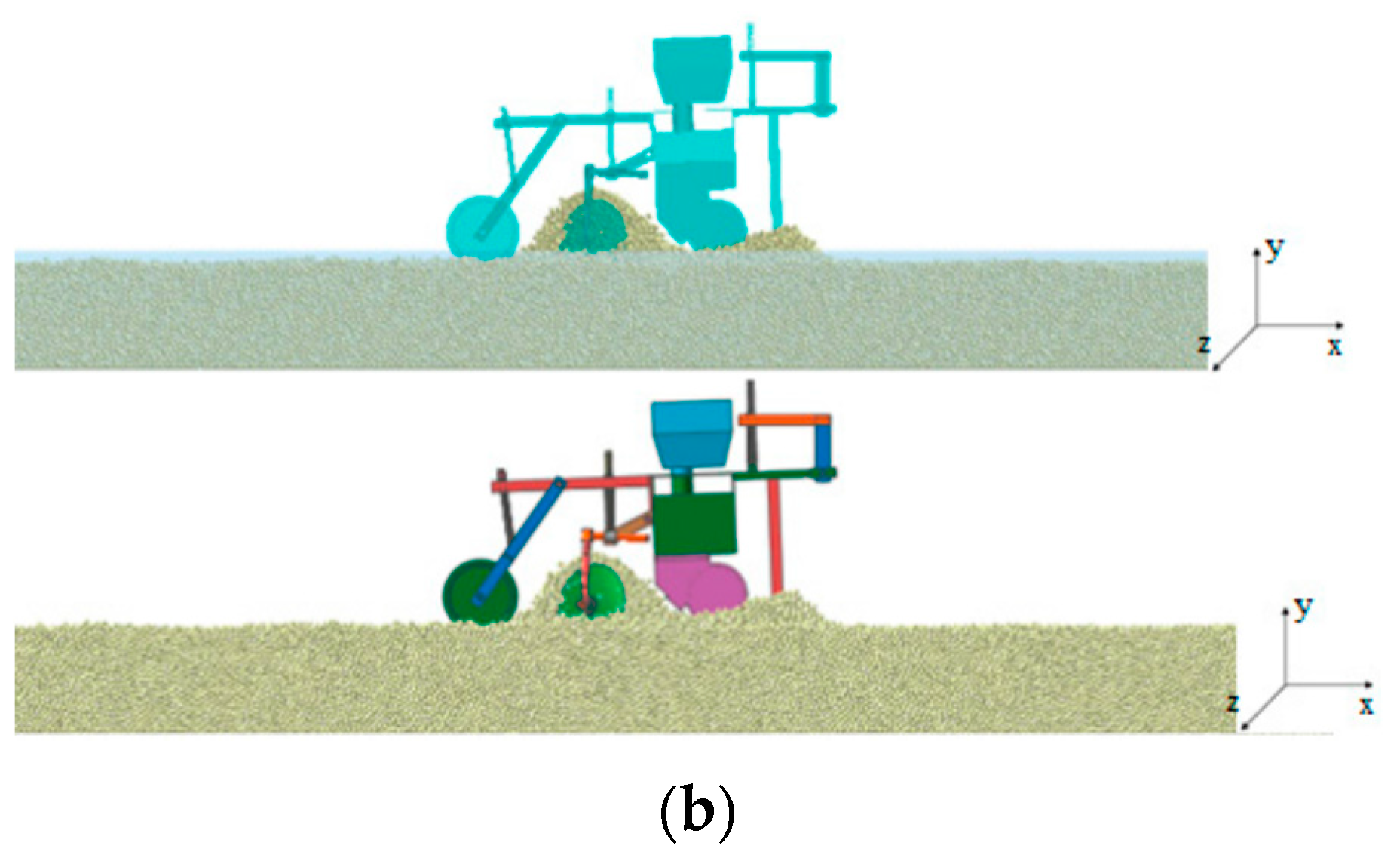
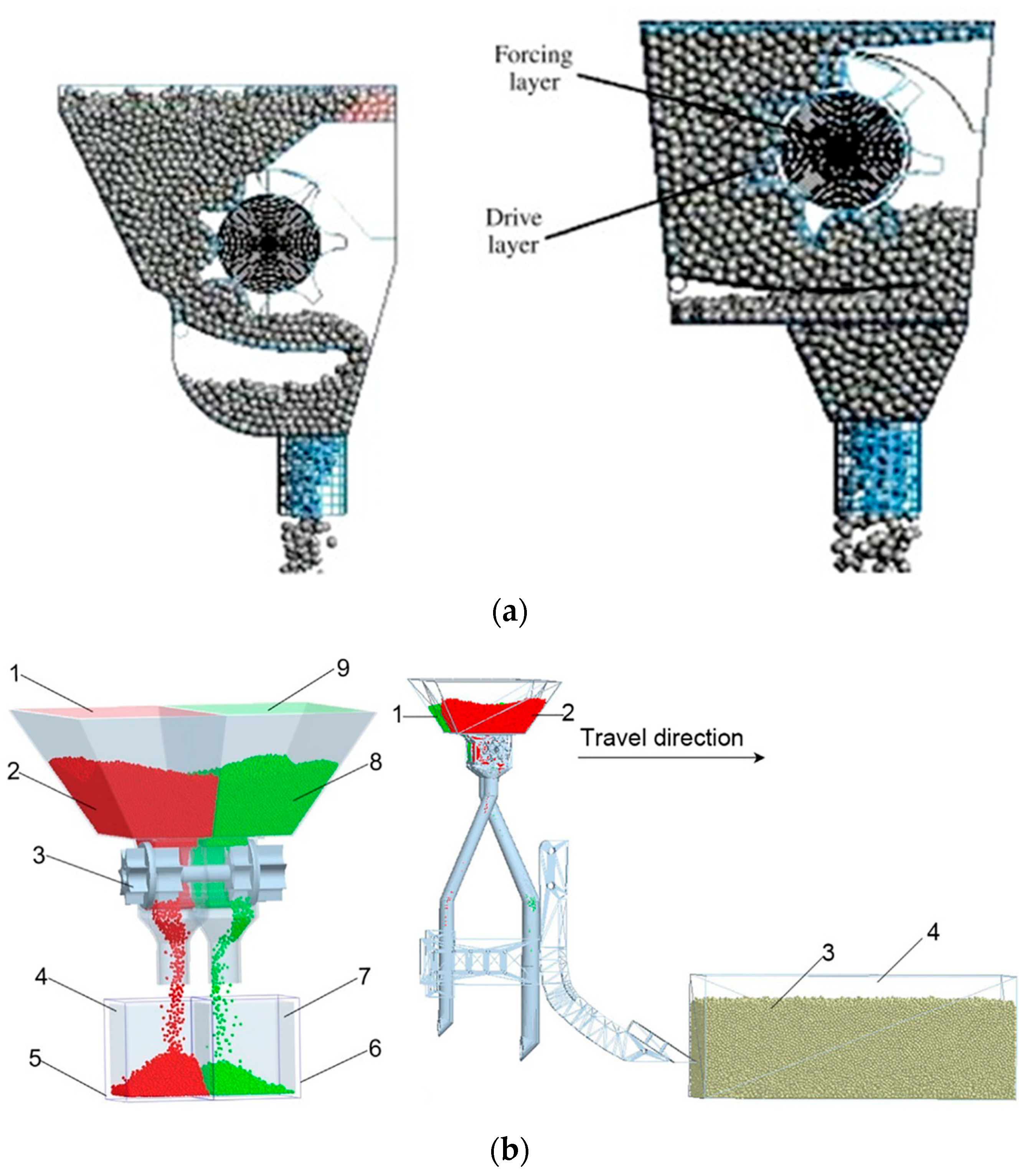
Soil and residue clogging into the delivery end of the soil-engaging tool or implement is a major concern in the operation of seeding and planting machines. The clogging would be exacerbated by the varying levels of residue cover and soil moisture that the seeding and planting implement is usually dealing with [92]. It is also challenging to prevent blockage and nonuniformity of the seed-metering device, which has significant implications for yield and productivity. DEM could be a promising modeling tool to simulate the performance of the seeding and planting machines working in various types of soil and residue field conditions [93]. Many studies have focused on seed or seedling dynamics inside the metering device, such as seed–hopper interaction (e.g., Figure 6a [94]). However, seed–soil interaction is rarely studied; one such example is from Yan et al. [95] as shown in Figure 6b. Soil clogging at the seed delivery end is quite frequent and could lead to serious production losses. In addition, it has been observed during field operations that seeds are often dislocated or misaligned at the time of delivery into the furrow. DEM could be used to investigate the possibility of soil clogging, seed missing, and seed dislocation during the operation. DEM studies on SPMI systems could help to optimize operational and design parameters to minimize the above losses. Furthermore, to the best of the authors’ knowledge, the study of soil–seedling–machine interaction in transplanters has not yet been studied using DEM. In conclusion, an attempt has been made to elaborate the applications of DEM for modeling different configurations of seed-metering devices and planters at different soil conditions [84,96,97,98,99]. In addition to this, the model parameters used for SPMI systems in the seeding and planting applications are presented in Table 2.
Li et al. [97] reported a DEM simulation study of the wheat seed movement in the filling-in wheel type variable seed-metering device. The seed-filling performance with different hole structures, filling postures, and vibration conditions were investigated. Wang et al. [100] reported the study of a single-bud billet seed-metering device for sugarcane planting. Each billet of cylindrical shape was assembled using three spherical particles with diameters ranging from 25 to 30 mm, and the Hertz–Mindlin (no-slip) contact model was selected for the particle-to-particle and particle-to-boundary contact. Their DEM model could predict the experimental results with a relative error of 6.67%.
Yan et al. [95] simulated the soybean planting process, which involves furrow opening, seed dropping, covering, and compaction of the soil. A detailed analysis of the seed position, furrow opening, and seed spacing at varying working speeds has been reported. However, the authors did not report the contact model used in their simulation.

4.3. Fertilizing

A fertilizer applicator is used to apply the desired amount of fertilizer at a predetermined rate to crops and fields. Generally speaking, solid and liquid fertilizers, either organic or mineral, are applied to the soil surface or into the soil at varying depths. In the case of surface application, DEM simulation could be focused on the study of metering device and carrier tube (Figure 7a). For example, fertilizer spreading pattern, mass flow rate, and motion and agglomeration of fertilizer particles are suitable candidates for model measurements. However, in the case of deep application, the interaction between the fertilizer delivery tool and the surrounding soil should also be considered (Figure 7b). The model parameters of soil, fertilizer, and machine components used in SPMI studies related to fertilizer application are presented in Table 3.
Table 3. Range of parameters used for soil–fertilizer–machine interaction.
ParametersSoil a,dFertilizer a–d 1–4Machine a,c,d
Particle size (mm)6–121.27–6-
Particle density (kg m−3)1357–260062·0–16301240–8000
Shear modulus of particle (MPa)1–500.25–35.61300–72,700
Poisson’s ratio of particle0.3–0.40.25–280.3
Coefficient of restitution0.2–0.40.11–0.60.36–0.6
Coefficient of friction0.4–0.660.3–0.650.32–0.7
Coefficient of rolling friction0.18–0.30.01–0.150.04–0.18
Note: Superscripts indicate the source of data: a [101]; b [102]; c [103]; d [104]; Subscripts indicate the materials included: 1 Ammonium phosphate; 2 Compound fertilizer; 3 Urea fertilizer; 4 Organic fertilizer.
Bangura et al. [102] studied fertilizer discharge characteristics including mass flow rate, discharge uniformity, and falling velocity of two grooved-wheel metering devices using DEM. Experimental trials were performed and compared with the simulation results, which found that the relative errors were less than 10% for all the examined characteristics. Lv et al. [105] simulated fertilizer spreaders with different structures and sizes using DEM. A linear visco-elastic model was used to calculate the contact force between fertilizer particles and spreaders.
Deep fertilization has been an increasingly popular choice for crop nutrient management due to its efficient utilization by plants and volatility reduction of nutrients. Several studies have simulated deep application of different types of fertilizers including chemical-granular, organic-granular, and chemical-liquid. The dual-band fertilizer application has been experimentally studied and numerically simulated by Ding et al. [101]. Different meter roller lengths, working speeds, and delivery tube spacings were considered in the simulation. Yuan et al. [104] developed a screw augur with a paddle for mixing organic fertilizer with soil during transportation, and DEM simulation was carried out using two distinct contact models including the Hertz–Mindlin with JKR model for organic fertilizer and the Hertz–Mindlin (no-slip) model for soil. The maximum relative error between the simulation and experimental results was 8.95%.

4.4. Harvesting

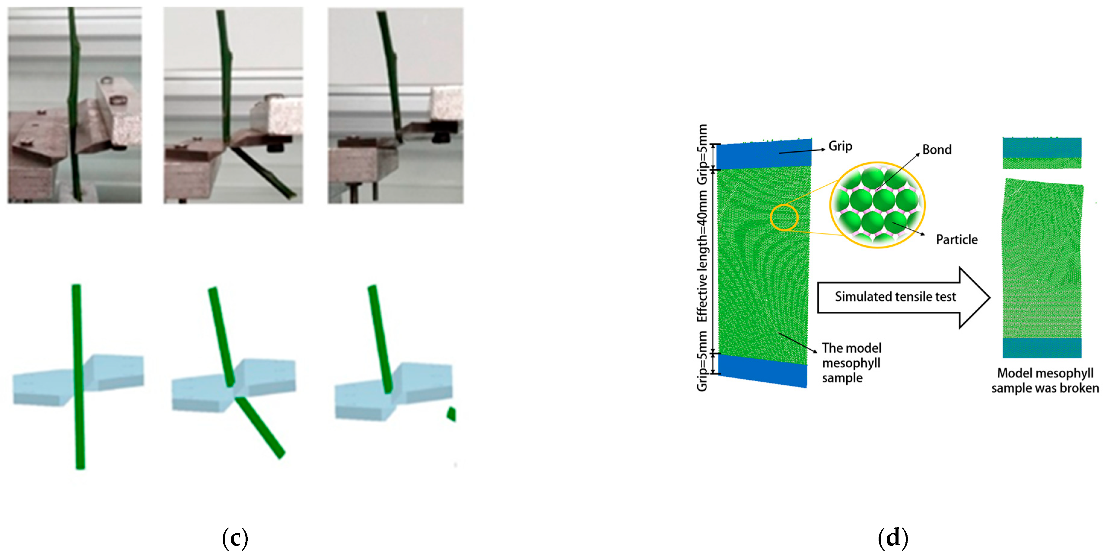
Harvesting is a major and vital step in crop production as poor harvesting practices and handling techniques of the product would lead to huge losses in the field. Furthermore, poor design and inefficient mechanisms of harvesters would increase the drudgery and decrease the productivity of workers. Therefore, design improvement of critical components of harvesters including cutting, collecting, separating, and cleaning systems plays an important role in ensuring a highly efficient and effective harvesting operation. FEM has been successfully used for the structural design of harvesters to optimize the mechanical components for better strength and durability performance. However, crop–machine interaction needs to be examined for proper material handling in the harvester to increase operational efficiency. It is thus suggested that the dynamic behavior of crop materials and their interaction with harvesting machine components can be simulated using DEM [106,107,108,109,110,111,112]. Several researchers have reported significant results of DEM modeling of grain crops (Figure 8a), root crops (Figure 8b), and other plant materials including stalks (Figure 8c) and leaves (Figure 8d) interacting with machines. The DEM parameters used in the literature for soil–plant–machine interaction in harvesting applications are presented in Table 4.
Table 4. Range of parameters used for soil–plant–machine interaction in harvesting applications.
ParametersSoil dPlant b,d,e 1–5Machine b,d
Particle size (mm)-3-
Particle density (kg m−3)2600380–15407800–7850
Shear modulus of particle (MPa)-42070,000–79,000
Poisson’s ratio of particle0.50.25–0.40.3
Coefficient of restitution0.1230.21–0.50.1487–0.37
Coefficient of friction0.38530.5–0.75870.5–0.6135
Coefficient of rolling friction0.2670.01–0.61870.25–0.3262
Note: Superscripts indicate the source of data: b [110]; d [113]; e [114]; Subscripts indicate the materials included 1 Rice straw; 2 Rice plant; 3 Citrus fruit stalks; 4 Taro plant; 5 Tobacco leaf.
Grain crops are typically harvested with combine harvesters following several sequential operations including stem cutting, seed threshing, separation of grain, cleaning, and conveying [108,109]. DEM simulation has been used to study performance parameters of the thresher and baler, such as threshing rate, separation rate, and feeding dynamics. However, other important parameters of the harvesting process such as straw plugging rate and grain damage rate are rarely studied. Furthermore, the moisture content in straw should be considered for accurate simulation. Wang et al. [110] simulated the threshing process of rice including rice ear and stem. Rice leaves and secondary branches of the rice ear were neglected. A rice stem is a hollow rod consisting of 93 particles bonded in a line. A rachis is formed by bonding 62 particles in a line. The rice grains were attached to the rice spikes through connection particles, not virtual bonds, to ensure that the bonds between the rice stem particles are not destroyed while rice grains are being knocked down from the spikes. Mao et al. [107] reported the modeling of a straw–grain separation process using the bonded particle straw model (BSM) with elastic hollow cylindrical bonds. The model was experimentally calibrated for compression, bending, stretching, and separation. It was concluded that the grain particle shape and the moment of inertia of grain particles can be accurately simulated with BSM.
Root crops such as potato, sweet potato, taro, ginger, onion, and carrot are widely planted in the world. The harvesting of these crops has been a major concern due to its high energy consumption and labor demand, as well as the poor working performance of conventional harvesting machines. Typically, digging blades and conveyor systems were used to collect and transport root crops to separation systems. Soil shear property and compaction need to be studied in designing the digging blade and conveying mechanism. In the case of the clamping and pulling mechanism, the microscopic properties of the granular soil, clamping resistance, and soil resistance need to be taken into consideration in the design process. Liu et al. [113] simulated the tiller taro harvesting process using Hertz–Mindlin with a flexible bonding contact model. The parameters were calibrated using a single-factor experiment with the Plackett–Burman method. Li et al. [115] designed and simulated a belt-rod type self-propelled potato harvester. The soil separation mechanism and its soil removal effectiveness were investigated by coupling DEM with the multi body dynamics (MBD) method. The DEM model was developed using the Hertz–Mindlin contact model with bonding. The model was validated with field experiments, and the relative error between results was 3.81%.
As discussed earlier, the harvesting mechanism design was usually based on the physical properties of the crop harvested. Therefore, measuring and simulating the physical and mechanical properties of various parts of crop plant are important for the efficient design of the harvester. Wang et al. [111] developed a DEM model to simulate the bending and shearing of citrus fruit stalks having a 3 mm diameter. The simulated mechanical properties were in good agreement with the experimental results with relative errors of less than 2%. In a similar type of study, Sadrmanesh and Chen [116] developed a model to simulate the tensile behavior of the plant fiber. The model was constructed of bonded spherical particles. They suggested that the fiber should be modeled with an adequate number of particles and bonds to have a good particle assembly, which can represent the solid nature of the plant fiber. In another such study, the tensile behavior of tobacco leaves was simulated by Tian et al. [114], where the tensile fracture was found to be random in the simulation, similar to real-world observations.

5. Opportunities and Challenges

5.1. Emerging Fields

DEM modeling has been used to study the mechanics of granular material interactions in agriculture productions. The presence of fluids such as air and water in such granular systems cannot be avoided. Thus, multiphase system simulation coupling particle mechanics and fluid dynamics is necessary to obtain accurate and realistic modeling results. The potential of this method also offers interdisciplinary research opportunities involving soil science, irrigation engineering, soil and water conservation engineering, farm machinery, fluid power engineering, food process engineering, and much more. Among many numerical methods, FEM, CFD, and MBD are the most widely used methods for kinematics, dynamic, and thermal studies of particle–fluid systems. In recent years, many researchers have successfully coupled these methods with DEM and solved complex engineering problems in agriculture [117,118,119,120,121]. In a DEM–CFD coupled model, the particle flow characteristics are assigned in the DEM model, and associating fluid flow field is solved in CFD. Thus, kinematic and physical properties assigned to each particle of the fluid are linked to the corresponding grid in DEM. DEM has limitations while simulating motion dynamics of tools such as a rotary blade, conveyor belt, etc. Meanwhile, MBD offers an accurate solution to simulate the tool dynamics in soil–tool interaction. Thus, a DEM–MBD coupled model offers solutions to simulate complex tool motion and predict soil reaction forces on the tool.
In recent years, virtual rapid prototyping has gained interest in modern manufacturing industries. It involves the construction and testing of a realistic and interactive design, the so-called e-design, which enables simulations of the product performance through 3D visual effects [122]. This e-design may include the coupling of CAD, CFD, FEM, and DEM. For example, in 3D printing rapid prototyping of fiber-reinforced polymer composites, CAD was used to define the shape and physical characteristics of the product; FEM was used to study the polymer melt flow and thermal expansion of the material during the operation; CFD was utilized to simulate the flow characteristics, thermal stress, and heat transfer mechanism of the product; and DEM was used to simulate the fiber–fiber and fiber–nozzle interactions, which together helped to predict nozzle clogging, fiber breakage, and fiber misalignment during the operation [123,124,125]. Similar coupled virtual rapid prototyping techniques could be used in the study of SPMI dynamics and assist in the development of innovative and efficient agricultural implements.

5.2. Future Challenges

It is noted that DEM is a popular and widely accepted tool for simulating the mechanical behaviors of granular materials at the microscopic level. However, in many applications such as the modeling of soil, a huge number of particles need to be generated, and their interaction matrices need to be solved in the DEM model to produce a highly accurate and real-time behavior of the particle system. This leads to the complex computation of the model and incurs a significantly high cost of computation, which in turn limits the application of DEM in complex engineering problems. Attempts have been made to improve the computational efficiency of DEM, for example, by using optimized modeling algorithms [126], parallel computing with multicore processors [127], and multiscale modeling approaches [128]. The multiscale approach could provide more realistic and accurate solutions in an efficient way by using coupling continuum (e.g., FEM and CFD) and discontinuum (DEM) numerical simulation methods to take advantage of different methods in handling different scales of physical phenomena, i.e., discontinuum-based larger scale phenomena and continuum-based local scale phenomena. However, multiscale modeling typically lacks the mechanism of uncertainty quantification. Microstructural unpredictability, inherent stochasticity, lack of prediction of microstructural phenomena, and loss of information through discrete-to-continuum upscaling have been identified as the main sources of uncertainty in discrete-continuum multiscale modeling [129]. Thus, the development of uncertainty quantification methods is necessary to investigate the sensitivity of model responses to variability in the microstructure at different levels. In addition, it is necessary to evaluate the uncertainty propagation through the multiscale model chains [130,131].
It is observed from the literature review that most of the previous studies either directly adapted published values or relied on calibration in determining model parameters. In some instances, the model parameters have been selected from the literature based merely on whether the experimental conditions fit into their work [71,74,75,97,110]. As a result, simulation accuracy varied between the referred and proposed studies [96,101]. As for calibration, different calibration methods and experimental procedures are commonly being followed for the same material parameter, which clearly indicates the lack of a universal calibration procedure for specific material parameters. Some researchers also argued in their review that DEM modeling lacks a widely accepted robust calibration procedure. It is, thus, an urgent necessity to define the universal calibration method for the determination of DEM model parameters.

6. Conclusions

This paper reviews DEM modeling and simulation of agricultural field operations mainly focusing on the interactions at the interface of soil, plant, and machine. The fundamentals, methodology, and assumptions of DEM modeling as well as its applications in different SPMI systems including tillage, seeding and planting, fertilizing, and harvesting are presented. Various calibration strategies in DEM modeling are also summarized in this paper. It also discusses the selection and determination of different contact models and their parameters. It was observed that DEM modeling can be effectively used to study SPMI systems including soil–machine, soil–plant, and plant–machine interactions. Soil–machine interaction studies have helped to optimize the design parameters of the machine. Tillage tools including sweep, subsoiler, moldboard plow, and blades were modeled and simulated using DEM. The effects of operational parameters and tool design parameters on dependent parameters such as draft force, vertical force, soil disturbance, and energy consumption have been well documented. The plant–machine interaction simulations can assist in visualizing real-time operation and behavior of the plant materials to optimize the process parameters of the machines. Taking harvesting application as an example, previous studies revealed the effects of harvesting mechanisms on material handling, cutting forces, effectiveness, and efficiency of the harvesters. In the fields of fertilizing and seeding application, the particle flow dynamics of fertilizers and seeds through machine components until their delivery and the interaction of these particles with the soil were reported in the literature. The soil–plant interaction, commonly found in tillage and seeding applications and in the process of plant germination and emergence, was also reported in the literature. In conclusion, besides providing insight into the micro- and macro-behavior of soil, machine, plants, and their combinations, DEM simulation of SPMI systems assists the design engineer in enhancing efficiency and effectiveness in performing agricultural field operations.

Author Contributions

Conceptualization, A.W. and Z.Z.; methodology, Z.Z.; software, Y.T.; validation, Y.T. and Z.Z.; formal analysis, Y.T.; investigation, A.W.; resources, A.W.; data curation, Y.T.; writing—original draft preparation, A.W.; writing—review and editing, Y.C.; visualization, Y.T.; supervision, Z.Z.; project administration, Z.Z.; funding acquisition, Z.Z. All authors have read and agreed to the published version of the manuscript.

Funding

This research was funded by the National Institute of Food and Agriculture, USDA, grant number 2018-70001-27840.

Data Availability Statement

The data presented in this study are available on request from the corresponding author. The data are not publicly available due to privacy restrictions.

Acknowledgments

First, the authors acknowledge the Centre for Advanced Agricultural Science and Technology (CAAST) for Climate Smart Agriculture and Water Management (CSAWM), which is a World-Bank-assisted National Agricultural Higher Education Project (NAHEP) of the Indian Council of Agricultural Research (ICAR), New Delhi at MPKV, Rahuri, for providing financial support to undertake the short-term research at UWRF, WI, USA. The authors acknowledge Kyle Leis at the University of Wisconsin-River Falls for their assistance with editing and proofreading. The authors thank the editor and anonymous reviewers for providing helpful suggestions for improving the quality of this manuscript.

Conflicts of Interest

The authors declare no conflict of interest.

References

  1. Ani, O.A.; Uzoejinwa, B.B.; Ezeama, A.O.; Onwualu, A.P.; Ugwu, S.N.; Ohagwu, C.J. Overview of soil-machine interaction studies in soil bins. Soil Tillage Res. 2018, 175, 13–27. [Google Scholar] [CrossRef]
  2. Liu, J.; Chen, Y.; Lobb, D.A.; Kushwaha, R.L. Soil-straw-tillage tool interaction: Field and soil bin study. Can. Biosyst. Eng. 2007, 49, 2.1–2.6. [Google Scholar]
  3. Liu, J.; Chen, Y.; Kushwaha, R.L. Effect of tillage speed and straw length on soil and straw movement by a sweep. Soil Tillage Res. 2010, 109, 9–17. [Google Scholar] [CrossRef]
  4. Liu, J.; Lobb, D.A.; Chen, Y.; Kushwaha, R.L. Steady-state models for the movement of soil and straw during tillage with a single sweep. Trans. ASABE 2008, 51, 781–789. [Google Scholar] [CrossRef]
  5. Hettiaratchi, D.R.P.; Reece, A.R. Symmetrical three-dimensional soil failure. J. Terramech. 1967, 4, 45–67. [Google Scholar] [CrossRef]
  6. McKyes, E.; Ali, O.S. The cutting of soil by narrow blades. J. Terramech. 1977, 14, 43–58. [Google Scholar] [CrossRef]
  7. Godwin, R.J.; Spoor, G. Soil failure with narrow tines. J. Agric. Eng. Res. 1977, 22, 213–228. [Google Scholar] [CrossRef]
  8. Robert, D.W.; Harold, J.L. Performance of plane soil cutting blades in clay. Trans. ASAE 1972, 15, 211–0216. [Google Scholar]
  9. Kushwaha, R.L.; Zhang, Z.X. Evaluation of factors and current approaches related to computerized design of tillage tools: A review. J. Terramech. 1998, 35, 69–86. [Google Scholar] [CrossRef]
  10. Fielke, J.M. Finite Element Modelling of the interaction of the cutting edge of tillage implements with soil. J. Agric. Eng. Res. 1999, 74, 91–101. [Google Scholar] [CrossRef]
  11. Mouazen, A.M.; Ramon, H. A numerical–statistical hybrid modelling scheme for evaluation of draught requirements of a subsoiler cutting a sandy loam soil, as affected by moisture content, bulk density and depth. Soil Tillage Res. 2002, 63, 155–165. [Google Scholar] [CrossRef]
  12. Jiang, X.; Tong, J.; Ma, Y.; Sun, J. Development and verification of a mathematical model for the specific resistance of a curved subsoiler. Biosyst. Eng. 2020, 190, 107–119. [Google Scholar] [CrossRef]
  13. Gebregziabher, S.; Mouazen, A.M.; Van Brussel, H.; Ramon, H.; Meresa, F.; Verplancke, H.; Nyssen, J.; Behailu, M.; Deckers, J.; De Baerdemaeker, J. Design of the Ethiopian ard plough using structural analysis validated with finite element analysis. Biosyst. Eng. 2007, 97, 27–39. [Google Scholar] [CrossRef]
  14. Topakci, M.; Celik, H.K.; Canakci, M.; Rennie, A.; Akinci, I.; Karayel, D. Deep tillage tool optimization by means of finite element method: Case study for a subsoiler tine. J. Food Agric. Environ. 2010, 8, 531–536. [Google Scholar]
  15. Tagar, A.A.; Ji, C.; Adamowski, J.; Malard, J.; Qi, C.; Ding, Q.; Abbasi, N.A. Finite element simulation of soil failure patterns under soil bin and field testing conditions. Soil Tillage Res. 2015, 145, 157–170. [Google Scholar] [CrossRef]
  16. Zhu, L.; Ge, J.; Cheng, X.; Peng, S.; Qi, Y.; Zhang, S.; Zhu, D. Modeling of share/soil interaction of a horizontally reversible plow using computational fluid dynamics. J. Terramech. 2017, 72, 1–8. [Google Scholar] [CrossRef]
  17. Karmakar, S.; Kushwaha, R.L. Dynamic modeling of soil–tool interaction: An overview from a fluid flow perspective. J. Terramech. 2006, 43, 411–425. [Google Scholar] [CrossRef]
  18. Li, M.; Xu, S.; Yang, Y.; Guo, L.; Tong, J. A 3D simulation model of corn stubble cutting using finite element method. Soil Tillage Res. 2017, 166, 43–51. [Google Scholar] [CrossRef]
  19. Cundall, P.A. A computer model for simulating progressive, large-scale movement in blocky rock system. Proc. Int. Symp. Rock Mech. 1971, 8, 129–136. [Google Scholar]
  20. Owen, D.; Feng, Y.; de Souza Neto, E.; Cottrell, M.; Wang, F.; Andrade Pires, F.; Yu, J. The modelling of multi-fracturing solids and particulate media. Int. J. Numer. Methods Eng. 2004, 60, 317–339. [Google Scholar] [CrossRef]
  21. Marigo, M.; Stitt, E.H. Discrete element method (DEM) for industrial applications: Comments on calibration and validation for the modelling of cylindrical pellets. KONA Powder Part. J. 2015, 32, 236–252. [Google Scholar] [CrossRef]
  22. Quist, J.; Evertsson, M. Framework for DEM model calibration and validation. In Proceedings of the 14th European Symposium on Comminution and Classification, Gothenburg, Sweden, 7–11 September 2015. [Google Scholar]
  23. Simons, T.A.H.; Weiler, R.; Strege, S.; Bensmann, S.; Schilling, M.; Kwade, A. A Ring Shear Tester as Calibration Experiment for DEM Simulations in Agitated Mixers—A Sensitivity Study. Procedia Eng. 2015, 102, 741–748. [Google Scholar] [CrossRef]
  24. Barrios, G.K.P.; de Carvalho, R.M.; Kwade, A.; Tavares, L.M. Contact parameter estimation for DEM simulation of iron ore pellet handling. Powder Technol. 2013, 248, 84–93. [Google Scholar] [CrossRef]
  25. Coetzee, C.J. Review: Calibration of the discrete element method. Powder Technol. 2017, 310, 104–142. [Google Scholar] [CrossRef]
  26. Derakhshani, S.M.; Schott, D.L.; Lodewijks, G. Micro–macro properties of quartz sand: Experimental investigation and DEM simulation. Powder Technol. 2015, 269, 127–138. [Google Scholar] [CrossRef]
  27. Cundall, P.A.; Strack, O.D. A discrete numerical model for granular assemblies. Geotechnique 1979, 29, 47–65. [Google Scholar] [CrossRef]
  28. Horabik, J.; Molenda, M. Parameters and contact models for DEM simulations of agricultural granular materials: A review. Biosyst. Eng. 2016, 147, 206–225. [Google Scholar] [CrossRef]
  29. Walton, I.O.; Braun, R. Stress calculations for assemblies of inelastic speres in uniform shear. Acta Mech. 1986, 63, 73–86. [Google Scholar] [CrossRef]
  30. Walton, O.R.; Braun, R.L. Viscosity, granular-temperature, and stress calculations for shearing assemblies of inelastic, frictional disks. J. Rheol. 1986, 30, 949–980. [Google Scholar] [CrossRef]
  31. Walton, O.R. Numerical simulation of inclined chute flows of monodisperse, inelastic, frictional spheres. Mech. Mater. 1993, 16, 239–247. [Google Scholar] [CrossRef]
  32. Vu-Quoc, L.; Zhang, X. An accurate and efficient tangential force–displacement model for elastic frictional contact in particle-flow simulations. Mech. Mater. 1999, 31, 235–269. [Google Scholar] [CrossRef]
  33. Thornton, C.; Ning, Z. A theoretical model for the stick/bounce behaviour of adhesive, elastic-plastic spheres. Powder Technol. 1998, 99, 154–162. [Google Scholar] [CrossRef]
  34. Parafiniuk, P.; Molenda, M.; Horabik, J. Discharge of rapeseeds from a model silo: Physical testing and discrete element method simulations. Comput. Electron. Agric. 2013, 97, 40–46. [Google Scholar] [CrossRef]
  35. Stropek, Z.; Gołacki, K. A new method for measuring impact related bruises in fruits. Postharvest Biol. Technol. 2015, 110, 131–139. [Google Scholar] [CrossRef]
  36. Sharma, R.; Bilanski, W. Coefficient of restitution of grains. Trans. ASAE 1971, 14, 216–218. [Google Scholar]
  37. LoCurto, G.; Zhang, X.; Zakirov, V.; Bucklin, R.; Vu-Quoc, L.; Hanes, D.; Walton, O. Soybean impacts: Experiments and dynamic simulations. Trans. ASAE 1997, 40, 789–794. [Google Scholar] [CrossRef]
  38. Kuwabara, G.; Kono, K. Restitution coefficient in a collision between two spheres. Jpn. J. Appl. Phys. 1987, 26, 1230. [Google Scholar] [CrossRef]
  39. Vivacqua, V.; López, A.; Hammond, R.; Ghadiri, M. DEM analysis of the effect of particle shape, cohesion and strain rate on powder rheometry. Powder Technol. 2019, 342, 653–663. [Google Scholar] [CrossRef]
  40. De Almeida, E.; Spogis, N.; Taranto, O.P.; Silva, M.A. Theoretical study of pneumatic separation of sugarcane bagasse particles. Biomass Bioenergy 2019, 127, 105256. [Google Scholar] [CrossRef]
  41. Mindlin, R.D.; Deresiewicz, H. Elastic spheres in contact under varying oblique forces. J. Appl. Mech. 1953, 20, 327–344. [Google Scholar] [CrossRef]
  42. Zhang, X.; Vu-Quoc, L. Simulation of chute flow of soybeans using an improved tangential force–displacement model. Mech. Mater. 2000, 32, 115–129. [Google Scholar] [CrossRef]
  43. Johnson, K.L.; Kendall, K.; Roberts, A. Surface energy and the contact of elastic solids. Proc. R. Soc. Lond. A Math. Phys. Sci. 1971, 324, 301–313. [Google Scholar]
  44. Seville, J.; Willett, C.; Knight, P. Interparticle forces in fluidisation: A review. Powder Technol. 2000, 113, 261–268. [Google Scholar] [CrossRef]
  45. Althaus, T.O.; Windhab, E.J.; Scheuble, N. Effect of pendular liquid bridges on the flow behavior of wet powders. Powder Technol. 2012, 217, 599–606. [Google Scholar] [CrossRef]
  46. Anand, A.; Curtis, J.S.; Wassgren, C.R.; Hancock, B.C.; Ketterhagen, W.R. Predicting discharge dynamics of wet cohesive particles from a rectangular hopper using the discrete element method (DEM). Chem. Eng. Sci. 2009, 64, 5268–5275. [Google Scholar] [CrossRef]
  47. Potyondy, D.O.; Cundall, P.A. A bonded-particle model for rock. Int. J. Rock Mech. Min. Sci. 2004, 41, 1329–1364. [Google Scholar] [CrossRef]
  48. Wang, X.; Zhang, S.; Pan, H.; Zheng, Z.; Huang, Y.; Zhu, R. Effect of soil particle size on soil-subsoiler interactions using the discrete element method simulations. Biosyst. Eng. 2019, 182, 138–150. [Google Scholar] [CrossRef]
  49. Zhang, S.; Zhao, H.; Wang, X.; Dong, J.; Zhao, P.; Yang, F.; Chen, X.; Liu, F.; Huang, Y. Discrete element modeling and shear properties of the maize stubble-soil complex. Comput. Electron. Agric. 2023, 204, 107519. [Google Scholar] [CrossRef]
  50. Boac, J.M.; Casada, M.E.; Maghirang, R.G.; Harner, J.P. Material and interaction properties of selected grains and oilseeds for modeling discrete particles. Am. Soc. Agric. Biol. Eng. 2009, 53, 1201–1216. [Google Scholar]
  51. Luding, S. Cohesive, frictional powders: Contact models for tension. Granul. Matter 2008, 10, 235–246. [Google Scholar] [CrossRef]
  52. Van der Linde, J. Discrete Element Modeling of a Vibratory Subsoiler. Master’s Thesis, University of Stellenbosch, Stellenbosch, South Africa, 2007. [Google Scholar]
  53. Mak, J.; Chen, Y.; Sadek, M.A. Determining parameters of a discrete element model for soil–tool interaction. Soil Tillage Res. 2012, 118, 117–122. [Google Scholar] [CrossRef]
  54. Chen, Y.; Munkholm, L.J.; Nyord, T. A discrete element model for soil–sweep interaction in three different soils. Soil Tillage Res. 2013, 126, 34–41. [Google Scholar] [CrossRef]
  55. Momozu, M.; Oida, A.; Yamazaki, M.; Koolen, A.J. Simulation of a soil loosening process by means of the modified distinct element method. J. Terramech. 2002, 39, 207–220. [Google Scholar] [CrossRef]
  56. Ucgul, M.; Fielke, J.M.; Saunders, C. 3D DEM tillage simulation: Validation of a hysteretic spring (plastic) contact model for a sweep tool operating in a cohesionless soil. Soil Tillage Res. 2014, 144, 220–227. [Google Scholar] [CrossRef]
  57. Ucgul, M.; Fielke, J.M.; Saunders, C. Three-dimensional discrete element modelling of tillage: Determination of a suitable contact model and parameters for a cohesionless soil. Biosyst. Eng. 2014, 121, 105–117. [Google Scholar] [CrossRef]
  58. Ucgul, M.; Fielke, J.M.; Saunders, C. Three-dimensional discrete element modelling (DEM) of tillage: Accounting for soil cohesion and adhesion. Biosyst. Eng. 2015, 129, 298–306. [Google Scholar] [CrossRef]
  59. Sadek, M.A.; Chen, Y. Feasibility of using PFC3D to simulate soil flow resulting from a simple soil-engaging tool. Trans. ASABE 2015, 58, 987–996. [Google Scholar]
  60. Keppler, I.; Safranyik, F.; Oldal, I. Shear test as calibration experiment for DEM simulations: A sensitivity study. Eng. Comput. 2016, 33, 742–758. [Google Scholar] [CrossRef]
  61. Asaf, Z.; Rubinstein, D.; Shmulevich, I. Determination of discrete element model parameters required for soil tillage. Soil Tillage Res. 2007, 92, 227–242. [Google Scholar] [CrossRef]
  62. Tamás, K.; Bernon, L. Role of particle shape and plant roots in the discrete element model of soil–sweep interaction. Biosyst. Eng. 2021, 211, 77–96. [Google Scholar] [CrossRef]
  63. Adajar, J.B.; Alfaro, M.; Chen, Y.; Zeng, Z. Calibration of discrete element parameters of crop residues and their interfaces with soil. Comput. Electron. Agric. 2021, 188, 106349. [Google Scholar] [CrossRef]
  64. Tekeste, M.Z.; Mousaviraad, M.; Rosentrater, K.A. Discrete element model calibration using multi-responses and simulation of corn flow in a commercial grain auger. Trans. ASABE 2018, 61, 1743–1755. [Google Scholar] [CrossRef]
  65. Zeng, Z.; Chen, Y.; Qi, L. Simulation of cotyledon-soil dynamics using the discrete element method (DEM). Comput. Electron. Agric. 2020, 174, 105505. [Google Scholar] [CrossRef]
  66. Gill, W.R.; Berg, G.E.V. Soil Dynamics in Tillage and Traction; No. 316; Agricultural Research Service, US Department of Agriculture: Washington, DC, USA, 1967.
  67. ASABE D497.7; Agricultural Machinery Management Data. American Society of Agricultural and Biological Engineers: St. Joseph, MI, USA, 2011.
  68. Stafford, J. The performance of a rigid tine in relation to soil properties and speed. J. Agric. Eng. Res. 1979, 24, 41–56. [Google Scholar] [CrossRef]
  69. Wang, J.; Gee-Clough, D. Deformation and failure in wet clay soil: Part 2, soil bin experiments. J. Agric. Eng. Res. 1993, 54, 57–66. [Google Scholar] [CrossRef]
  70. Onwualu, A.; Watts, K. Draught and vertical forces obtained from dynamic soil cutting by plane tillage tools. Soil Tillage Res. 1998, 48, 239–253. [Google Scholar] [CrossRef]
  71. Ahmad, F.; Qiu, B.; Ding, Q.; Ding, W.; Mahmood Khan, Z.; Shoaib, M.; Ali Chandio, F.; Rehim, A.; Khaliq, A. Discrete element method simulation of disc type furrow openers in paddy soil. Int. J. Agric. Biol. Eng. 2020, 13, 103–110. [Google Scholar] [CrossRef]
  72. Bai, H.; Li, R.; Wang, W.; Xie, K.; Wang, X.; Zhang, W. Investigation on parameter calibration method and mechanical properties of root-reinforced soil by DEM. Math. Probl. Eng. 2021, 2021, 6623489. [Google Scholar] [CrossRef]
  73. Chen, Y.; Monero, F.; Lobb, D.; Tessier, S.; Cavers, C. Effects of six tillage methods on residue incorporation and crop performance in a heavy clay soil. Trans. ASAE 2004, 47, 1003–1010. [Google Scholar] [CrossRef]
  74. Gong, L.; Nie, L.; Xu, Y. Discrete element analysis of the strength anisotropy of fiber-reinforced sands subjected to direct shear soad. Appl. Sci. 2020, 10, 3693. [Google Scholar] [CrossRef]
  75. Zhang, J.; Xia, M.; Chen, W.; Yuan, D.; Wu, C.; Zhu, J. Simulation analysis and experiments for blade-soil-straw interaction under deep ploughing based on the discrete element method. Agriculture 2023, 13, 136. [Google Scholar] [CrossRef]
  76. Zhou, H.; Chen, Y.; Sadek, M.A. Modelling of soil–seed contact using the Discrete Element Method (DEM). Biosyst. Eng. 2014, 121, 56–66. [Google Scholar] [CrossRef]
  77. Gong, H.; Zeng, Z.; Qi, L. A discrete element model of seed-soil dynamics in soybean emergence. Plant Soil 2019, 437, 439–454. [Google Scholar] [CrossRef]
  78. Hang, C.; Huang, Y.; Zhu, R. Analysis of the movement behaviour of soil between subsoilers based on the discrete element method. J. Terramech. 2017, 74, 35–43. [Google Scholar] [CrossRef]
  79. Ucgul, M.; Saunders, C.; Fielke, J.M. Discrete element modelling of tillage forces and soil movement of a one-third scale mouldboard plough. Biosyst. Eng. 2017, 155, 44–54. [Google Scholar] [CrossRef]
  80. Ucgul, M.; Saunders, C.; Fielke, J.M. Discrete element modelling of top soil burial using a full scale mouldboard plough under field conditions. Biosyst. Eng. 2017, 160, 140–153. [Google Scholar] [CrossRef]
  81. Sun, J.; Wang, Y.; Ma, Y.; Tong, J.; Zhang, Z. DEM simulation of bionic subsoilers (tillage depth >40 cm) with drag reduction and lower soil disturbance characteristics. Adv. Eng. Softw. 2018, 119, 30–37. [Google Scholar] [CrossRef]
  82. Tekeste, M.Z.; Balvanz, L.R.; Hatfield, J.L.; Ghorbani, S. Discrete element modeling of cultivator sweep-to-soil interaction: Worn and hardened edges effects on soil-tool forces and soil flow. J. Terramech. 2019, 82, 1–11. [Google Scholar] [CrossRef]
  83. Zeng, Z.; Chen, Y. Simulation of straw movement by discrete element modelling of straw-sweep-soil interaction. Biosyst. Eng. 2019, 180, 25–35. [Google Scholar] [CrossRef]
  84. Shi, Y.; Xin, S.; Wang, X.; Hu, Z.; Newman, D.; Ding, W. Numerical simulation and field tests of minimum-tillage planter with straw smashing and strip laying based on EDEM software. Comput. Electron. Agric. 2019, 166, 105021. [Google Scholar] [CrossRef]
  85. Zhang, L.; Zhai, Y.; Chen, J.; Zhang, Z.; Huang, S. Optimization design and performance study of a subsoiler underlying the tea garden subsoiling mechanism based on bionics and EDEM. Soil Tillage Res. 2022, 220, 105375. [Google Scholar] [CrossRef]
  86. Shmulevich, I.; Asaf, Z.; Rubinstein, D. Interaction between soil and a wide cutting blade using the discrete element method. Soil Tillage Res. 2007, 97, 37–50. [Google Scholar] [CrossRef]
  87. Tamás, K.; Jóri, I.J.; Mouazen, A.M. Modelling soil–sweep interaction with discrete element method. Soil Tillage Res. 2013, 134, 223–231. [Google Scholar] [CrossRef]
  88. Milkevych, V.; Munkholm, L.J.; Chen, Y.; Nyord, T. Modelling approach for soil displacement in tillage using discrete element method. Soil Tillage Res. 2018, 183, 60–71. [Google Scholar] [CrossRef]
  89. Hang, C.; Gao, X.; Yuan, M.; Huang, Y.; Zhu, R. Discrete element simulations and experiments of soil disturbance as affected by the tine spacing of subsoiler. Biosyst. Eng. 2018, 168, 73–82. [Google Scholar] [CrossRef]
  90. Kotrocz, K.; Mouazen, A.M.; Kerényi, G. Numerical simulation of soil–cone penetrometer interaction using discrete element method. Comput. Electron. Agric. 2016, 125, 63–73. [Google Scholar] [CrossRef]
  91. Obermayr, M.; Dressler, K.; Vrettos, C.; Eberhard, P. Prediction of draft forces in cohesionless soil with the Discrete Element Method. J. Terramech. 2011, 48, 347–358. [Google Scholar] [CrossRef]
  92. Onweremadu, E.; Eshett, E.; Ofoh, M.; Nwufo, M.; Obiefuna, J. Seedling performance as affected by bulk density and soil moisture on a typic tropaquept. J. Plant Sci. 2008, 3, 43–51. [Google Scholar] [CrossRef]
  93. Wang, J.; Tang, H.; Wang, Q.; Zhou, W.; Yang, W.; Shen, H. Numerical simulation and experiment on seeding performance of pickup finger precision seed-metering device based on EDEM. Trans. Chin. Soc. Agric. Eng. 2015, 31, 43–50. [Google Scholar]
  94. Gao, X.; Cui, T.; Zhou, Z.; Yu, Y.; Xu, Y.; Zhang, D.; Song, W. DEM study of particle motion in novel high-speed seed metering device. Adv. Powder Technol. 2021, 32, 1438–1449. [Google Scholar] [CrossRef]
  95. Yan, D.; Xu, T.; Yu, J.; Wang, Y.; Guan, W.; Tian, Y.; Zhang, N. Test and Simulation Analysis of the Working Process of Soybean Seeding Monomer. Agriculture 2022, 12, 1464. [Google Scholar] [CrossRef]
  96. Gao, J.; Yang, Y.; Memon, M.S.; Tan, C.; Wang, L.; Tang, P. Design and simulation for seeding performance of high-speed inclined corn metering device based on discrete element method (DEM). Sci. Rep. 2022, 12, 19415. [Google Scholar]
  97. Li, Z.; Zhong, J.; Gu, X.; Zhang, H.; Chen, Y.; Wang, W.; Zhang, T.; Chen, L. DEM study of seed motion model-hole-wheel variable seed metering device for wheat. Agriculture 2022, 13, 23. [Google Scholar] [CrossRef]
  98. Nikolay, Z.; Nikolay, K.; Gao, X.; Li, Q.; Guo, P.; Huang, Y. Design and testing of novel seed miss prevention system for single seed precision metering devices. Comput. Electron. Agric. 2022, 198, 107048. [Google Scholar] [CrossRef]
  99. Xue, P.; Xia, X.; Gao, P.; Ren, D.; Hao, Y.; Zheng, Z.; Zhang, J.; Zhu, R.; Hu, B.; Huang, Y. Double-setting seed-metering device for precision planting of soybean at high speeds. Trans. ASABE 2019, 62, 187–196. [Google Scholar] [CrossRef]
  100. Wang, M.; Liu, Q.; Ou, Y.; Zou, X. Numerical simulation and verification of seed-filling performance of single-bud billet sugarcane Sseed-metering device based on EDEM. Agriculture 2022, 12, 983. [Google Scholar] [CrossRef]
  101. Ding, S.; Bai, L.; Yao, Y.; Yue, B.; Fu, Z.; Zheng, Z.; Huang, Y. Discrete element modelling (DEM) of fertilizer dual-banding with adjustable rates. Comput. Electron. Agric. 2018, 152, 32–39. [Google Scholar] [CrossRef]
  102. Bangura, K.; Gong, H.; Deng, R.; Tao, M.; Liu, C.; Cai, Y.; Liao, K.; Liu, J.; Qi, L. Simulation analysis of fertilizer discharge process using the Discrete Element Method (DEM). PLoS ONE 2020, 15, 0235872. [Google Scholar] [CrossRef]
  103. Zinkevičienė, R.; Jotautienė, E.; Juostas, A.; Comparetti, A.; Vaiciukevičius, E. Simulation of granular organic fertilizer application by centrifugal spreader. Agronomy 2021, 11, 247. [Google Scholar] [CrossRef]
  104. Yuan, Q.; Xu, L.; Ma, S.; Niu, C.; Yan, C.; Zhao, S. The effect of paddle configurations on particle mixing in a soil-fertilizer continuous mixing device. Powder Technol. 2021, 391, 292–300. [Google Scholar] [CrossRef]
  105. Lv, H.; Yu, J.; Fu, H. Simulation of the operation of a fertilizer spreader based on an outer groove wheel using a discrete element method. Math. Comput. Model. 2013, 58, 842–851. [Google Scholar] [CrossRef]
  106. González-Montellano, C.; Ramírez, A.; Fuentes, J.M.; Ayuga, F. Numerical effects derived from en masse filling of agricultural silos in DEM simulations. Comput. Electron. Agric. 2012, 81, 113–123. [Google Scholar] [CrossRef]
  107. Mao, H.; Wang, Q.; Li, Q. Modelling and simulation of the straw-grain separation process based on a discrete element model with flexible hollow cylindrical bonds. Comput. Electron. Agric. 2020, 170, 105229. [Google Scholar] [CrossRef]
  108. Miu, P.I.; Kutzbach, H.D. Modeling and simulation of grain threshing and separation in threshing units—Part I. Comput. Electron. Agric. 2008, 60, 96–104. [Google Scholar] [CrossRef]
  109. Miu, P.I.; Kutzbach, H.D. Modeling and simulation of grain threshing and separation in axial threshing units—Part II. Comput. Electron. Agric. 2008, 60, 105–109. [Google Scholar] [CrossRef]
  110. Wang, Q.; Mao, H.; Li, Q. Modelling and simulation of the grain threshing process based on the discrete element method. Comput. Electron. Agric. 2020, 178, 105790. [Google Scholar] [CrossRef]
  111. Wang, Y.; Zhang, Y.; Yang, Y.; Zhao, H.; Yang, C.; He, Y.; Wang, K.; Liu, D.; Xu, H. Discrete element modelling of citrus fruit stalks and its verification. Biosyst. Eng. 2020, 200, 400–414. [Google Scholar] [CrossRef]
  112. Zhao, Z.; Huang, H.; Yin, J.; Yang, S.X. Dynamic analysis and reliability design of round baler feeding device for rice straw harvest. Biosyst. Eng. 2018, 174, 10–19. [Google Scholar] [CrossRef]
  113. Liu, W.; Zhang, G.; Zhou, Y.; Liu, H.; Tang, N.; Kang, Q.; Zhao, Z. Establishment of discrete element flexible model of the tiller taro plant and clamping and pulling experiment. Adv. Appl. Technol. Plant Prot. Sens. Model. Spray. Syst. Equip. 2023, 257, 16648714. [Google Scholar]
  114. Tian, Y.; Zeng, Z.; Gong, H.; Zhou, Y.; Qi, L.; Zhen, W. Simulation of tensile behavior of tobacco leaf using the discrete element method (DEM). Comput. Electron. Agric. 2023, 205, 107570. [Google Scholar] [CrossRef]
  115. Li, Y.; Hu, Z.; Gu, F.; Wang, B.; Fan, J.; Yang, H.; Wu, F. DEM-MBD Coupling Simulation and Analysis of the Working Process of Soil and Tuber Separation of a Potato Combine Harvester. Agronomy 2022, 12, 1734. [Google Scholar] [CrossRef]
  116. Sadrmanesh, V.; Chen, Y. Simulation of tensile behavior of plant fibers using the Discrete Element Method (DEM). Compos. Part A Appl. Sci. Manuf. 2018, 114, 196–203. [Google Scholar] [CrossRef]
  117. El-Emam, M.A.; Zhou, L.; Shi, W.; Han, C.; Bai, L.; Agarwal, R. Theories and applications of CFD–DEM coupling approach for granular flow: A review. Arch. Comput. Methods Eng. 2021, 28, 4979–5020. [Google Scholar] [CrossRef]
  118. Li, J.; Xie, S.; Liu, F.; Guo, Y.; Liu, C.; Shang, Z.; Zhao, X. Calibration and Testing of Discrete Element Simulation Parameters for Sandy Soils in Potato Growing Areas. Appl. Sci. 2022, 12, 10125. [Google Scholar] [CrossRef]
  119. Ma, H.; Zhou, L.; Liu, Z.; Chen, M.; Xia, X.; Zhao, Y. A review of recent development for the CFD-DEM investigations of non-spherical particles. Powder Technol. 2022, 412, 117972. [Google Scholar] [CrossRef]
  120. Rodriguez, V.A.; Barrios, G.K.P.; Bueno, G.; Tavares, L.M. Coupled DEM-MBD-PRM simulations of high-pressure grinding rolls. Part 1: Calibration and validation in pilot-scale. Miner. Eng. 2022, 177, 107389. [Google Scholar] [CrossRef]
  121. Tang, Z.; Gong, H.; Wu, S.; Zeng, Z.; Wang, Z.; Zhou, Y.; Fu, D.; Liu, C.; Cai, Y.; Qi, L. Modelling of paddy soil using the CFD-DEM coupling method. Soil Tillage Res. 2023, 226, 105591. [Google Scholar] [CrossRef]
  122. Zhang, M.; Sui, F.; Liu, A.; Tao, F.; Nee, A. Digital twin driven smart product design framework. In Digital Twin Driven Smart Design; Elsevier: Amsterdam, The Netherlands, 2020; pp. 3–32. [Google Scholar]
  123. Yang, D.; Wu, K.; Wan, L.; Sheng, Y. A particle element approach for modelling the 3D printing process of fibre reinforced polymer composites. J. Manuf. Mater. Process. 2017, 1, 10. [Google Scholar] [CrossRef]
  124. Zhang, H.; Zhang, L.; Zhang, H.; Wu, J.; An, X.; Yang, D. Fibre bridging and nozzle clogging in 3D printing of discontinuous carbon fibre-reinforced polymer composites: Coupled CFD-DEM modelling. Int. J. Adv. Manuf. Technol. 2021, 117, 3549–3562. [Google Scholar] [CrossRef]
  125. Li, X.; Du, Y.; Liu, L.; Mao, E.; Wu, J.; Zhang, Y.; Guo, D. A rapid prototyping method for crop models using the discrete element method. Comput. Electron. Agric. 2022, 203, 107451. [Google Scholar] [CrossRef]
  126. Podlozhnyuk, A.; Pirker, S.; Kloss, C. Efficient implementation of superquadric particles in Discrete Element Method within an open-source framework. Comput. Part. Mech. 2016, 4, 101–118. [Google Scholar] [CrossRef]
  127. Shigeto, Y.; Sakai, M. Parallel computing of discrete element method on multi-core processors. Particuology 2011, 9, 398–405. [Google Scholar] [CrossRef]
  128. Li, M.; Yu, H.; Wang, J.; Xia, X.; Chen, J. A multiscale coupling approach between discrete element method and finite difference method for dynamic analysis. Int. J. Numer. Methods Eng. 2015, 102, 1–21. [Google Scholar] [CrossRef]
  129. Oden, J.T. Adaptive multiscale predictive modelling. Acta Numer. 2018, 27, 353–450. [Google Scholar] [CrossRef]
  130. Tallman, A.E.; Swiler, L.P.; Wang, Y.; McDowell, D.L. Uncertainty propagation in reduced order models based on crystal plasticity. Comput. Methods Appl. Mech. Eng. 2020, 365, 113009. [Google Scholar] [CrossRef]
  131. Wang, Y.; McDowell, D.L. Uncertainty quantification in materials modeling. In Uncertainty Quantification in Multiscale Materials Modeling; Elsevier: Amsterdam, The Netherlands, 2020; pp. 1–40. [Google Scholar]
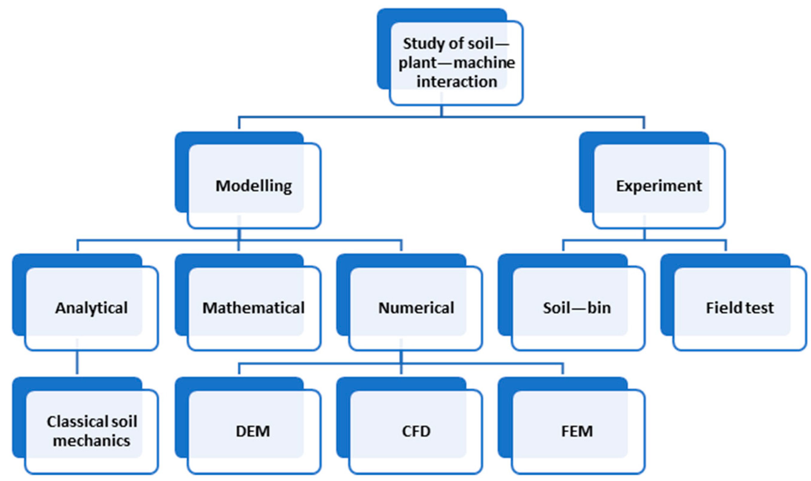
Figure 1. Various methods are used to study the soil–plant–machine interactions.
Agronomy 13 01260 g001
Figure 2. DEM modeling flow chart.
Agronomy 13 01260 g002
Figure 3. Schematic representation of DEM particle contact models: (a) normal (kn: normal stiffness; ηn: normal critical-damping ratio; ΔXn: overlap of two contacting spheres); (b) tangent (ks: tangential stiffness; ηs: shear critical-damping ratio; ΔXs: tangential component of relative displacement; μs: coefficient of friction); and (c) rolling (kr: rotational stiffness; ηr: rolling critical-damping ratio; Δϴ: relative rotation of two contacting particles; μr: coefficient of rolling friction) [28].
Agronomy 13 01260 g003
Figure 4. Classification of contact models and their potential application for agricultural materials in DEM.
Agronomy 13 01260 g004
Figure 5. Typical tillage implements of SPMI studies include: (a) sweep [82]; (b) subsoiler [85]; (c) wide cutting blade [86]; (d) moldboard plow [79]; (e) rotary blade [75]; and (f) straw-sweep [83].
Agronomy 13 01260 g005
Figure 6. DEM simulations of seeding and planting implements: (a) seed-metering process [94]; (b) soybean planting machine [95].
Agronomy 13 01260 g006aAgronomy 13 01260 g006b
Figure 7. DEM modeling of (a) fertilizer surface application [105] and (b) deep application (in the left image: 1: starter fertilizer compartment, 2: starter fertilizer, 3: fluted roller, 4: starter fertilizer collection box, 5: monitoring zone for starter fertilizer, 6: monitoring zone for base fertilizer, 7: base fertilizer collection box, 8: base fertilizer, 9: base fertilizer compartment; in the right image: 1: base fertilizer, 2: starter fertilizer, 3: soil particles, 4: soil bin) [101].
Agronomy 13 01260 g007
Figure 8. DEM modeling of harvesting machines and process of (a) grain crops [110]; (b) root crops [115]; (c) stalks [111]; and (d) leaves [114].
Agronomy 13 01260 g008aAgronomy 13 01260 g008b
Table 2. Range of parameters used for soil–plant–machine interaction in seeding and planting applications.
ParametersSoil c–gPlant a–h 1–5Machine a,c,e–g
Particle size (mm)2–101–30-
Particle density (kg m−3)1380–2680215–12807800–7900
Shear modulus of particle (MPa)1–1001–76070,000–79,000
Poisson’s ratio of particle0.2–0.390.2464–0.40.3–0.35
Coefficient of restitution0.15–0.750.175–0.6680.2–0.627
Coefficient of friction0.1–0.90.0338–0.80.2–1.2
Coefficient of rolling friction0.05–0.70.0021–0.07820.01–0.4
Note: Superscripts indicate the source of data: a [96]; b [64]; c [84]; d [77]; e [95]; f [49]; g [97]; h [100]; Subscripts indicate the materials included: 1 Maize seed; 2 Wheat seed; 3 Soybean seed; 4 Root; 5 Sugarcane billet.
Disclaimer/Publisher’s Note: The statements, opinions and data contained in all publications are solely those of the individual author(s) and contributor(s) and not of MDPI and/or the editor(s). MDPI and/or the editor(s) disclaim responsibility for any injury to people or property resulting from any ideas, methods, instructions or products referred to in the content.