Article

Design and Experiment of an Unmanned Variable-Rate Fertilization Control System with Self-Calibration of Fertilizer Discharging Shaft Speed

by
Yuanyuan Gao
1,2,
Kangyao Feng
1,
Shuo Yang
3,
Xing Han
1,
Xinhua Wei
2,*,
Qingzhen Zhu
1,2 and
Liping Chen
1,3,*
1
School of Agricultural Engineering, Jiangsu University, Zhenjiang 212013, China
2
Key Laboratory of Modern Agricultural Equipment and Technology, Ministry of Education, Zhenjiang 212013, China
3
National Engineering Research Center for Information Technology in Agriculture, Beijing 100097, China
*
Authors to whom correspondence should be addressed.
Agronomy 2024, 14(10), 2336; https://doi.org/10.3390/agronomy14102336
Submission received: 16 August 2024 / Revised: 8 October 2024 / Accepted: 9 October 2024 / Published: 10 October 2024
(This article belongs to the Special Issue AI, Sensors and Robotics for Smart Agriculture—2nd Edition)

Abstract

:
In response to the problems of low control accuracy, single detection of operating parameters, and insufficient collaborative control of unmanned fertilization in field fertilization operations, this paper proposes an adaptive control strategy for fertilizer discharging shaft speed based on segmented linear interpolation method. By constructing a relationship model between fertilizer discharging shaft speed and motor control signals in different speed ranges, the on-site self-calibration of fertilizer discharging shaft speed and the precise control of the fertilization rate is achieved. At the same time, real-time detection and warning technology for multiple working condition parameters were integrated, and a bus communication protocol between unmanned tractors and variable-rate fertilizer applicators was developed. A variable-ratefertilization monitoring system based on unmanned tractors was developed, and actual experimental tests were conducted to test the system’s performance. Among them, the calibration test results of fertilization rate showed that the discharging rate of the fertilizer apparatuses (p) was negatively correlated with the rotation speed of the fertilizer discharging shaft, and that the installation position of the fertilizer apparatuses affected the uniformity of fertilization between the rows of the fertilizer applicator. The speed response test of the fertilizer discharging shaft showed that the average response time (Ts) of the fertilizer discharging shaft speed controlled by the self-calibration model was 0.40 s, the average steady-state error (ess) was 0.13 r/min, and the average overshoot (σ) was 7.33%. Compared with the original linear model, the ess was reduced by 0.23 r/min, and the σ was reduced by 1.54 percentage points. The results of the fertilization status detection tests showed that the system can achieve real-time detection of different operating parameters and states, as well as collaborative control of tractors and fertilizer applicators. The results of the fertilization rate control accuracy test showed that the average fertilization control error of the system was 1.91% under different target fertilization rate, which meets the requirements of variable-rate fertilization field operations. This study can serve as a technical reference for the design and development of fertilization robots in the context of unmanned farm development.

1. Introduction

Fertilizer, as one of the most important fundamental materials in agricultural production, plays a crucial role in ensuring food security and achieving high efficiency and yields in agriculture. Scientific fertilization methods contribute to enhancing agricultural production efficiency and improving the quality of agricultural products [1]. Precision variable fertilization technology can apply fertilizers according to the required amount based on the soil nutrient status [2], which offers a significant advantage over traditional methods of manual broadcasting or uniform fertilization. By reducing fertilizer usage and environmental pollution, fertilizer use efficiency and production effectiveness are increased. This technology serves as an essential support for the continuous and steady advancement of the national initiative to reduce fertilizer use while increasing efficiency. As a key element of variable-rate fertilization technology, the variable-rate fertilizer applicator operates by driving the fertilizer apparatus through a fertilizer discharging shaft and delivering granular fertilizer from the hopper into the soil at a specified depth through the fertilizer pipe [3]. The performance of this equipment directly affects the final fertilization outcome.
Currently, the development of variable-rate fertilization technology is relatively mature both domestically and internationally, with various types of variable-rate fertilizer applicators achieving different levels of market adoption [4]. However, there is still room for improvement in the precision of fertilizer application and the degree of system intelligence [5]. Consequently, scholars worldwide have conducted extensive research on the precise control of fertilizer apparatuses, real-time detection of fertilization rates, and online monitoring of operational conditions.
As a key component of the fertilizer applicator, the structural parameters of the fertilizer apparatuses directly affect the stability of fertilizer distribution [6]. By using simulation software to model the movement of fertilizer within the fertilizer apparatuses, the structural parameters of the fertilizer apparatuses can be quickly optimized [7]. For example, Zhang et al. [8] performed discrete element simulation on the widely-used external groove wheel-type fertilizer apparatuses and found that the factors affecting fertilizer performance are, in order of importance, groove shape, effective groove length, fertilizer discharging shaft speed, and the opening of the fertilizer outlet. The optimal groove shape was identified as having a helix angle of 75° for the best fertilizer performance.
On the other hand, for distributors with fixed structural fertilizer apparatuses, Shi et al. [9] discovered that improving the control strategy could enhance the stability of the fertilizer apparatuses. Zhang et al. [10,11] studied the influence of the fertilizer outlet opening and fertilizer discharging shaft speed on the stability of fertilizer application and found that when the target fertilization rate is relatively small, adjusting the control sequence of the fertilizer outlet opening and fertilizer discharging shaft speed significantly improved distribution stability.
However, existing variable-rate fertilizer applicators primarily rely on ground wheel motion to drive the fertilizer discharging shaft, making the control of the shaft speed susceptible to factors such as wheel slip, resulting in uneven fertilization. Using an electric motor to drive the fertilizer discharging shaft can significantly enhance the precision of fertilizer discharging shaft speed control. For instance, the electric fertilizer distribution device developed by Zhao et al. [12] can adjust the fertilizer discharging shaft speed in real time based on vehicle speed, effectively addressing issues associated with traditional ground wheel-driven systems. Nevertheless, fluctuations in vehicle speed may cause pulsations in the fertilizer discharging shaft speed.
To achieve stable control of the fertilizer discharging motor, several studies [13,14,15] have established fuzzy control rules and optimized the PID parameters of the control motor using a fuzzy controller. Zhu et al. [16] employed a particle swarm optimization algorithm and control system tuner toolbox to improve the accuracy of control parameters for the fertilizer distribution system. Due to differences in distributor structures and fertilizer apparatuses characteristics across different applicators, control methods with fixed parameters may not provide optimal adaptability, and the accuracy of fertilizer discharging shaft speed control still requires further improvement.
On the other hand, real-time detection of the fertilization rate is the foundation for precise control of the fertilization rate. Current detection methods for the fertilization rate can be broadly categorized into direct and indirect methods. Direct methods involve the use of non-contact sensors, such as capacitive sensors or microwave sensors installed inside the fertilizer tubes, to detect the real-time fertilizer flow [17,18,19,20]. These methods offer high detection accuracy and good real-time performance, but have high requirements for the working environment and are susceptible to interference from factors such as fertilizer adhesion or dust inside the tubes. Indirect methods, on the other hand, typically involve detecting the real-time speed of the fertilizer discharging shaft [21].
By combining a theoretical analysis of fertilizer tube flow with dynamic calibration methods for the fertilizer apparatuses, a fertilizer flow detection model can be constructed, which allows for online monitoring of the fertilization rate. These indirect methods are more reliable in complex working environments, and are commonly used in practical applications. With the advancement of technologies such as autonomous driving and smart farming [22,23,24], the research and development of high-quality and efficient fertilization robots have become a current trend.
A practical and feasible approach to implementing fertilization robots is the combination of unmanned tractors and variable-rate fertilizer applicators [25], which also raises the demand for monitoring the operational conditions of the machinery. Scholars have researched various operational parameters, such as fertilizer tube blockage [26], fertilizer box residue [27], and operating speed [28], but these studies often focus on individual parameters and lack integrated, multi-parameter monitoring systems. Additionally, there has been limited research on the coordinated control between tractors and fertilizer applicators, with a notable absence of a unified data communication protocol between them.
In response to the above issues, the specific objectives of this study were (1) to propose a self-calibration and control method for fertilizer discharging shaft speed suitable for different fertilizer discharge devices based on unmanned tractor technology; (2) to develop a bus communication protocol between unmanned tractors and fertilizer applicators, and develop a variable-rate fertilization monitoring system by integrating real-time detection and alarm technology for multiple operating parameters; (3) to explore the relationship between the discharging rate of fertilizer apparatuses and the rotational speed and position of the fertilizer discharging shaft, providing theoretical support for the subsequent improvement of fertilizer apparatuses; and (4) to conduct practical experiments to test the system’s performance.

2. Materials and Methods

2.1. Systems Design

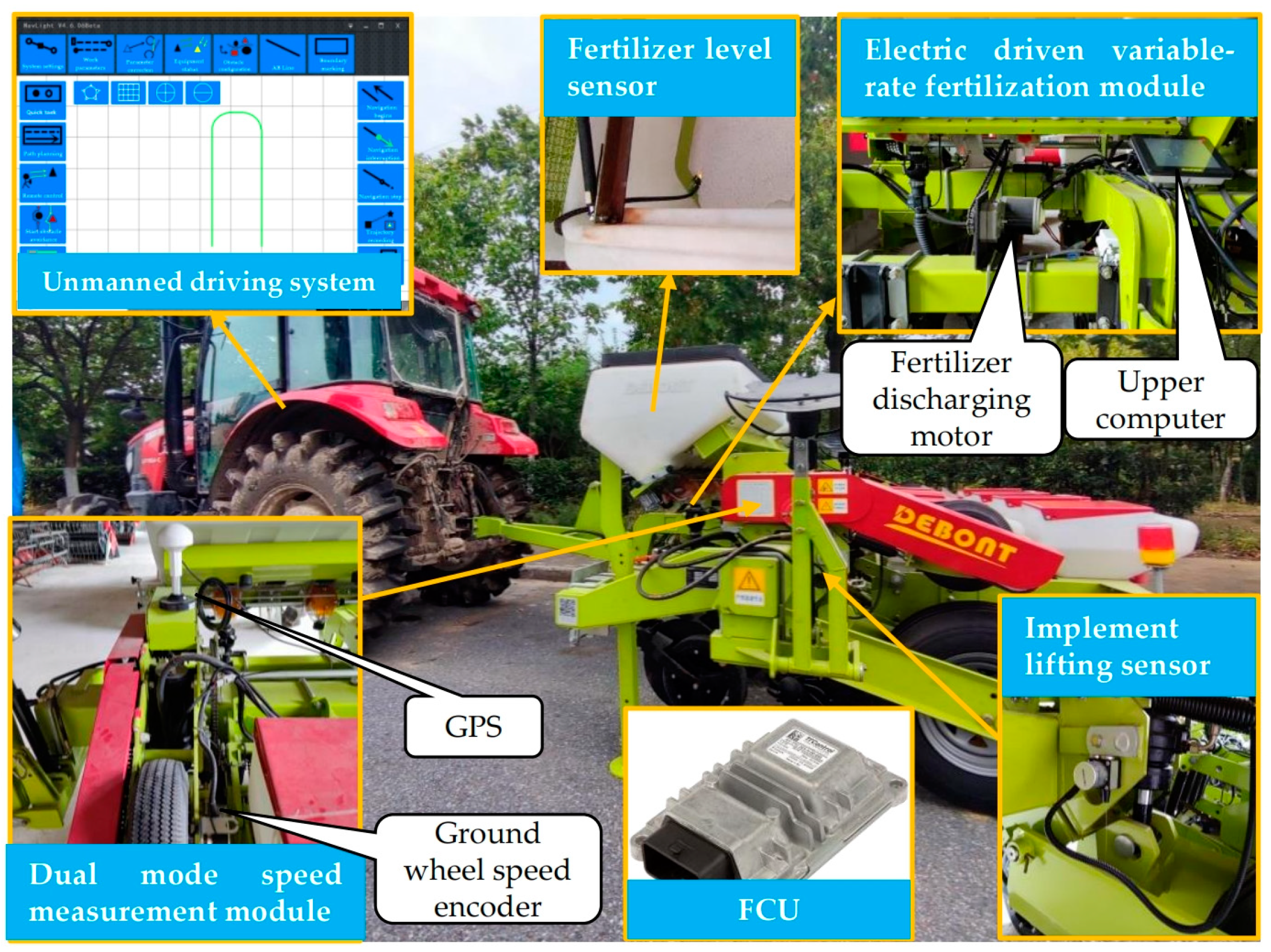
2.1.1. System Composition and Working Principle

The fertilization device is a traction-type sowing and fertilizing machine (1405, DEBONT Corp., Beijing, China) matched with the Dongfanghong LF1104 tractor (YTO Co., Ltd., Luoyang, China), mainly used for no-tillage sowing and fertilization under full straw cover conditions and conventional operations involving corn or soybeans. The composition of the unmanned variable-rate fertilization control system is shown in Figure 1, mainly consisting of an unmanned fertilization module, an operation parameter detection module, and a variable-rate fertilization monitoring module.
The unmanned fertilization module consists of an unmanned driving system for tractors, a variable-rate fertilization device and a ground wheel lifting device. Among them, the unmanned driving system for tractors is based on the system developed by the research group in the early stage, integrating fertilization operation control, which can achieve functions such as unmanned driving, path tracking, and collaborative control with the fertilizer applicator. The variable-rate fertilization device includes components such as a DC motor, motor driver, gear, chain, etc. It adopts motor drive and chain transmission methods, and replaces the original ground wheel-driven fertilizer discharging shaft rotation with a motor-driven system, allowing for real-time adjustment of the fertilization rate. The ground wheel lifting device mainly consists of a tool-lifting sensor and a tool-lifting device. The tool-lifting device is installed on the ground wheel bracket and connected to the hydraulic distributor of the tractor. It can control the extension and retraction of the ground wheel cylinder based on the working status of the tool and the ground wheel height information feedback from the tool-lifting sensor, achieving the lifting and lowering of the fertilizer applicator.
The operation parameter detection module includes a fertilizer bin level sensor, a fertilizer pipe blockage detection sensor, an implement-lifting sensor, and a dual-mode vehicle speed measurement device. The fertilizer level sensor (NA-Q2010NO, Shenzhen Jaruisi Technology Co., Ltd., Shenzhen, China) uses a square capacitive proximity switch to detect the remaining amount of fertilizer in the fertilizer box. By changing its installation height on the inner wall of the fertilizer box, the fertilizer threshold alarm can be adjusted. The fertilizer pipe blockage detection sensor (Donggang Xinxing Electronic Seeder Factory, Donggang, China) is fixed below the overflow fertilizer gourd. It adopts the principle of photoelectric reflection and collects the flow of fertilizer inside the fertilizer pipe through multiple photodiodes. When the fertilizer pipe is blocked, it triggers the output of a high level and resets after a delay of 3.5 s. The implement lifting sensor (MPS-XS-120mm-V1, Shenzhen Miran Technology Co., Ltd., Shenzhen, China) is installed on the ground wheel bracket and uses a cable sensor to detect the lifting position of the tool. The dual-mode vehicle speed measurement device includes a GPS speed measurement module (National Engineering Research Center for Information Technology in Agriculture) and an incremental photoelectric encoder (GK80K25G1024BMC526, Shenzhen Quankong Optoelectronic Technology Co., Ltd., Shenzhen, China). The GPS speed measurement module can convert speed signals into frequency signals, with a speed measurement range of 1.8~130 km/h. The encoder is installed on the rotating shaft of the ground wheel, with a maximum response frequency of 100 KHz, and measures the speed of the ground wheel through pulse output, thereby achieving accurate measurement of the operating speed of the fertilizer applicator under high- and low-speed conditions.
The variable-rate fertilization monitoring module includes FCU, the on-board tablet computer, and a battery. The FCU (TTC-32, HYDAC Technology Co., Ltd., Shanghai, China) includes 2 CAN bus communication interfaces and multiple I/O ports, which can collect signals, such as the lifting position of the implement and the remaining amount in the fertilizer box, and control the fertilization rate of the fertilizer applicator in real -time according to the implement’s vehicle speed. The on-board tablet computer (PPC-GS 1501T-JK4 model, Shenzhen Geshem Technology Co., Ltd., Shenzhen, China) installed with the Windows 10 operating system can display real-time information, such as fertilizer machine speed, ground wheel lifting position, single row fertilizer pipe blockage, and fertilizer box remaining capacity. FCU communicates with the onboard computer through the CAN bus, and the PC and FCU are connected through a USB/CAN converter (Isolation type, Beijing Ledian Xinnan Technology Co., Ltd., Beijing, China).

2.1.2. Unmanned Driving System for Tractors

The unmanned driving system developed by the research group in the initial stage is used to carry out electronic control transformation of the tractor, The improved unmanned tractor is shown in Figure 2, which includes the dual antenna RTK positioning and orientation system (Beijing BDStar Navigation Co., Ltd., Beijing, China), a steering drive unit (EMS2, Shanghai AllyNav Technology Co., Ltd., Shanghai, China), a front wheel steering angle sensor (DWOCAB-V-CH, Beijing Tianhaike Technology Development Co., Ltd., Beijing, China), and a universal autonomous navigation control unit (NCU) based on STM32F429 chip (STMicroelectronics, Geneva, Switzerland), with the RTK positioning and orientation system installed above the center of the rear axle of the tractor cab to record the tractor’s driving trajectory. The upper computer software was developed based on the Qt environment, and has functions such as AB line navigation, path tracking, whole field navigation, and trajectory storage. In addition, it can also perform the on/off and reversing control of the tractor’s hydraulic distributor, laying the foundation for the subsequent autonomous lifting of ground wheels and the unmanned fertilization operations of the machine.

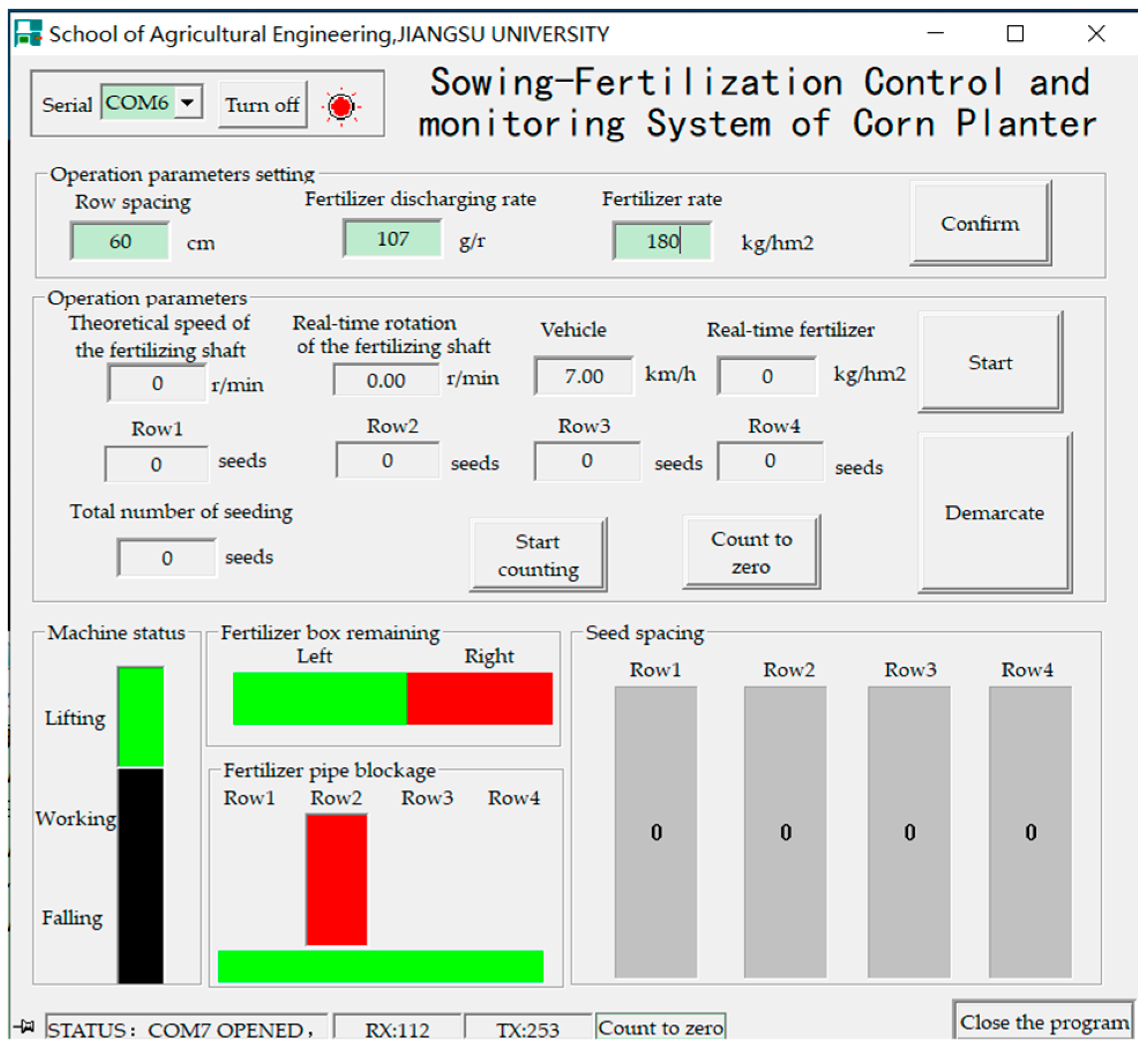
2.1.3. Variable-Rate Fertilization Control System

The interactive interface of the variable fertilization control system developed using the C++ language is shown in Figure 3, which includes modules such as communication serial port settings, operation parameters settings, operation parameters displays, machine status displays, fertilizer box remaining monitoring, fertilizer pipe blockage monitoring, and seed spacing monitoring.
The operation parameters setting module is used to communicate the desired row spacing to the fertilization machine, the target fertilization rate, as well as the fertilization calibration parameters to the FCU in the form of CAN messages for subsequent precise fertilization control. The status of the machine can be divided into lifting, falling, and working states based on the lifting status of the fertilizer applicator. The working status indicates that the machine is in the process of lifting or falling, and the lifting status indicates that the fertilizer applicator has been fully lifted and the tractor can tow it away from the plot. The falling status indicates that the fertilizer applicator has completed its descent and is in the preparation stage for operation. Fertilizer box and pipe monitoring are used to monitor the fertilizer status inside the fertilizer box and fertilizer pipe. When the fertilization amount in the left and right fertilizer boxes is insufficient or the fertilizer pipe is blocked, the color block in the interface will turn red as a warning. The seed spacing monitoring module can display the seed spacing of different rows based on the seeding interval in the seeding tube and the real-time vehicle speed. The operation parameters display module can display the vehicle speed, the theoretical and real-time rotational speed of the fertilizer discharging shaft, as well as the fertilization rate and the number of seeds in different rows in real time.
Among them, the detection of the fertilization rate is crucial for crop management in later stages. To ensure the reliability of sensor detection under complex working conditions, the indirect measurement method is preferred for application in this system, as it detects the fertilization rate based on the real-time speed of the fertilizer discharging shaft and the calibration coefficient of the fertilizer apparatuses. Since the fertilizer apparatuses are driven by a single fertilizer discharging shaft, the drive method for the fertilizer discharging shaft has been improved to be motor-driven system. According to the working principle of variable-rate fertilization, it can be concluded that
1000 v 60 × w 10,000 × q t = N t × p k 1000
Therefore, the speed of the motor is
N t = 5 v w q t 3 p k
where:
Nt is the target speed of the fertilizer discharging shaft, r/min;
v is the vehicle speed, km/h;
w is the width of the fertilizer applicator, m, which is equal to 2.4;
qt is the target value for the fertilization rate, kg/hm2;
p is the fertilizer discharging rate, which represents the amount of fertilizer discharged per rotation of a single fertilizer apparatus, g/r;
and k is the number of fertilizer apparatuses in operation, which is equal to 4.
At the same time, a Hall encoder is installed at the rear of the fertilization motor to provide feedback on the motor speed and frequency. Due to the motor transmitting power to the fertilizer discharging shaft through a reducer and sprocket chain, the speed of the fertilizer discharging shaft is
N a = f m P · i t · i m
where:
Na is the actual speed of the fertilizer discharging shaft, r/min;
fm is the feedback frequency of the motor speed, Hz;
P is the encoder resolution, plus/r, which is equal to 6;
it is the chain transmission ratio, which is equal to 17/25;
and im is the reduction ratio of the motor reducer, which is equal to 56.
Therefore, the value of p can be obtained by calibrating the fertilizer discharging rate of the fertilizer apparatus. Combined with Equations (2) and (3), the target speed of the fertilizer motor can be calculated, thereby achieving variable-rate fertilization and real-time online detection of the fertilization rate.
In addition, during the operation of the fertilizer discharging motor, its starting torque is affected by factors such as the structure of the fertilizer apparatuses, the number of fertilizer rows, and the physical properties of the fertilizer. Only when the output torque is greater than the resistance torque of the fertilizer discharging shaft rotation can the fertilizer discharging shaft drive the fertilizer apparatuses to work stably, thereby reducing the occurrence of fertilizer pulsation caused by sudden changes in motor speed. Thus, a fertilizer discharging calibration function was designed as shown in Figure 4, which can achieve the self-calibration of motor speed by fitting the drive curve of the fertilizer discharging motor. This method can improve the control accuracy of the fertilizer discharging motor and its adaptability to different fertilizer apparatuses.
The parameters setting interface includes simulated voltage initial value Vi, simulated voltage peak value Vp, and conversion coefficient Kv, where Vi represents the simulated voltage value at the lowest stable speed of the fertilizer discharging shaft, Vp represents the minimum simulated voltage value of the driving motor required at the highest stable speed of the fertilizer discharging motor, and Kv represents the conversion coefficient between the motor speed feedback frequency and the fertilizer discharging shaft speed, which is related to the resolution of the motor encoder and the reduction ratio between the motor and the fertilizer discharging shaft. The calculation formula is as follows.
K v = P · i t · i m
According to Equation (4), Kv can be calculated as 229. Furthermore, the required driving voltage for starting the fertilizer discharge motor (Vi) is 900 mV, and the driving voltage during peak rotation (Vp) is 4900 mV.

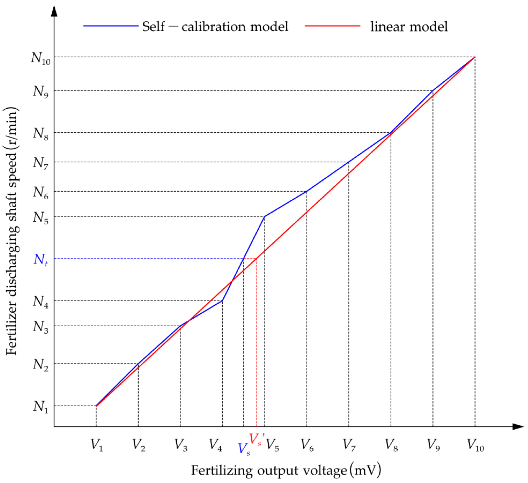
2.1.4. Design of Self-Calibration Program for the Fertilizer Discharging Shaft Speed

To reduce the influence of factors such as the structure of the fertilizer apparatus on the output speed of the fertilizer discharging motor and improve the accuracy of fertilizer discharging control, a segmented linear interpolation method was used to construct a relationship model between the speed of the fertilizer discharging shaft and the output signal of the FCU. Firstly, the PC sends three calibration parameters (as shown in Figure 4), including the initial value of the simulated voltage, to the FCU in the form of a CAN-bus message. After parsing the message data, the FCU divides the obtained simulated voltage adjustment range into 11 intervals and outputs them in sequence to drive the fertilizer discharging motor to rotate. At the same time, the FCU collects the fertilizer discharging motor speed in real time and sends it to the PC one by one in the form of a CAN-bus message. Then, based on the driving voltage signal value and the corresponding speed value of the fertilizer discharging shaft, the PC establishes a linear segmented relationship model between the fertilizer discharging shaft speed and the driving simulation voltage (as shown in Figure 5). Finally, with the target speed (Nt)of the fertilizer discharging shaft as the independent variable and the corresponding driving output voltage Vs as the dependent variable, the following equation was established.
V s = V 1 N t N 1 V s = k n N t + b n N n < N t N n + 1 V s = V 10 N t > N 10
where kn and bn (n = 1, 2, 3, …, 9) are the slope and intercept of the corresponding model, respectively. The specific calculation equations are as follows.
V n + 1 = V n + d
d = V 10 V 1 10 = V p V i 10
k n = V n + 1 V n N n + 1 N n b n = N n + 1 V n N n V n + 1 N n + 1 N n
The relationship model between the target speed of the fertilizer discharging motor and the driving voltage can be obtained by combining Equations (5)–(8). On this basis, the target rotational speed (Nt) is calculated based on the vehicle speed and the set value of the fertilization rate. Then, according to Equation (5), the linear region where Nt is located is determined, and the driving output voltage (Vs) is calculated. From the model comparison in Figure 5, compared to the unimproved linear control model, the self-calibration control model can ensure precise speed control of the fertilizer discharging shaft at different target rotational speeds.

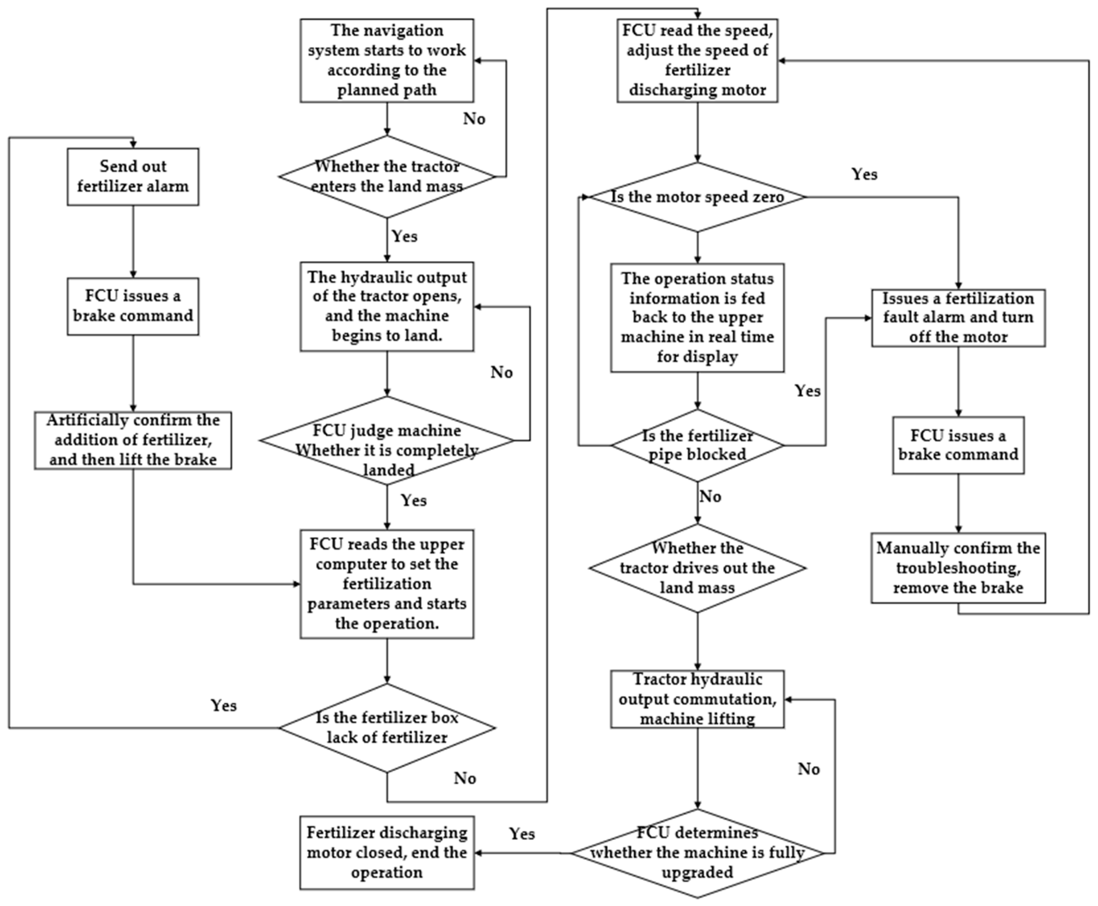
2.1.5. System Workflow

After completing the calibration of the fertilizer motor speed and the planning path of the fertilizer applicator, the fertilizer applicator enters the work field under the traction of an unmanned tractor. When the fertilizer applicator reaches the set location, the navigation system controls the opening of the tractor hydraulic distributor oil circuit to lift the ground wheel until the fertilizer applicator is fully grounded and in working condition. At this point, the FCU detects and sends instructions to the navigation system to close the hydraulic oil circuit, then reads the fertilization parameters set by the upper computer. Finally, the tractor pulls the fertilizer applicator to start working.
During this process, when the FCU detects insufficient fertilizer in the fertilizer box, clogged fertilizer pipes, zero motor speed and non-zero vehicle speed, etc., it sends a brake command to the navigation system until manually confirming the addition of fertilizer or troubleshooting before continuing to work. When the navigation system detects that the tractor has driven out of the field, it begins to control the hydraulic distributor oil circuit of the tractor to change direction, reducing the height of the ground wheel until the fertilizer applicator is in a fully raised state. At this point, the FCU commands the fertilizer discharging motor to stop working, and the tractor drives the fertilizer applicator away from the field (as shown in Figure 6).
To achieve collaborative control between tractors and fertilizer applicators, a data communication protocol based on the “ISO 11783 standards [29] has been developed, and a Protocol data unit (PDU) has been adopted to standardize the information frame format. It mainly consists of the following components: priority (P), extended data page (EDP), data page (DP), PDU format (PF), specific PDU (PS), source address (SA), and data field (DATA). Among them, P, EDP, DP, PF, and PS constitute the parameter group numbers (PGNs) of the message, which are used to identify the content and type of PDU. The formulation of the CAN-bus communication protocol is to assign unique PGNs to different messages. Referring to the communication standards for the application layer of machine messages, a protocol for parameter messages related to fertilizer applicators has been developed, as shown in Table 1.

2.2. Test Method

2.2.1. Calibration Test of Fertilization Amount

The accuracy of fertilization rate detection is affected by the stability of the fertilizer apparatus, and it is necessary to conduct a calibration test on the fertilizer apparatus. As shown in Figure 7, before the experiment began, the sizes of the fertilizer inlet and outlet of all the fertilizer apparatuses were adjusted to be consistent and the fertilizer (K2SO4 slow-controlled fertilizer, Jiyuan Fengtian Fertilizer Co., Ltd., Jiyuan, China) was poured into the left and right fertilizer boxes of the fertilizer applicator until the bottom fertilizer outlet was completely covered. This fertilizer meets the requirements of the National Standards for mixed fertilizers, with a particle size greater than 90% and a moisture content of less than 2%. Then, four plastic buckets were weighed and placed at the outlet of each fertilizer pipe. According to the actual work requirements and the speed range of the fertilizer discharging shaft, the fertilizer discharging speed was set to 15, 30, and 45 r/min. After the fertilizer discharging shaft rotated stably for 10 revolutions, the mass of fertilizer in the plastic bucket was collected and weighed. After repeating the above experiment three times, the amount of fertilizer discharged per rotation of different rows was counted, and the coefficient of variation of fertilizer uniformity was used as a measurement indicator to analyze the uniformity of fertilizer discharge in each row of the variable-rate fertilization device. The equations are as follows:
x ¯ = i = 1 k x i k
S = i = 1 k ( x i x ¯ ) 2 k 1
V = S x ¯ × 100 %
where:
xi is the average fertilization rate (p) of each fertilizer apparatus, g/r;
x ¯ is the average fertilization rate (p) of four fertilizer apparatuses, g/r;
S is the standard deviation of fertilizer uniformity, g/r;
and V is the coefficient of variation of fertilizer uniformity, %.

2.2.2. Speed Response Test of Fertilizer Discharging Motor

After the calibration test of the fertilization rate of the fertilizer apparatus, the control performance of the fertilizer discharging motor was tested under different vehicle speeds to test the effectiveness of the system in controlling the motor speed and to verify the reliability of the proposed control method. Before the experiment began, the fertilization rate was set to 225 kg/hm2, and the fertilization parameters obtained from the above calibration test were input into the system. The fertilizer was evenly filled into the left and right fertilizer boxes, and three different vehicle speeds (4, 6, and 8 km/h) were simulated by using a frequency generator. The USB/CAN-E-U analyzer (Zhuhai Chuangxin Technology Co., Ltd., Zhuhai, China) was used to record the feedback data of the fertilizer discharging motor speed within 4 s at a sampling frequency of 10 Hz. At the same time, the speeds of the fertilizer discharging motor without speed calibration were compared, and the step response characteristics of fertilizer discharging control were analyzed. The evaluation indicators used include steady-state error (ess), overshoot (σ), and response time (Ts), which is the time required to reach the steady-state value within a 5% error range.
σ = y ( t p ) y ( ) y ( ) × 100 % e s s = y ( ) N t
where:
σ is the overshoot of speed control, %;
y(tp) is the peak speed, r/min;
y() is the steady-state value of rotational speed, r/min;
ess is the steady-state error of speed control, r/min;
and Nt is the target speed, r/min.

2.2.3. Fertilization Status Detection Test

As shown in Figure 8a, to test the accuracy of feedback on the working status information from the unmanned fertilizer applicator, fertilization status detection tests were carried out, including fertilizer box level detection, fertilizer pipe blockage detection, seeding amount detection, and machine lifting detection. Firstly, based on the installation position of the level detection sensor, the remaining fertilizer in the fertilizer box was changed to observe the feedback of the upper computer’s fertilizer remaining amount alarm. The experiment was repeated 10 times and the results were analyzed. Then, the fertilization monitoring system began to fertilize, and the lower end of the fertilizer pipe was manually sealed in a blocked state, with 20 blockages per row, and the accuracy of fertilizer pipe blockage detection was observed and counted in the upper computer. At the same time, 200 seeds were placed into the four rows of seed guide tubes, and the number of seeds dropped was observed for each row of the upper computer interface to calculate the accuracy of seed drop detection. Finally, the machine status display was observed to ensure its accuracy by controlling the opening and closing of the tractor hydraulic valve to adjust the height of the fertilizer applicator’s ground wheel.

2.2.4. Fertilization Amount Control Accuracy Test

As shown in Figure 8b, to test the dynamic performance of the system in the field, a fertilization rate control accuracy test was conducted at the Jiangsu Runguo Efficient Ecological Agriculture Base. Referring to the testing methods of national standards GB/T 35487-2017 [30], the fertilization rates were set to 150, 225, and 300 kg/hm2, respectively. The tractor was controlled so as to travel steadily for about 40 m, and the fertilizer mass under the four rows of fertilizer pipes was manually collected and weighed. The actual fertilization rate was calculated based on the actual forward distance of the equipment and the operating width. After repeating each experiment three times, the control error (δ) of fertilization rate was calculated according to the following equation.
δ = q a q t q t × 100 % = m 10 w l q t 10 w l q t
where:
qt is the set value of fertilization rate, kg/hm2;
qa is the actual value of fertilization rate, kg/hm2;
l is the actual forward distance of the fertilizer applicator, m;
and m is the weight of fertilizer dropped by the fertilizer applicator, g.

3. Results

3.1. Calibration Test Results of Fertilization Amount

The results of the fertilization rate calibration test are shown in Table 2. At different target speeds, the average discharge rate of the four fertilizer apparatuses driven by the fertilizer discharging shaft decreased from 121.35 g/r at 15 r/min to 99.29 g/r at 45 r/min. This means that the discharge rate of the fertilizer apparatus is negatively correlated with its speed. It may be that the excessively high speed affects the filling effect of fertilizer in the fertilizer apparatus. Optimizing and adjusting the opening of the fertilizer apparatus and the speed of the fertilizer discharging shaft are two variables that can help improve the accuracy of the fertilization rate control. When the size of the fertilizer outlet cannot be adjusted, it is possible to consider establishing a relationship model between the discharge rate and the rotational speed of the fertilizer apparatus. During the operation, the discharge rate can be adaptively matched according to the target rotational speed of the fertilizer discharging shaft, thereby promoting precise fertilizer application.
Further analysis reveals that under the same rotational speed, there is a significant change in the discharge rate of different rows. Especially for the same fertilizer box, the discharge rate of the outer fertilizer apparatus is significantly greater than that of the inner fertilizer apparatus; that is, the discharge rates of rows 1 and 4 are higher than that of rows 2 and 3. The reason for this may be related to the installation position of the fertilizer apparatuses in the fertilizer box. The fertilizer apparatuses in rows 2 and 3 are both installed at the edge of the fertilizer box, and the filling effect of the fertilizer is affected by the inner wall of the fertilizer box. Compared to the fertilizer apparatuses in rows 1 and 4, which are installed near the middle of the fertilizer box, the stability of the fertilizer supply at the inlet is better.
In addition, at different rotational speeds, the average standard deviation of the discharge rate of the four fertilizer apparatuses is 18.21 g/r, and the coefficient of variation of the discharge rate in each row is smallest at 15 r/min, at 15.72%, and the largest at 30 r/min, at 17.44%. This also indicates that the differences in discharge rates among different fertilizer apparatuses are not only related to their structural characteristics but also influenced by the filling effect of fertilizers. Working at low speeds can reduce the differences in fertilizer discharging performance between different fertilizer apparatuses, while the fertilizer filling effect of each fertilizer apparatus is significantly reduced at high speeds. However, compared to medium speeds (30 r/min), the coefficient of variation between them is reduced to 15.90%. Therefore, discharging fertilizers at both high and low speeds helps to improve the uniformity of fertilizer distribution in the soil.
According to the above analysis, the fertilization rate in different rows is affected by the installation position of the fertilizer apparatus. Due to the fixed and inconvenient installation position of the fertilizer apparatus in this system, to improve the uniformity of fertilizer application in each row, the opening of the fertilizer inlet of the fertilizer apparatus in different rows is adjusted to reduce the difference in discharge rate between rows. After adjusting the opening, the discharge rate was tested at different rotational speeds, and the results are shown in Figure 9. The relationship model between the discharge rate of the fertilizer apparatus and the speed of the fertilizer discharging shaft is established as follows.
p = 0.2624 N t + 113.34
The determination coefficient (R2) of the model is 0.91, and the root mean square error (RMSE) is 1.06, indicating a good linear relationship between the rotational speed of the fertilizer discharging shaft and the fertilizer discharging rate. By combining Equations (2) and (14), the appropriate speed of the fertilizer discharging shaft can be determined during variable-rate fertilization, thereby reducing the control error of fertilizer application.

3.2. Speed Response Test Results of Fertilizer Discharging Motor

Based on the results of the speed control test, the authors drew the step response curve of the fertilizer discharging shaft speed at different vehicle speeds, as shown in Figure 10. As shown in the figure, the self-calibration model exhibits good adaptability and stability at different vehicle speeds. With the increase in vehicle speed, the fluctuation amplitude of fertilizer discharging shaft speed under the self-calibration model control increases, although it can still maintain a small control error and response time. In contrast, the control performance of the linear model significantly decreases at higher vehicle speeds, and the steady-state error also increases significantly. Combined with the principle of self-calibration control of the fertilizer discharging shaft speed, the possible reason is that at the same target speed, the output voltage value of the linear model is too large, resulting in a larger steady-state error of the linear model.
The authors analyzed and quantified the response characteristic indicators shown in the graph, and the results are shown in Table 3. According to the table, the average response time of the fertilizer discharging shaft speed under the self-calibration control is 0.40 s, the average steady-state error is 0.13 r/min, and the average overshoot is 5.79%. The average response time of the fertilizer discharging shaft speed under linear model control is 0.63 s, the average steady-state error is 0.36 r/min, and the average overshoot is 7.33%. The response times of the fertilizer discharging motor under the self-calibration model and linear model control are not significantly different. The reason for this is that the performance of the motor and controller determine the speed response of the output speed. However, compared to the linear model, the steady-state error of the fertilizer discharging motor controlled by the self-calibration model was reduced by 0.23 r/min, and the overshoot was reduced by 1.54 percentage points, indicating that this method has significant advantages in improving fertilizer stability and uniformity.

3.3. Fertilization Status Detection Test Rusults

After measuring the fertilizer level of the left and right fertilizer boxes 10 times, respectively, the upper computer interface achieved real-time detection, including turning green in a normal state and red in case of a fertilizer shortage, with an accuracy rate of 100%. The results of the fertilizer pipe blockage test showed that after manual intervention, the monitoring interfaces of each row would turn red and give an alarm, with an average accuracy rate of 100%. In contrast, the seed drop detection function was limited by seed size and the seed drop time interval, and some seeds were not detected when they fell. The detection errors of the four rows were 0.5%, 1.5%, 1.5%, and 1.0%, respectively, which means the average accuracy of seed amount detection in each row is 98.88%. In addition, the test results of the lifting and lowering status detection of the equipment were normal. As the height of the equipment changes, the interface can accurately reflect the three states of the fertilizer applicator—falling, lifting, and working—achieving the detection of the different operating parameters and states of the fertilizer applicator.

3.4. Fertilization Amount Control Accuracy Test Rusults

The test results for the control accuracy of the fertilization rate are shown in Table 4. Under different fertilizer application rates, the average control error of the fertilization rate was 1.91%, with a minimum of 0.23% under the fertilization rate of 225 kg/hm2 and a maximum of 3.21% under the fertilization rate of 150 kg/hm2. The overall control error meets the requirement for less than 5% specified in the national standards GB/T 35487-2017 [30], indicating that the system meets the application design requirements. In addition, the system control error (2.87%) under the fertilization rate of 150 kg/hm2 was significantly greater than that under the fertilization rate of 225 and 300 kg/hm2, indicating that more accurate fertilization amount control can be achieved at high speeds. This may be due to the shorter adjustment time of the fertilizer discharging shaft speed, especially during variable-rate fertilization, which can ensure the stable application of fertilizer for a longer period.

4. Discussions

The results of the fertilization rate calibration test and the rotation speed response test indicated that the main factors affecting the fertilizer discharging rate are the opening of the fertilizer apparatus and the rotation speed of the fertilizer discharging shaft. The fertilizer discharging rate showed an increasing trend with an increase in the fertilizer apparatus opening or a decrease in the fertilizer discharging shaft speed, and this trend conformed to a linear regression model. This discovery is similar to the conclusions of other similar studies [10], which validated the influence of the combination of fertilizer outlet opening and fertilizer discharging shaft speed on fertilizer discharging performance. However, further analysis revealed that under the same rotational speed, the fertilizer discharging rate from different fertilization rows showed significant changes. In particular, the amount of fertilizer discharged from the outer fertilizer apparatus was significantly greater than that from the inner fertilizer apparatus under the same fertilizer box. The reason for this may be related to the installation position of the fertilizer apparatus in the fertilizer box. The filling effect of the fertilizer inlet was affected by the inner wall of the fertilizer box, which has not received sufficient attention in previous studies. Therefore, we suggest that the installation position of the fertilizer apparatus should be reasonably arranged during the design stage of the fertilizer box so as to reduce its impact and improve the uniformity of fertilization in different operation rows of the fertilizer applicator.
In addition, the results of the speed response test, fertilization status detection test, and fertilization rate control accuracy test indicate that the system meets the requirements for fertilizer discharging operations under unmanned driving conditions. Firstly, the improved system has a lower steady-state error in fertilizer discharging shaft control compared to the linear model, and exhibits good adaptability and stability at different vehicle speeds. Secondly, the detection system can detect different operating parameters and states of the fertilizer applicator. Finally, variable-rate fertilization can be implemented in actual field operations and comply with industry standards. However, it should be pointed out that this study has some further limitations. The experiment did not perform a comparison with the improved systems of existing research [12,14]. In terms of fertilization rate detection, although the indirect measurement method of fertilization rates is more reliable, there is still the problem of low accuracy in measurement, and the integration of the system still needs to be improved. In subsequent research, we should focus on the operational requirements of simultaneous fertilization and seeding, develop high-precision direct detection technology for the fertilization rate, integrate variable-rate seeding technology, coordinate the control of seeding and fertilization, and compare these with existing systems to obtain the optimal control parameters in different environments. Therefore, future research should focus on improving and testing the system, integrating this fertilization system into the overall operation of unmanned farms, and providing technical support for cost savings and efficiency improvements in intelligent and unmanned farms.

5. Conclusions

In response to the problems of low control accuracy in fertilizer quantity regulation, single detection of operating parameters, and insufficient collaborative control of unmanned fertilization in field variable-rate fertilization operations, this paper improves the control method of the fertilizer discharging motor, integrating multi parameter real-time detection and alarm technology, and developing a bus communication protocol suitable for information exchange between tractors and fertilizing applicators. The final design a variable-rate fertilization system with self-calibration function of fertilizer discharging shaft speed.
This system uses a segmented linear interpolation method to construct a model of the relationship between the fertilizer discharging shaft speed and the FCU output signal, achieving local online calibration of the fertilizer discharging shaft speed. Compared with the original control model, the steady-state error is reduced by 0.23 r/min, and the overshoot is reduced by 1.54 percentage points, and the influence of factors such as the structure of the fertilizer apparatuses on the output speed of the fertilizer discharging motor has been reduced, which has improved the control accuracy and response speed of the fertilizer discharging shaft, and is of great significance for achieving high-quality and efficient fertilization operations. At the same time, the integrated parameter detection and information exchange technology for fertilizer box level and other parameters can operate normally in the system, indicating that the system has solved the problem of missed application caused by insufficient or blocked fertilizers, and improved the efficiency of fertilization operations. The field experiments showed that the average fertilization control error under different set fertilization rates was 1.91%, which meets the requirements of variable-rate fertilization in the field.
Although this system has shown good fertilization effects in actual field experiments, it is still limited by the unified driving of the fertilizer apparatuses and the indirect detection of fertilization rate, and there is still room for improvement in precise control of fertilization rate. Future research should focus on the interactive effects of the position, opening, and rotation speed of the fertilizer apparatus, and explore efficient and precise control methods for different rows of fertilizer applicator to achieve the best fertilization effect.

Author Contributions

Conceptualization, Y.G. and X.W.; methodology, Y.G., K.F. and Q.Z.; software, S.Y. and K.F.; validation, Y.G., K.F. and S.Y.; formal analysis, Y.G. and K.F.; investigation, Y.G., K.F., S.Y. and X.H.; resources, Y.G., X.W. and L.C.; data curation, Y.G., K.F. and X.H.; writing—original draft preparation, Y.G. and K.F.; writing—review and editing, X.W. and L.C.; visualization, K.F. and X.H.; supervision, X.W. and L.C.; project administration, X.W. and L.C.; funding acquisition, Y.G. and Q.Z. All authors have read and agreed to the published version of the manuscript.

Funding

This research was funded by the Natural Science Foundation of Jiangsu Province (Grant No. BK20210776 and BK20230548), the National Natural Science Foundation of China (Grant No. 32201672 and No. 32301712), the Postgraduate Research & Practice Innovation Program of Jiangsu Province (Grant No. SJCX24_2402), and the Priority Academic Program Development of Jiangsu Higher Education Institutions (Grant No. PAPD-2023-87).

Data Availability Statement

The data presented in this study are available on request from the corresponding author.

Conflicts of Interest

The authors declare no conflicts of interest.

References

  1. Tang, H.; Wang, J.; Xu, C.; Zhou, W.; Wang, J.; Wang, X. Research progress analysis on key technology of chemical fertilizer reduction and efficiency increase. Trans. Chin. Soc. Agric. Mach. 2019, 50, 1–19. [Google Scholar] [CrossRef]
  2. Rotundo, J.L.; Rech, R.; Cardoso, M.M.; Fang, Y.; Tang, T.; Olson, N.; Pyrik, B.; Conrad, G.; Borras, L.; Mihura, E.; et al. Development of a decision-making application for optimum soybean and maize fertilization strategies in Mato Grosso. Comput. Electron. Agric. 2022, 193, 106659. [Google Scholar] [CrossRef]
  3. Zhang, J.; Liu, G.; Zhang, D.; Jiang, B.; Ren, Z. Research status and prospect on granular fertilizer variable-rate control technology. Jiangsu Agric. Sci. 2022, 50, 69–77. [Google Scholar]
  4. Ren, L.; Tian, M.; Li, J.; Zhan, C. Research status and development analysis of variable fertilization technology in China. J. Agric. Mech. Res. 2023, 45, 10–15. [Google Scholar] [CrossRef]
  5. Zhao, C.; Fan, B.; Li, J.; Feng, Q. Agricultural robots: Technology progress, challenges and trends. Smart Agric. 2023, 5, 1–15. [Google Scholar] [CrossRef]
  6. Liu, X.; Hu, R.; Wang, D.; Lu, B.; Wang, W. Optimization and test of fertilizer apparatus based on granular fertilizer movement model. Trans. Chin. Soc. Agric. Mach. 2021, 52, 85–95. [Google Scholar] [CrossRef]
  7. Dun, G.; Liu, W.; Wu, X.; Mao, N.; Ji, W.; Ma, H. Simulation optimization and experiment of screw extrusion precision fertilizer ejector. J. Jilin Univ. (Eng. Technol. Ed.) 2023, 53, 3026–3037. [Google Scholar] [CrossRef]
  8. Zhang, X. Optimization Design and Key Working Parameters of External trough Wheel Type Fertilizer Effect on Fertilizer Performance. Master’s Thesis, Nanjing Agricultural University, Nanjing, China, 2019. [Google Scholar]
  9. Shi, Y.; Chen, M.; Wang, X.; Odhiambo, M.R.O.; Zhang, Y.; Ding, W. Analysis and experiment of fertilizing performance for precision fertilizer applicator in rice and wheat fields. Trans. Chin. Soc. Agric. Mach. 2017, 48, 97–103. [Google Scholar] [CrossRef]
  10. Zhang, J.; Liu, G.; Hu, H.; Hang, J.; Jiu, Y. Influence of control sequence of spiral fluted roller fertilizer distributer on fertilization performance. Trans. Chin. Soc. Agric. Mach. 2020, 51, 137–144. [Google Scholar] [CrossRef]
  11. Zhang, J.; Liu, G.; Hu, H.; Hang, J. Development of bivariate fertilizer control system via independent control of fertilizing unit. Trans. Chin. Soc. Agric. Eng. 2021, 37, 38–45. [Google Scholar] [CrossRef]
  12. Zhao, S.; Zong, Z.; Liu, G. Design and test on position fertilization control system based on motor drive. Trans. Chin. Soc. Agric. Mach. 2019, 50, 91–95. [Google Scholar] [CrossRef]
  13. Song, X.; Li, H.; Chen, C.; Xia, H.; Zhang, Z.; Tang, P. Design and experimental testing of a control system for a solid-fertilizer-dissolving device based on fuzzy PID. Agriculture 2022, 12, 1382. [Google Scholar] [CrossRef]
  14. Zhang, J.; Yan, S.; Ji, W.; Zhu, B.; Zheng, P. Precision fertilization control system research for solid fertilizers based on incremental PID control algorithm. Trans. Chin. Soc. Agric. Mach. 2021, 52, 99–106. [Google Scholar] [CrossRef]
  15. Bai, J.; Tian, M.; Li, J. Analysis and precision test of variable fertilization control system. J. Agric. Mech. Res. 2022, 44, 22–28. [Google Scholar] [CrossRef]
  16. Zhu, Q.; Zhu, Z.; Zhang, H.; Gao, Y.; Chen, L. Design of an electronically controlled fertilization system for an air-assisted side-deep fertilization machine. Agriculture 2023, 13, 2210. [Google Scholar] [CrossRef]
  17. Akhter, Z.; Taha, W.; Rahman, M.S.U.; Abou-Khousa, M.A. Detection of solid contaminants in gas flows using microwave resonant probes. Meas. Sci. Technol. 2021, 32, 035109. [Google Scholar] [CrossRef]
  18. Jia, H.; Wen, X.; Wang, G.; Liu, H.; Guo, H. Design and experiment of mass flow sensor for granular fertilizer. Trans. Chin. Soc. Agric. Mach. 2020, 51, 130–136. [Google Scholar] [CrossRef]
  19. Yang, L.; Zhao, L.; Zhang, J.; Lu, S.; Hou, C.; Liu, G. Particle fertilizer mass flow measurement based on microwave method. Trans. Chin. Soc. Agric. Mach. 2023, 54, 323–329. [Google Scholar]
  20. Shi, Y.; Chen, M.; Wang, X.; Yang, H.; Yu, H.; Hao, X. Efficiency analysis and evaluation of centrifugal variable-rate fertilizer spreading based on real-time spectral information on rice. Comput. Electron. Agric. 2023, 204, 107505. [Google Scholar] [CrossRef]
  21. He, Y.; Yang, X.; Zhai, C.; Zhao, X.; Dou, H.; Wang, X. Design and experiment of air-assisted layered fertilization machine of centralized distributing for corn. Trans. Chin. Soc. Agric. Mach. 2020, 51, 54–63. [Google Scholar] [CrossRef]
  22. Jin, Y.; Liu, J.; Xu, Z.; Yuan, S.; Li, P.; Wang, J. Development status and trend of agricultural robot technology. Int. J. Agric. Biol. Eng. 2021, 14, 1–19. [Google Scholar] [CrossRef]
  23. Li, J.; Shang, Z.; Li, R.; Cui, B. Adaptive sliding mode path tracking control of unmanned rice transplanter. Agriculture 2022, 12, 1225. [Google Scholar] [CrossRef]
  24. Zhu, Z.; Zeng, L.; Chen, L.; Zou, R.; Cai, Y. Fuzzy adaptive energy management strategy for a hybrid agricultural tractor equipped with HMCVT. Agriculture 2022, 12, 1986. [Google Scholar] [CrossRef]
  25. Huang, W.; Wei, X.; Wang, A.; Ji, X.; Gao, Y.; Wang, Y.; Shi, S. Straight line path tracking control of agricultural tractor-trailer based on fuzzy fast sliding mode. Trans. Chin. Soc. Agric. Mach. 2024, 55, 415–422. [Google Scholar] [CrossRef]
  26. Liu, Y. Research on Flow Control System of Solid Fertilizer Assembly. Master’s Thesis, Chinese Academy of Agricultural Mechanization Sciences, Beijing, China, 2022. [Google Scholar]
  27. Zhang, Y.; Zhang, K.; Yu, Y.; Zhang, D.; Yang, L.; Cui, T.; He, X. Remnant fertilizer monitoring system for maize fertilizer applicators. Int. J. Agric. Biol. Eng. 2023, 16, 173–180. [Google Scholar] [CrossRef]
  28. Zhao, X.; Jin, X.; Zhou, W.; Zhai, C.; Zhang, C.; Wang, X. Design and experiment of double speed measurement mode of corn topdressing control system based on spectral information. Trans. Chin. Soc. Agric. Mach. 2020, 51, 145–153. [Google Scholar] [CrossRef]
  29. ISO 11783-9-2012; Serial Tractors and Machinery for Agriculture and Forestry—Serial Control and Communications Data Network—Part 9: Tractor ECU. International Organization for Standardization: Geneva, Switzerland, 2012.
  30. GB/T 35487-2017; Variable Fertilizing and Seeding Machine Control System. The General Administration of Quality Supervision, Inspection and Quarantine of the People’s Republic of China (AQSIQ) and the Standardization Administration (SAC) of the People’s Republic of China: Beijing, China, 2017.
Figure 1. Unmanned variable-rate fertilization control system.
Agronomy 14 02336 g001
Figure 2. Unmanned driving system for tractors.
Agronomy 14 02336 g002
Figure 3. Monitoring interface of the variable-rate fertilization control system.
Agronomy 14 02336 g003
Figure 4. Self-calibrating the speed of the fertilizer discharging motor.
Agronomy 14 02336 g004
Figure 5. Self-calibration control method for the fertilizer discharging shaft speed.
Agronomy 14 02336 g005
Figure 6. Workflow of the fertilization system.
Agronomy 14 02336 g006
Figure 7. Indoor tests.
Agronomy 14 02336 g007
Figure 8. Outdoor tests. (a) Fertilization status detection test, (b) Fertilization amount control accuracy test.
Agronomy 14 02336 g008
Figure 9. The relationship between the discharging rate and the speed of the fertilizer apparatus.
Agronomy 14 02336 g009
Figure 10. The response curve of the rotational speed of the fertilizer discharging shaft to the step of the vehicle speed.
Agronomy 14 02336 g010
Table 1. PGN definition of the CAN system.
ECUPGNSAData LengthData Meaning
PC 100EA64268DATA1: Fertilization calibration control, Stop 0x00, Start 0x01; DATA2–DATA3: Simulated voltage initial value, 0–65,536 mV; DATA4–DATA5: Simulated voltage peak value, 0–65,536 mV; DATA6–DATA7: Conversion coefficient, 0–65,536; DATA8: Reserved position
FCU 200EB26648DATA1–DATA2: Feedback speed for the first fertilizer discharge calibration; DATA3–DATA4: Motor voltage for the first fertilizer discharge calibration; DATA5–DATA6: Feedback speed for the second fertilizer discharge calibration; DATA7–DATA8: Motor voltage for the second fertilizer discharge calibration
FCU 200ED26648DATA1: Machine status, Working 0x00, Lifting 0x01, Falling 0x02; DATA2-DATA3: Two fertilizer boxes remaining, Normal 0x00, Deficiency 0x01; DATA4–DATA7: Fertilization pipes (1–4) blockage condition, Normal 0x00, Blockage 0x01; DATA8: Reserved position
FCU 200EE1C648DATA1: Tractor reversing request, Parking 0x00, Drive 0x01, Reverse 0x02; DATA2: Tractor Brake Request, Release the brake 0x00, Brake 0x01; DATA3: Ground wheel lifting request, Stop 0x00, Lifting 0x01, Falling 0x02; DATA4: Suspension height request, 0~100%, 0.4%/bit; DATA5–DATA8: Reserved position
FCU 200E926642DATA1–DATA2: Vehicle speed, 0–64.255 km/h, 0.001 (km/h)/bit
1 PC terminal source address (SA) is 38 (2616), and 2 FCU source address is 100 (6416).
Table 2. Calibration test results of the fertilizer applicator.
Nt (r·min−1)Rowxi (g/r) x ¯  (g/r)S (g/r)V (%)
151125.37121.3519.0815.72
2102.19
3111.68
4146.16
301116.24113.3419.7717.44
293.81
3103.70
4139.60
45198.5299.2915.7915.90
282.17
396.11
4120.36
Table 3. Test results on the speed control performance of the fertilizer discharging shaft.
Vehicle Speed (km/h)Control ModelTs (s)ess (r/min)σ (%)
4self-calibration model0.40.084.22
linear model0.50.266.23
6self-calibration model0.50.238.02
linear model0.60.3710.45
8self-calibration model0.30.085.14
linear model0.80.455.32
Table 4. Test results of fertilization amount control accuracy.
qt (kg/hm2)l (m)m (g)qa (kg/hm2)δ (%) δ ¯ (%)
15039.081361.7145.183.212.87
40.401410.8145.493.01
39.901402.2146.432.38
22539.612186.7230.052.241.40
39.182110.7224.480.23
39.332160.5228.861.72
30040.272831.7293.002.331.45
39.942832.9295.561.48
39.242840.4301.630.54
Disclaimer/Publisher’s Note: The statements, opinions and data contained in all publications are solely those of the individual author(s) and contributor(s) and not of MDPI and/or the editor(s). MDPI and/or the editor(s) disclaim responsibility for any injury to people or property resulting from any ideas, methods, instructions or products referred to in the content.

