
Analytical Design and Test of Licorice Harvester Based on DEM–MBD Coupling


Abstract
:1. Introduction
2. Materials and Methods
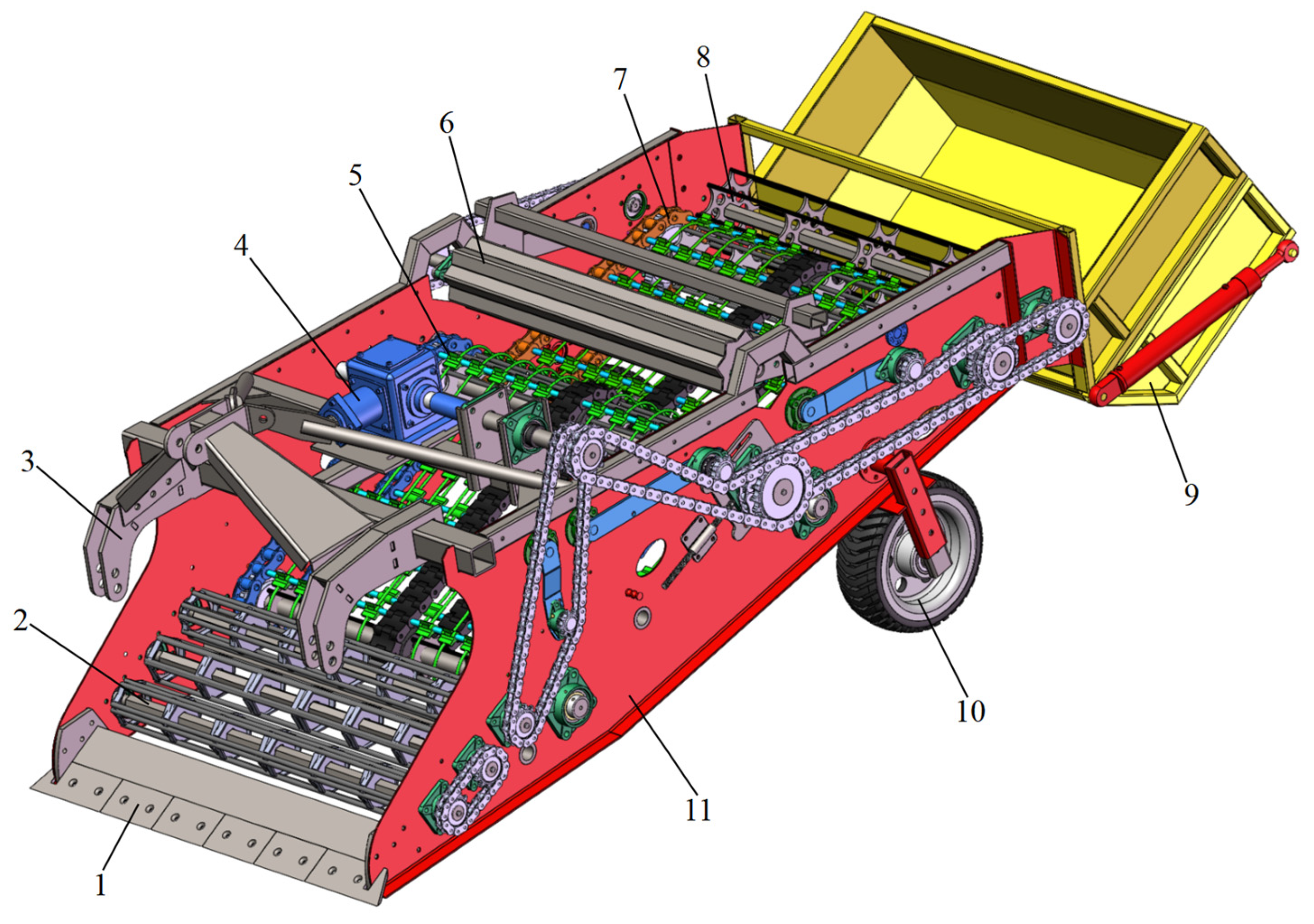
2.1. General Structure and Main Technical Parameters
2.2. Working Principle
3. Key Component Design
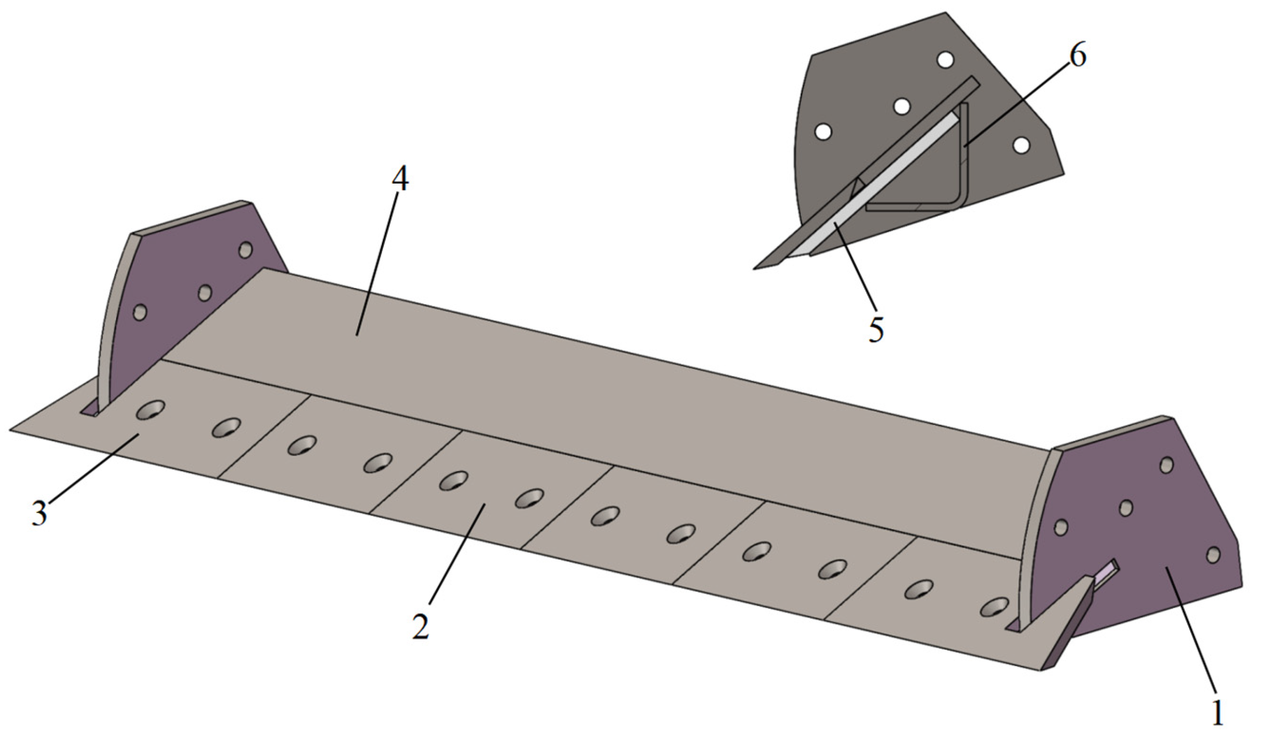
3.1. Excavating Shovel Structural Design
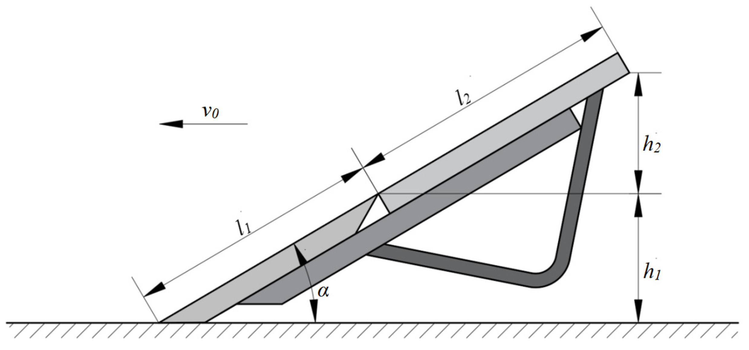
Determination of the Main Parameters of the Excavating Shovel
- Inclination of shovel surface (angle of entry) α;
- 2.
- Length of shovel surface
- 3.
- Excavating shovel width B.
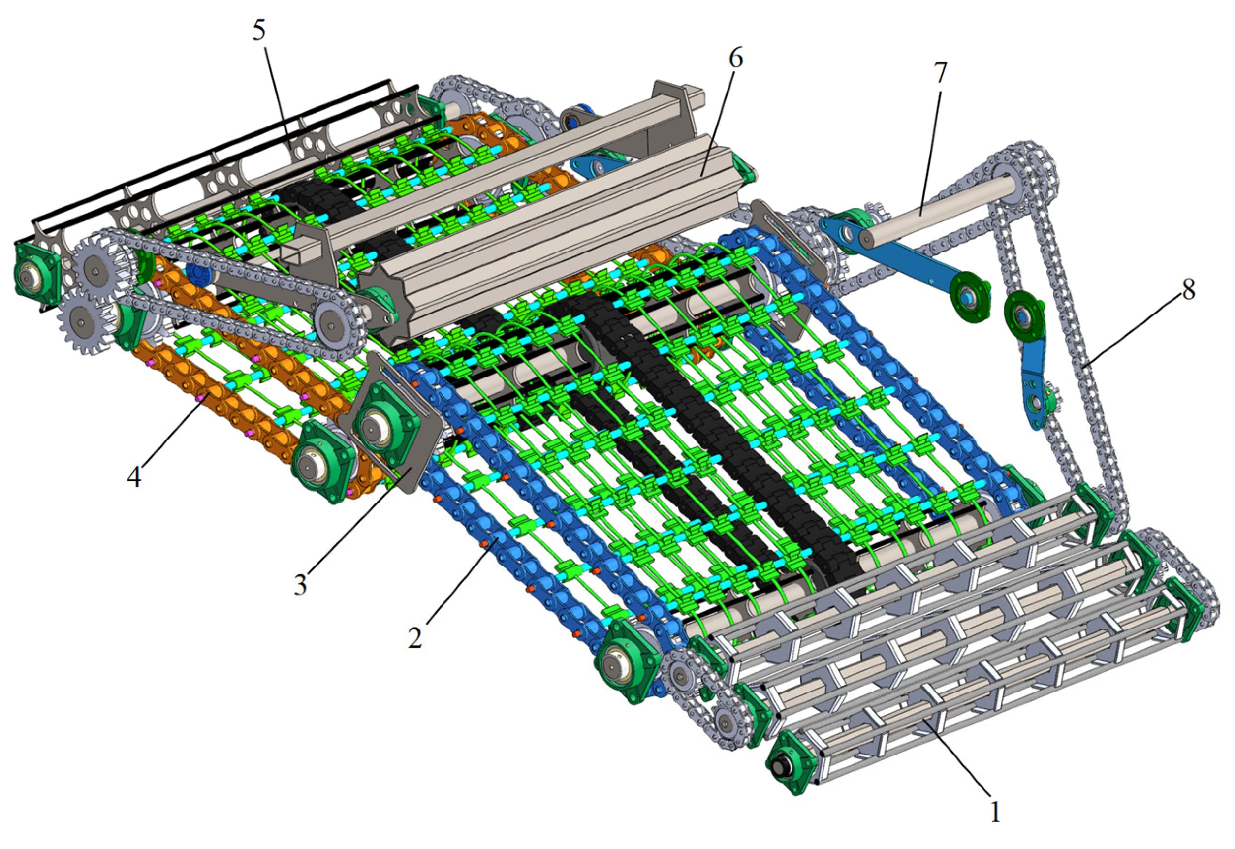
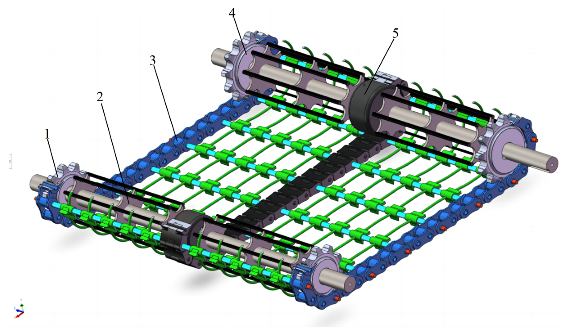
3.2. Structural Design of Conveying and Separating Units
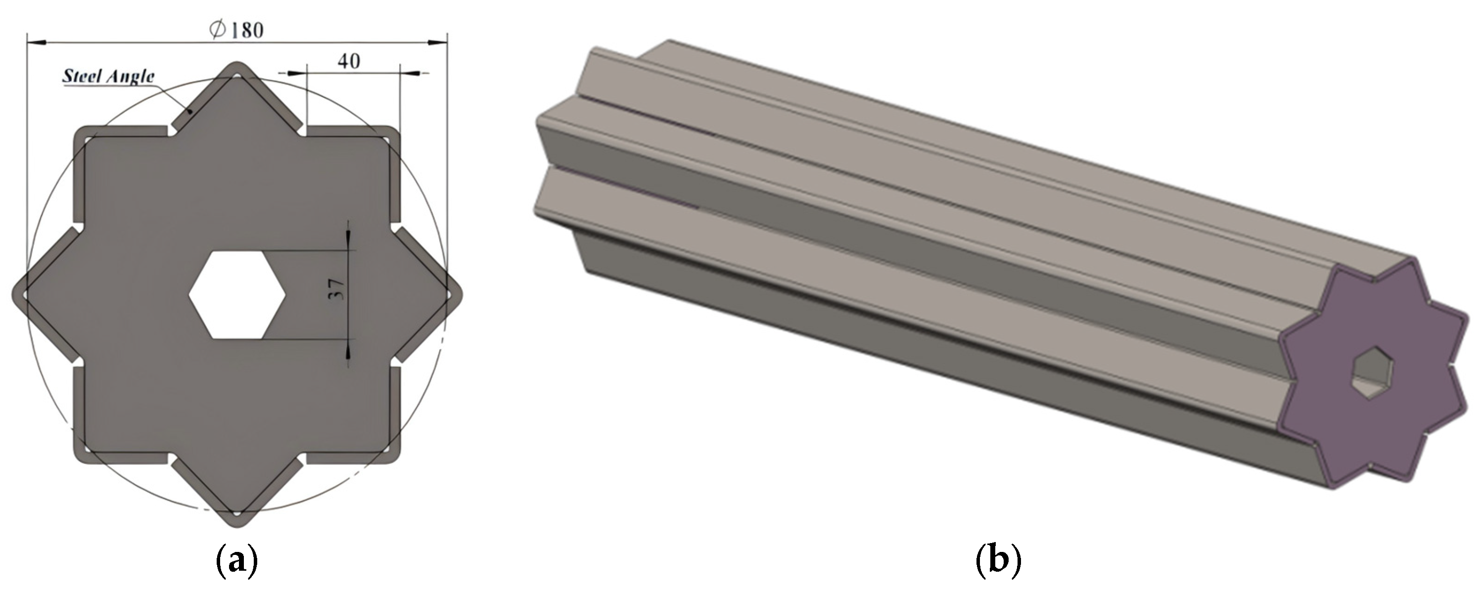
3.2.1. Design of Roller Screen Structure
- Structural design
- 2.
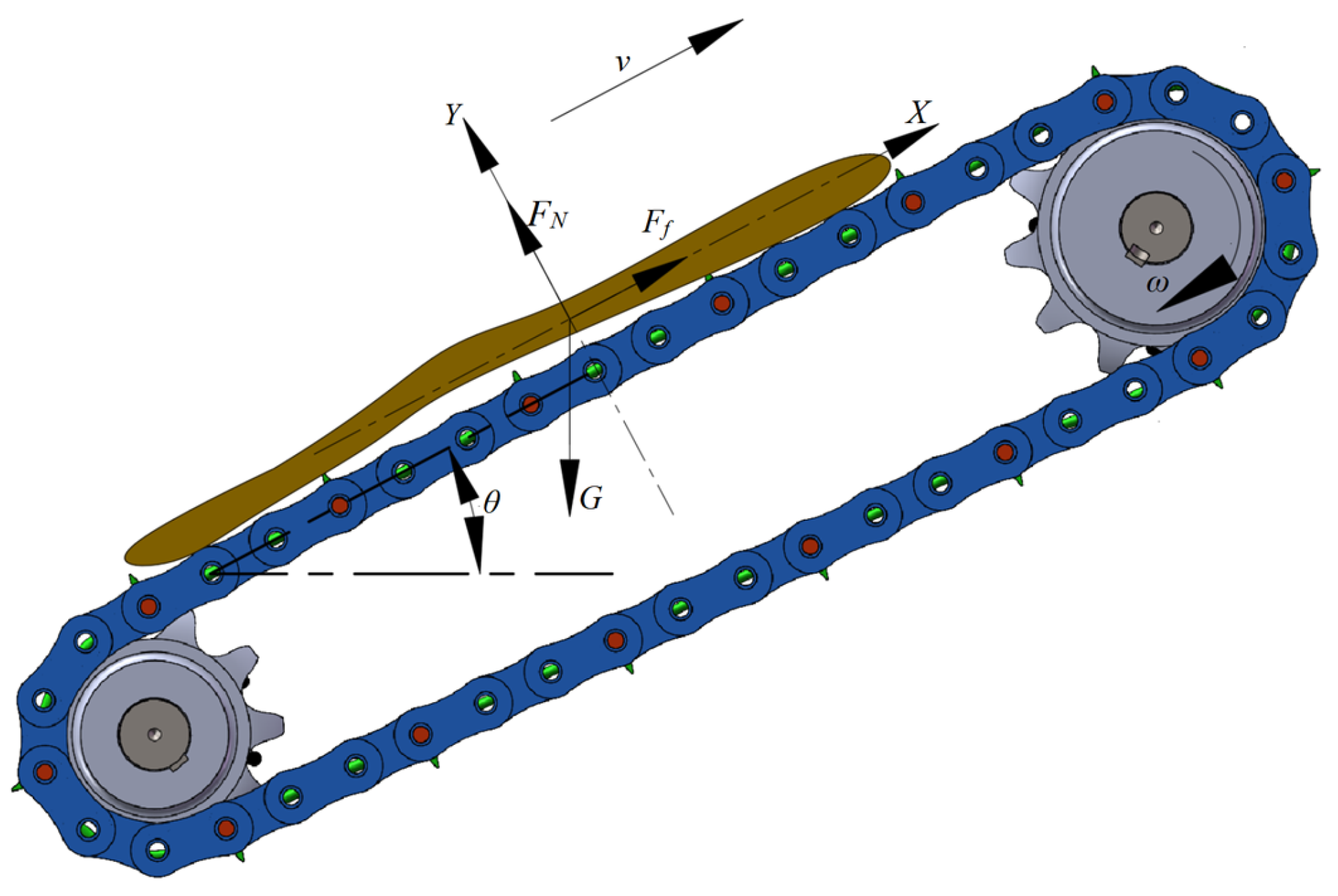
- Force analysis of the roller screen
3.2.2. Design of Sieve Screen
- Force of the soil–pharmaceutical mixture on the sieve screen
- 2.
- Structural design of lift chain conveyor separation screens
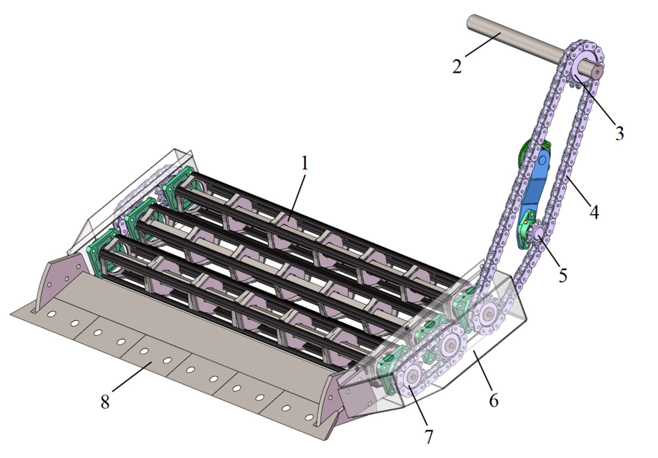
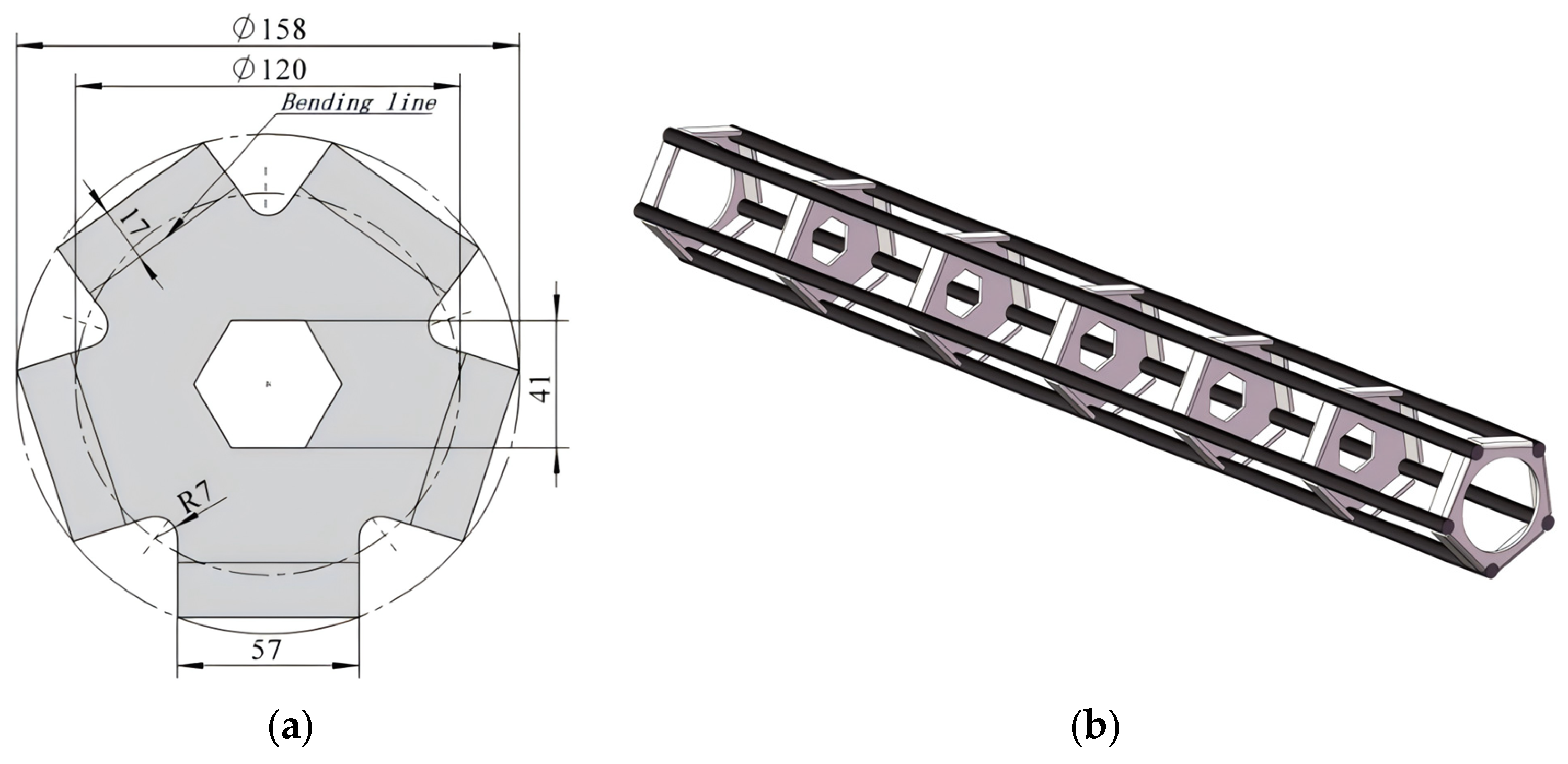
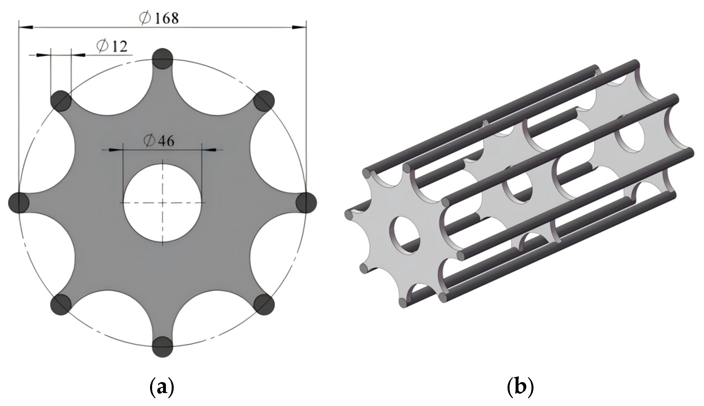
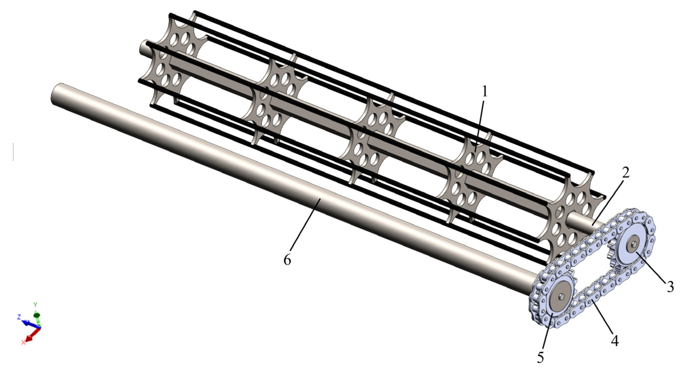
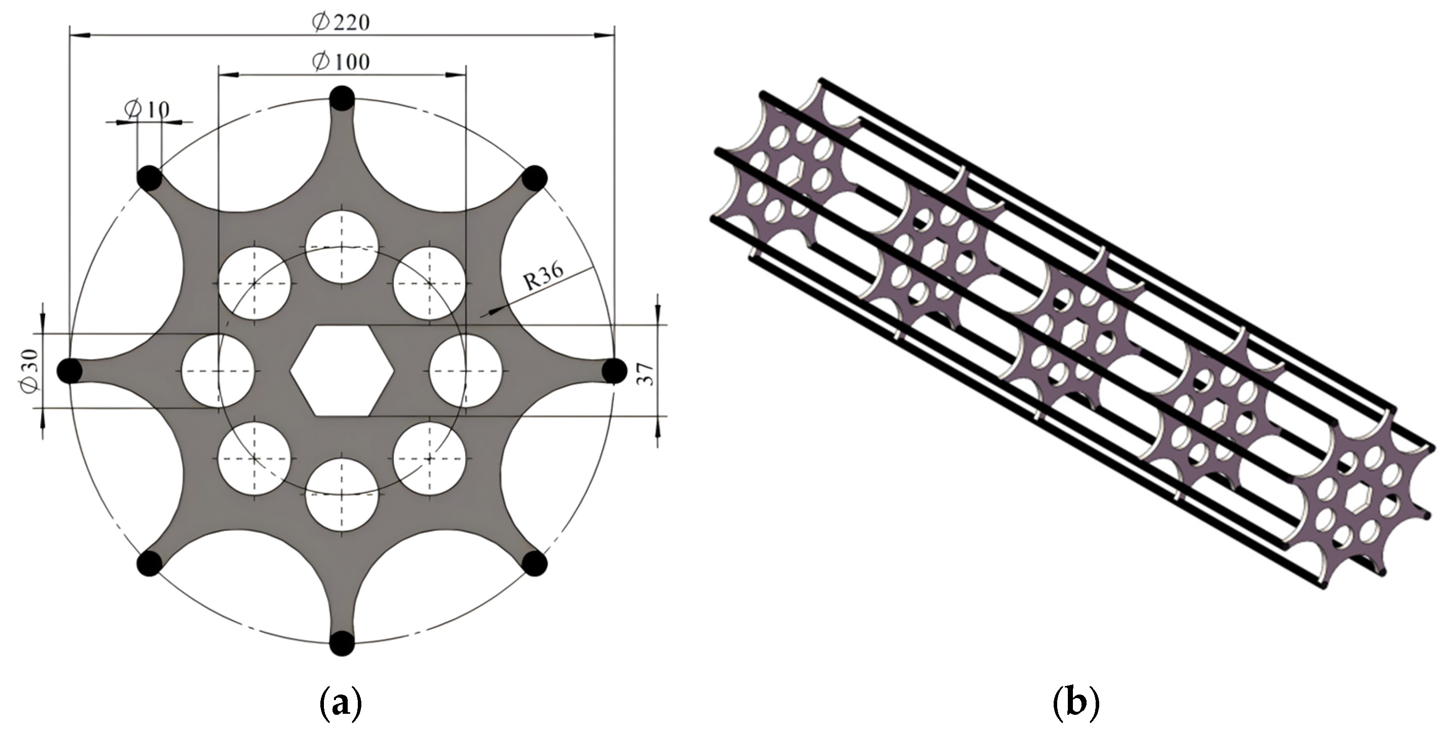
3.2.3. Design of Soil-Crushing Rollers
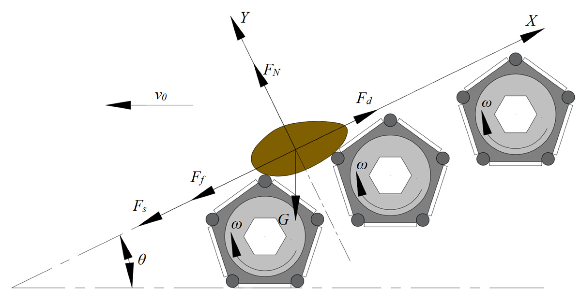
- Force analysis of soil-crushing rollers
- 2.
- Soil-crushing rollers’ structural design
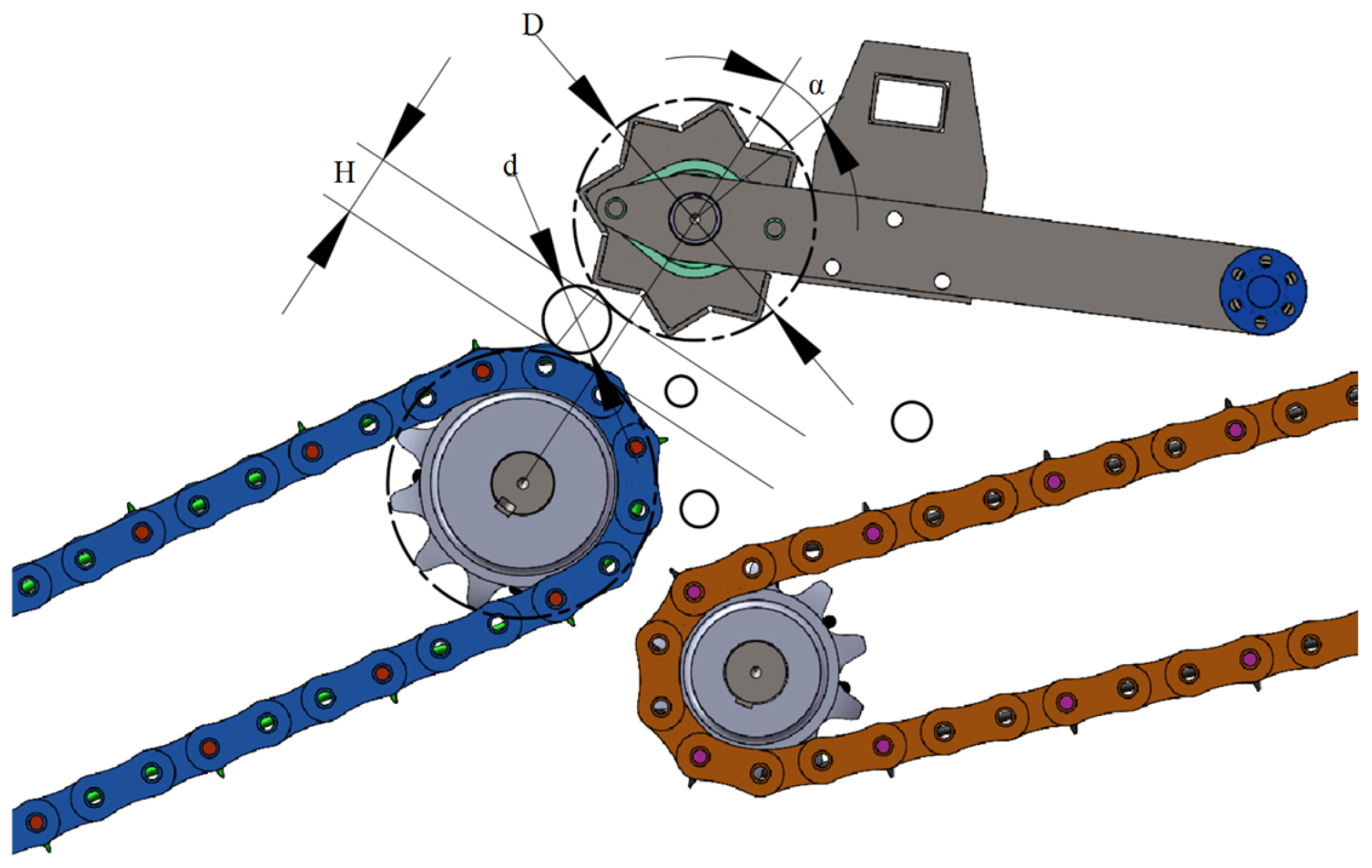
3.2.4. Structural Design of Rear Support Wheel
- a.
- Screen-Conveying Stage: When the top of the licorice begins to leave the screen, its center of gravity remains on the screen, and it continues to move upwards with the screen;
- b.
- Tilting and Touching the Wheel Stage: Once the center of gravity of the licorice leaves the plane of the screen, its head starts to fall. At this stage, the licorice contacts the rotating rear paddle wheel, which supports the tilting and falling licorice and lifts it upward through the rotation of the paddle wheel;
- c.
- Paddle Wheel Support Stage: As the rear paddle wheel rotates, it fully supports the licorice;
- d.
- Leaving the Wheel and Entering the Box Stage: The licorice exits the paddle wheel and falls into the collection box. Meanwhile, soil blocks, which are subject to an oblique throwing movement upon leaving the screen, will fall through the gaps between the crossbars of the paddle wheel and land on the ground.
- Analysis of soil oblique throwing motion
- 2.
- Rear support wheel structure design
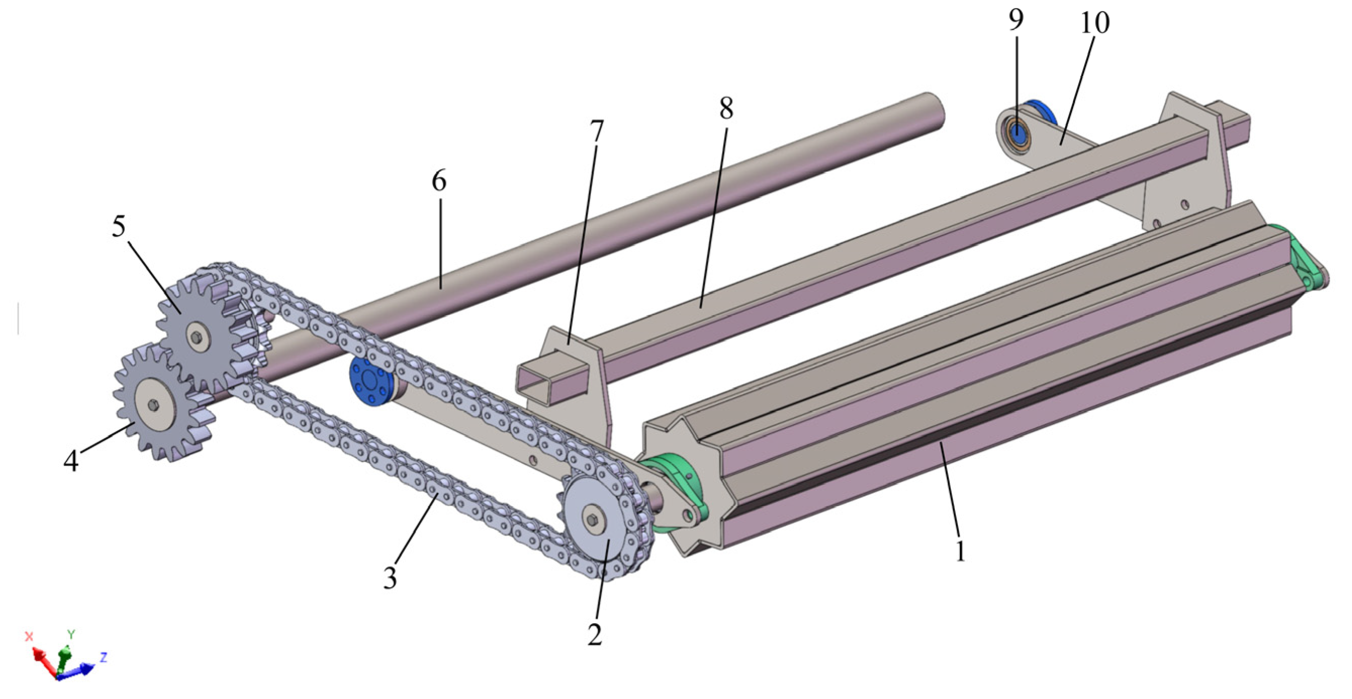
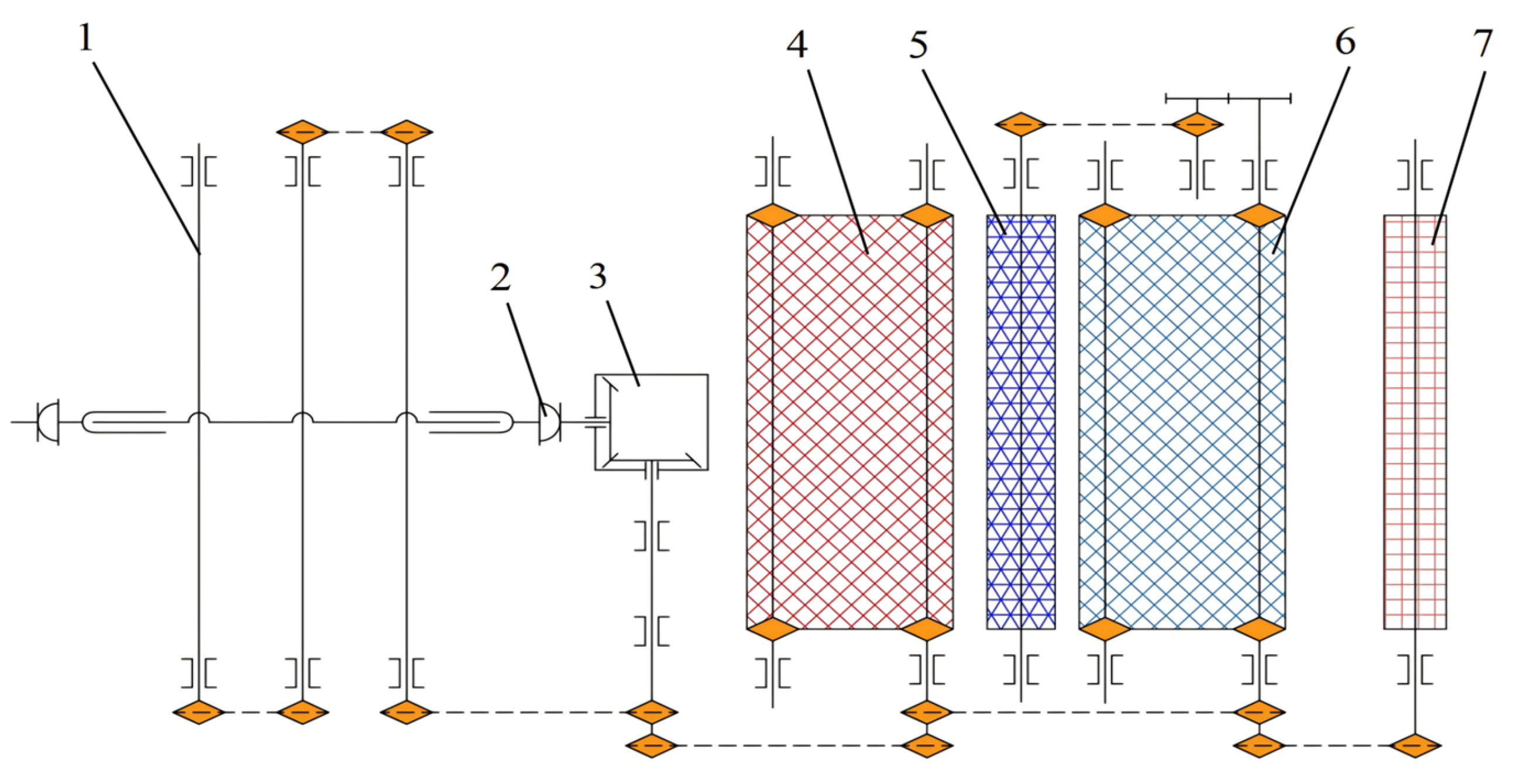
3.3. Structural Design of Power Transmission Part
4. Results
4.1. EDEM Modelling
4.1.1. Contact Model Selection and Parameterization
4.1.2. Modeling of Licorice Soils
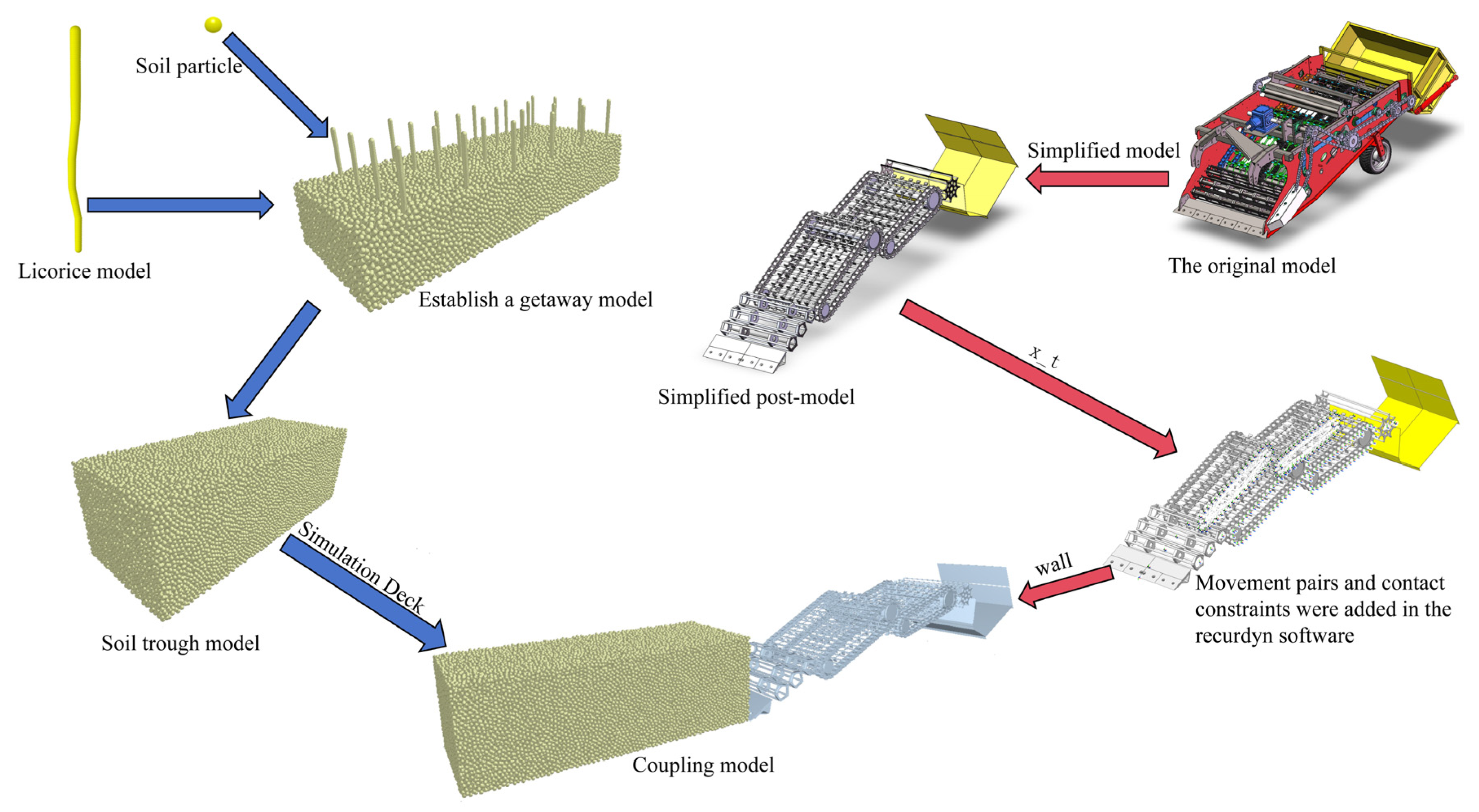
4.2. Coupling Modeling
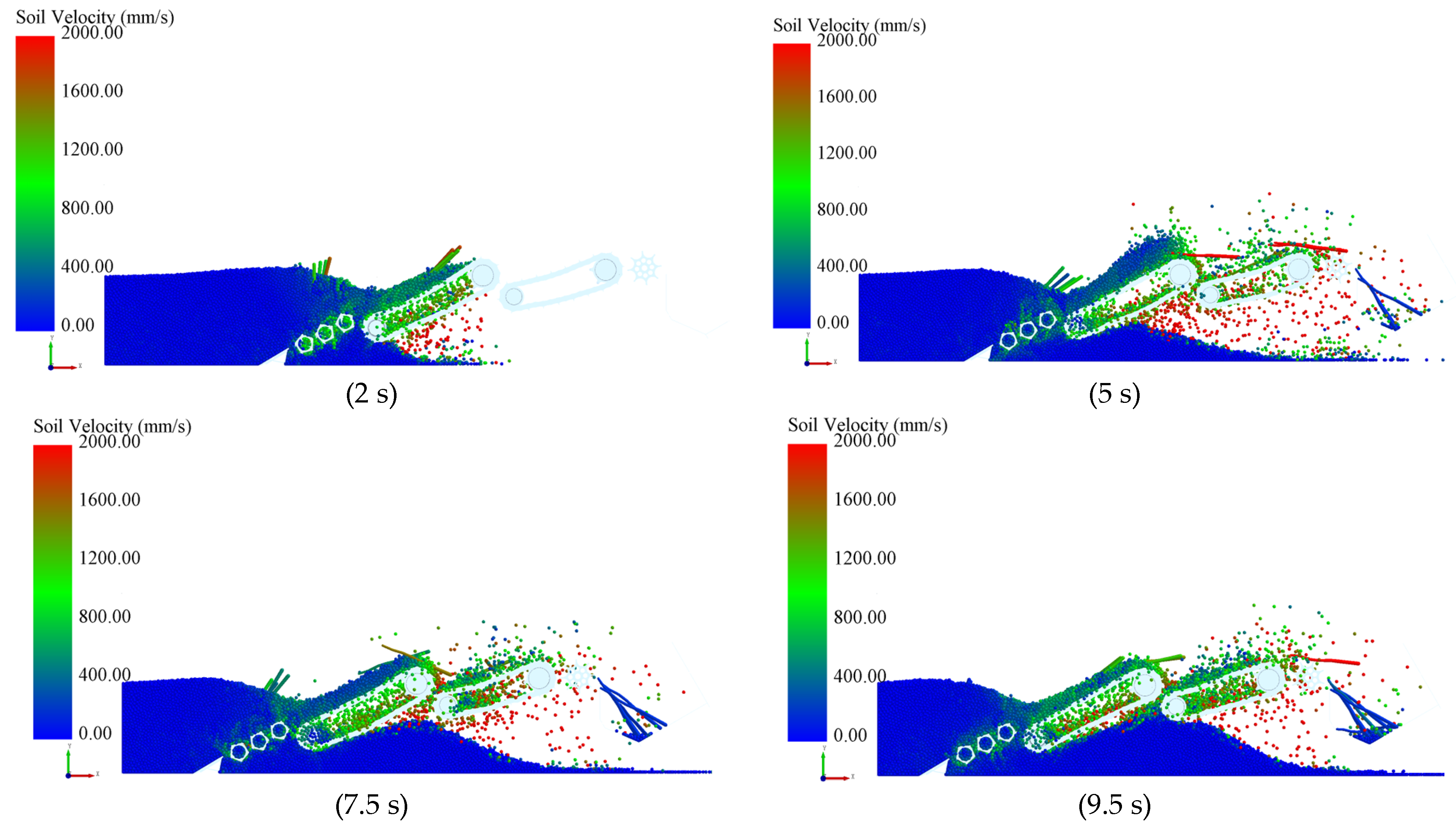
4.3. Simulation Results and Analysis
4.4. Determination of Optimum Working Parameters
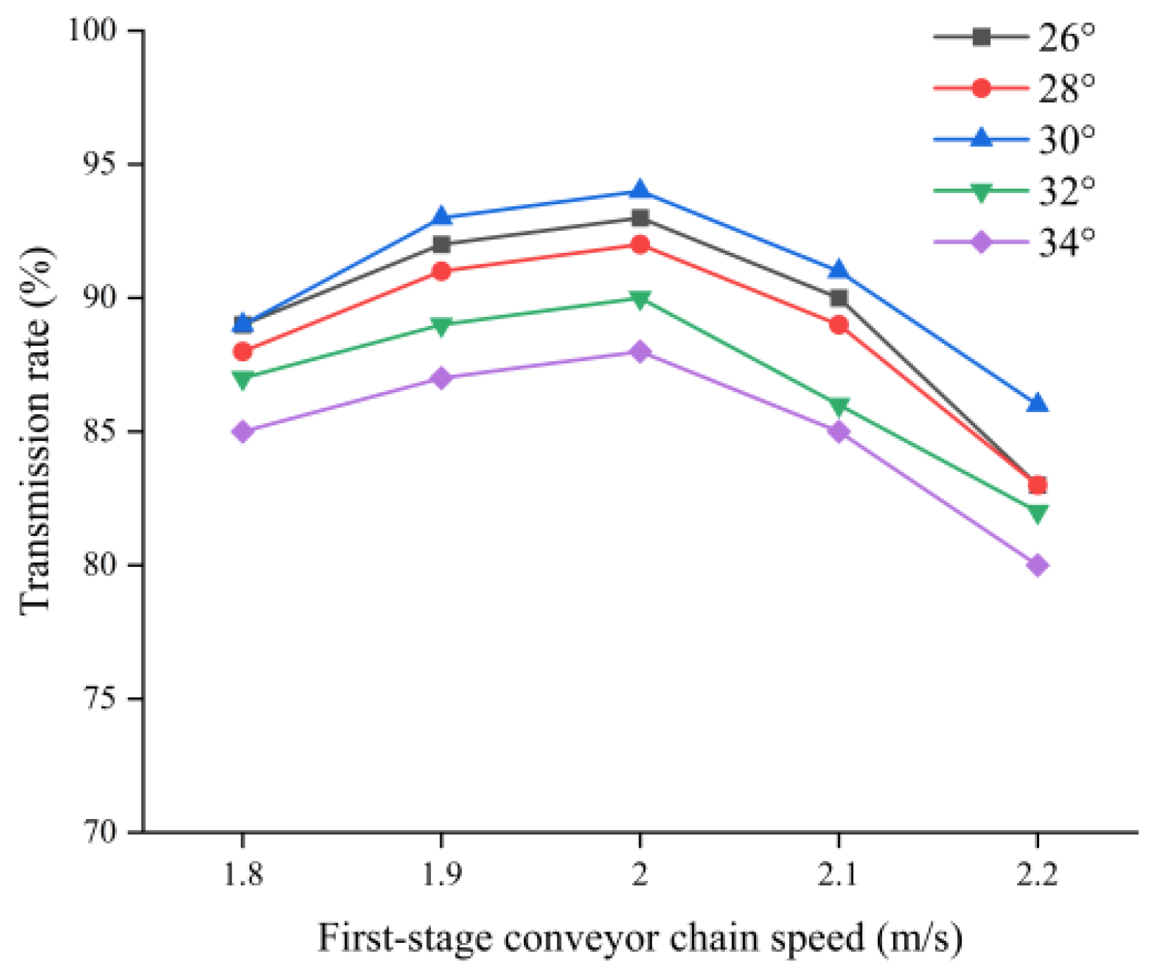
4.4.1. The Effect of First-Stage Conveyor Chain Speed and Unit Operating Angle on the Overall Conveyor Rate
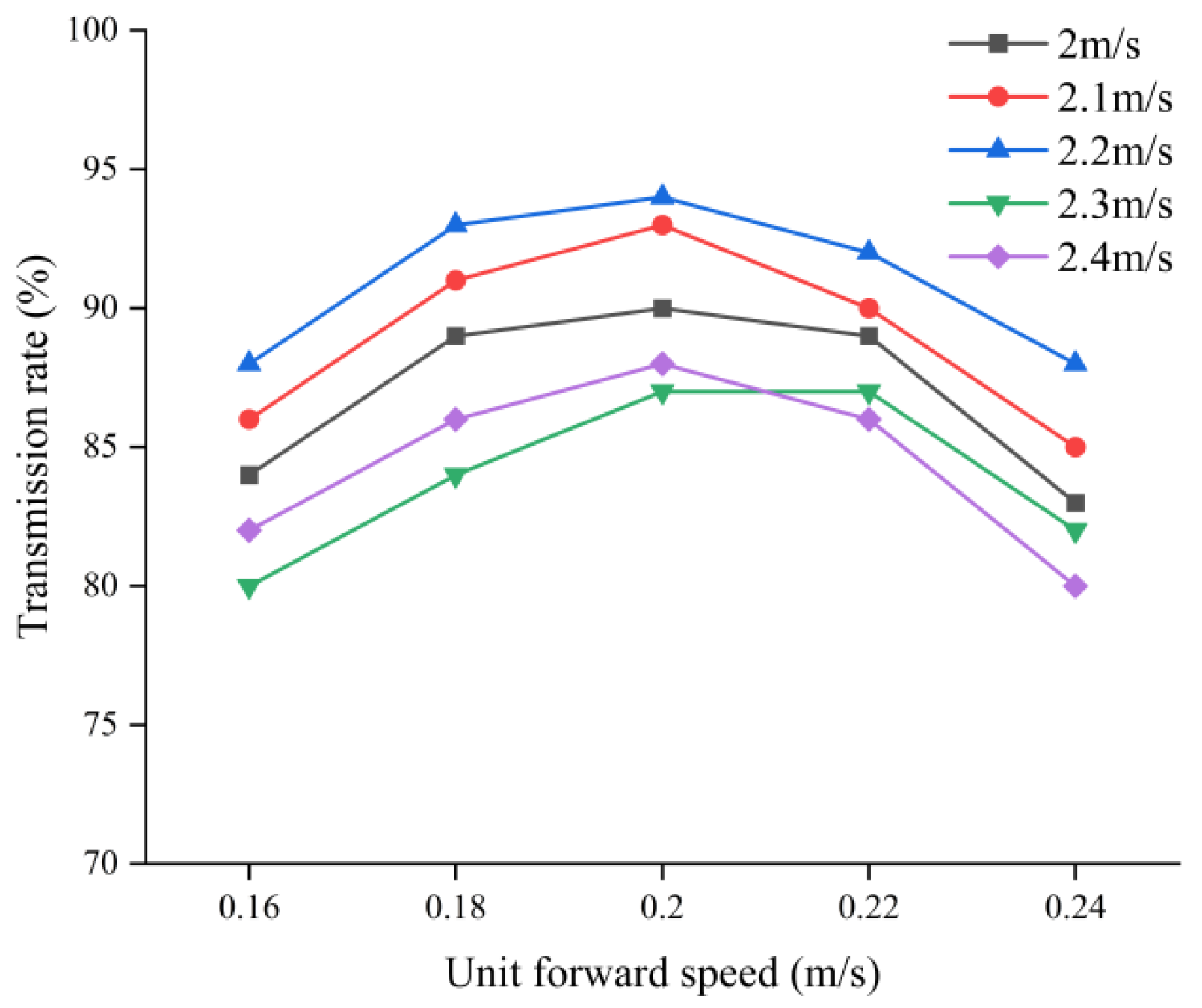
4.4.2. The Effect of Unit’s Forward Speed and Second-Stage Conveyor Chain Speed on the Overall Conveyor Rate
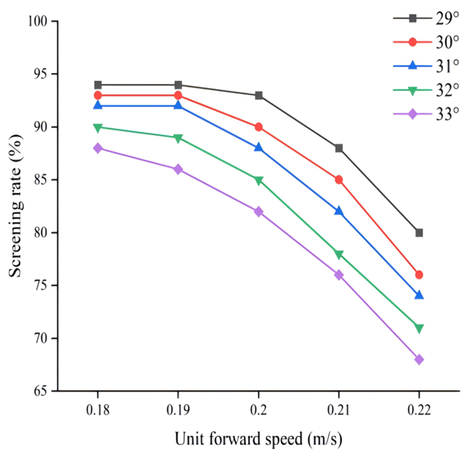
4.4.3. The Effect of the Forward Speed of the Unit and the Speed of the Second-Stage Conveyor Chain on the Overall Screening Rate
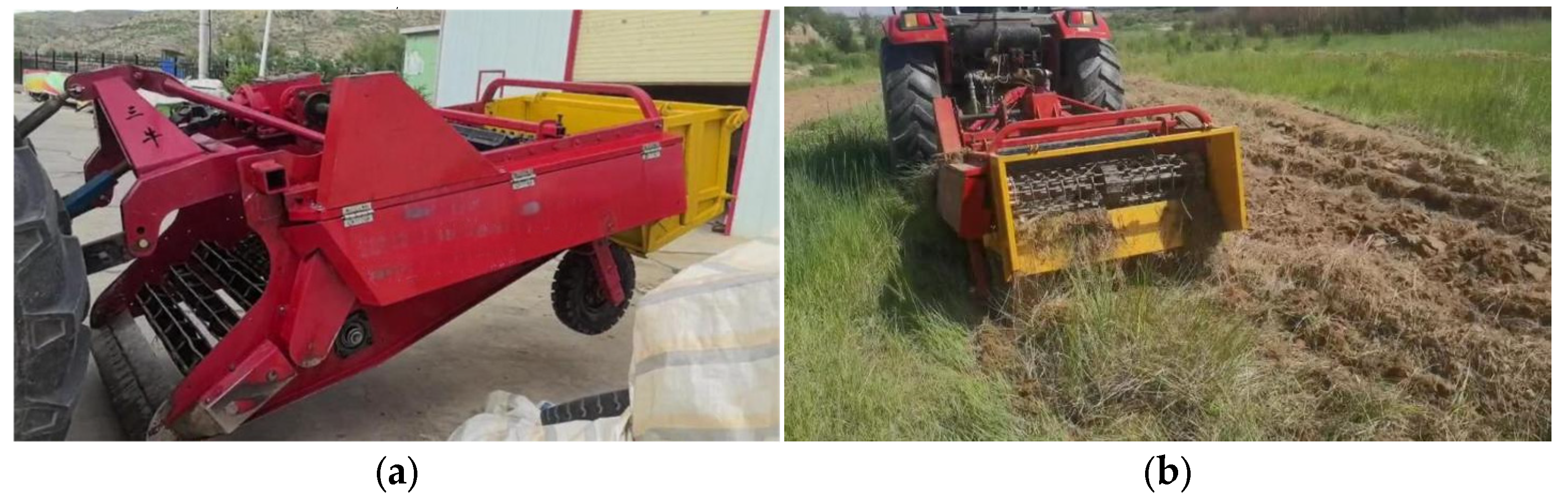
4.5. Field Experiment
5. Conclusions
- (1)
- According to the agronomic requirements of licorice harvesting, a licorice harvester was designed, which can complete the operations of digging, conveying, separating and collecting at one time. The harvesting efficiency of the whole machine is 0.26–0.48 hm/s2, which is four–five times higher than that of the same amount of manual labor. The whole machine is easy to operate and runs smoothly. Compared with traditional manual digging and harvesting, it can reduce the labor intensity of manual labor, reduce the damage to Chinese herbs, improve production efficiency, and is of great significance to increasing the economic benefits for farmers.
- (2)
- After analyzing and designing the structure of the excavating shovel and the conveying separating device, the excavating shovel adopted a plane combination shovel. Three sets of roller screens were used to convey the shoveled soil–medicine mixture to the conveying and separating device, and the optimal rotational speed of the roller screens was 150 rpm. The two-stage conveying and separating screens were of the lifting-chain-type conveying and separating structure. Through theoretical analysis, it is concluded that the screen crossbar spacing is 153 mm, the diameter is 10 mm, the spacing of the finger-like rubber chain is 85 mm, and the crushing-roller diameter is 200 mm, which has the best crushing effect on the soil that has not passed through the first stage of the screen.
- (3)
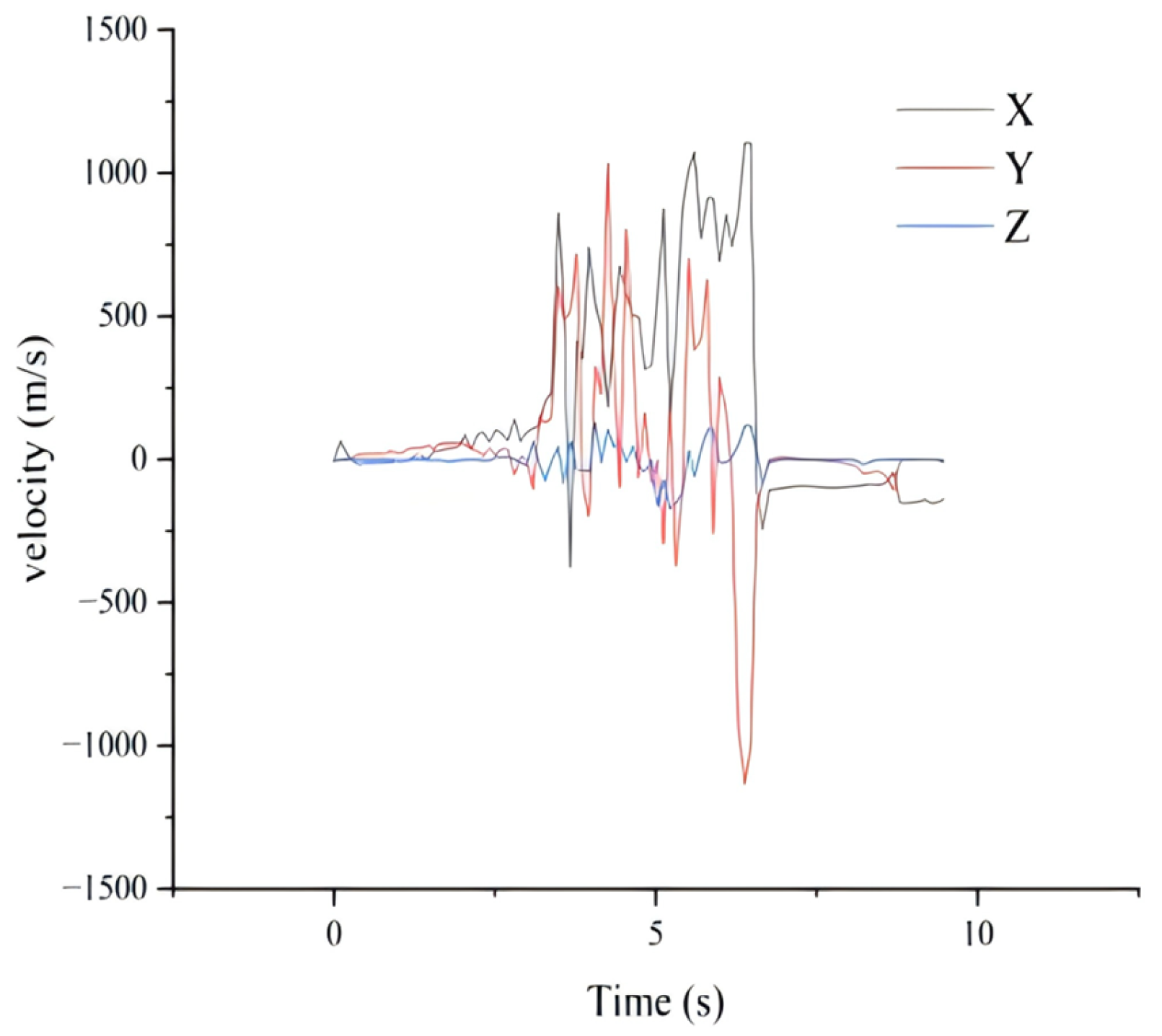
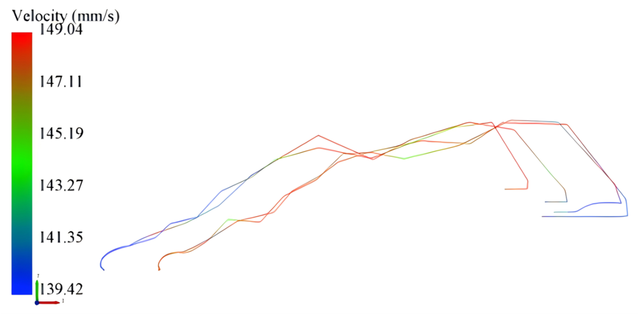
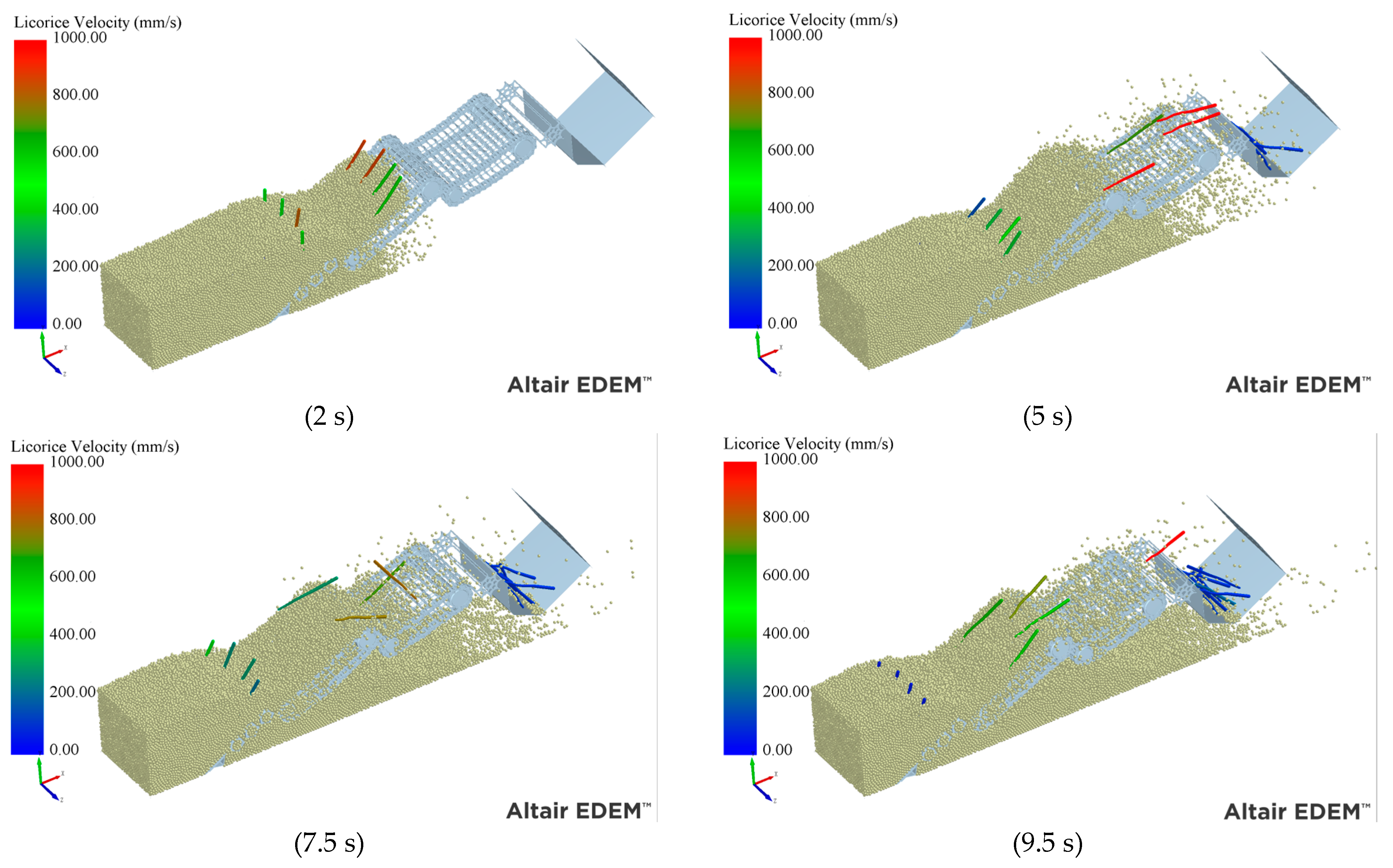
- The harvesting process of the harvester was simulated using EDEM 2022.3 and RecurDyn 2023. The simulation results demonstrated that the conveying and separating screen operated smoothly throughout the process, effectively handling the medicine–soil mixture. The separation was efficient, with the simulation showing complete separation of soil and licorice. During the simulation, the maximum horizontal displacement of the licorice was 2098 mm, and the maximum vertical displacement was 660 mm. The process caused minimal damage to the licorice rhizome, and the licorice was effectively collected into the collection box.
- (4)
- The field test shows that after the operation of the licorice harvester, the net digging rate of licorice is 96.2%, the injury rate is 4.3%, the average digging depth is 580 mm, and the machine operates smoothly during the operation period, which meets the harvesting requirements of mechanization of harvesting of root and stem Chinese herbal medicines. The test indicators have reached the national industry standards.
Author Contributions
Funding
Institutional Review Board Statement
Data Availability Statement
Conflicts of Interest
References
- Cui, X.; Lou, L.; Zhang, Y.; Yan, B. Study of the distribution of Glycyrrhiza uralensis production areas as well as the factors affecting yield and quality. Sci. Rep. 2023, 13, 5160. [Google Scholar] [CrossRef] [PubMed]
- Hayashi, H.; Sudo, H. Economic importance of licorice. Plant Biotechnol. 2009, 26, 101–104. [Google Scholar] [CrossRef]
- Zhang, C.; Song, J.; Dong, X.; Wang, J.; Yu, Y.; Xu, G.; Wang, C.; Liu, W.; Zhu, B. Status quo and prospects of licorice mechanized harvesting technology in China. In Proceedings of the 2019 ASABE Annual International Meeting, Boston, MA, USA, 7–10 July 2019; American Society of Agricultural and Biological Engineers: St. Joseph, MI, USA, 2019; p. 1. [Google Scholar]
- Chen, L.; Zhang, Y.; Wang, D. Research on mechanized harvesting technology and equipment for root and tuber Chinese herbal medicine in hilly area. Hebei Agric. Mach. 2021, 281, 1–2. [Google Scholar]
- Zhou, J.; Feng, X.; Liu, H.; Li, J. Development Status and Strategies of Glycyrrhiza uralensis Planting Industry. J. Anhui Agri. Sci. 2012, 40, 10065–10066. [Google Scholar] [CrossRef]
- Li, K. Research on Key Technologies of Self-Propelled Carrot Combine Harvester; China Academy of Agricultural Mechanization Sciences: Beijing, China, 2015. [Google Scholar]
- Rao, G.; Chaudhary, H. A review on effect of vibration in tillage application. IOP Conf. Ser. Mater. Sci. Eng. 2018, 377, 012030. [Google Scholar] [CrossRef]
- Yu, Q.; Zhang, L.; Cai, Z.; Liu, Y.; Gong, Y.; Cao, G. Present status and prospect of mechanized production of Rhizome Chinese herbal medicine in Gansu Province. J. Chin. Agric. Mech. 2023, 44, 29–36. [Google Scholar] [CrossRef]
- Xie, X. Design and Experimental Study on Licorice Harvester. Ph.D. Thesis, Xinjiang Agricultural University, Ürümqi, China, 2015. [Google Scholar]
- Sheng, G.; He, C.; Wang, H.; Jia, D. Development of 4WGX-120/150-type root herb excavator. Agric. Mach. 2012, 112–114. [Google Scholar] [CrossRef]
- Zhang, S.; Xiong, W.; Zhu, D.; Yu, S.; Wang, X. Design on rhizome Chinese herbal medicine harvesting machinery. J. Chin. Agric. Mech. 2016, 37, 27–33. [Google Scholar]
- China Academy of Agricultural Mechanization Science. Agricultural Machinery Design Manual; Agricultural Science and Technology Press: Beijing, China, 2007. [Google Scholar]
- Li, B. Agricultural Mechanics; Agricultural Press: Beijing, China, 2003. [Google Scholar]
- Wang, X.; Song, J.; Liu, C.; Dong, X.; Wang, J.; Zhang, C. Design and experiment on licorice tilt transplanting furrow opener. Trans. Chin. Soc. Agric. Eng. 2016, 32, 16–23. [Google Scholar]
- Li, X.; Shang, S.; Chen, M.; Lang, X.; Yao, W.; Li, W. Mechanical Damage of Multistage Conveying Device of Potato Harvester. J. Agric. Mech. Res. 2024, 1–8. [Google Scholar] [CrossRef]
- Zhang, Z. Design and Simulation of Propelled Potato Combined Harvester in Hilly Country. Ph.D. Thesis, Kunming University of Science and Technology, Kunming, China, 2022. [Google Scholar]
- Du, J.; Sun, W.; Zhao, M.; Wang, J.; Simionescu, P.A. Design and Experimental Results Obtained with an Astragalus Digger Prototype. Agriculture 2024, 14, 701. [Google Scholar] [CrossRef]
- Jiao, Y.; Gong, Z.; Li, X. Design and test of excavator separating device for long root chinese medicinal materials. Xinjiang Agric. Mech. 2023, 12–15. [Google Scholar] [CrossRef]
- Wang, F.; Wen, B.; Xie, X.; Xie, K.; Guo, S.; Zhang, Z. Operation Mechanism Analysis and Parameter Optimization of Conveying and Separating Device of Panax notoginseng Harvester. Trans. Chin. Soc. Agric. Mach. 2023, 54, 201–211+259. [Google Scholar]
- Zheng, Z.; Cui, B.; Gao, W.; Wei, Y.; Wu, M.; Li, A. Design and field test of a special Chinese herbal medicine harvester. Int. J. Agric. Biol. Eng. 2022, 15, 109–115. [Google Scholar] [CrossRef]
- Kang, H.; Liu, M.; Wang, L.; Wei, M.; Liu, J.; Zhou, J.; Zhang, S. Simulation Analysis of Separating and Conveying Device of Potato Harvester Based on EDEM. J. Agric. Mech. Res. 2022, 44, 1–8+16. [Google Scholar]
- Shi, L.; Zhao, W.; Sun, W. Parameter calibration of soil particles contact model of farmland soil in northwest arid region based on discrete element method. Trans. Chin. Soc. Agric. Eng. 2017, 33, 181–187. [Google Scholar]
- Li, Y.; Hu, Z.; Gu, F.; Wang, B.; Fan, J.; Yang, H.; Wu, F. DEM-MBD Coupling Simulation and Analysis of the Working Process of Soil and Tuber Separation of a Potato Combine Harvester. Agronomy 2022, 12, 1734. [Google Scholar] [CrossRef]
- Wan, L.; Li, Y.; Liu, Z.; Song, J.; Dong, X.; Song, J. Study on behavior rules of the licorice-soil-licorice oscillating harvester coupled system using numerical method. Comput. Electron. Agric. 2024, 226, 109479. [Google Scholar] [CrossRef]
- Ministry of Agriculture and Rural Affairs of the People’s Republic of China. Rhizome Chinese Medicinal Materials Harvesters: Technical Specification of Quality Evaluation; China Agriculture Press: Beijing, China, 2019. [Google Scholar]
- Ministry of Agriculture and Rural Affairs of the People’s Republic of China. Medicinal Excavator; China Agriculture Press: Beijing, China, 2019. [Google Scholar]


| Parameters | Numerical Value |
|---|---|
| Overall size (Length × Width × Height) | 3450 × 1830 × 1410 (mm) |
| Motive force | 65 kw |
| Working width | 1200 mm |
| Digging depth | 500–600 mm |
| Materials | Poisson’s Ratio | Shear Modulus/pa | Densities (kg/m3) |
|---|---|---|---|
| soil | 0.3 | 5 × 10⁷ | 2600 |
| licorice | 0.416 | 1.668 × 10⁷ | 840 |
| steel | 0.3 | 7.9 × 10¹⁰ | 7860 |
| Contact Type | Coefficient of Static Friction | Coefficient of Rolling Friction | Coefficient of Restitution |
|---|---|---|---|
| Soil–soil | 0.68 | 0.27 | 0.21 |
| Soil–licorice | 0.453 | 0.17 | 0.587 |
| Soil–steel | 0.31 | 0.13 | 0.54 |
| Licorice–licorice | 0.453 | 0.086 | 0.587 |
| Licorice–steel | 0.349 | 0.074 | 0.509 |
| Determination Index | Technical Index | Measured Mean Value |
|---|---|---|
| Excavation rate/% | ≥95 | 96.2 |
| Wound rate/% | ≤5 | 4.3 |
| Digging depth/mm | ≥500 | 580 |
Disclaimer/Publisher’s Note: The statements, opinions and data contained in all publications are solely those of the individual author(s) and contributor(s) and not of MDPI and/or the editor(s). MDPI and/or the editor(s) disclaim responsibility for any injury to people or property resulting from any ideas, methods, instructions or products referred to in the content. |
© 2024 by the authors. Licensee MDPI, Basel, Switzerland. This article is an open access article distributed under the terms and conditions of the Creative Commons Attribution (CC BY) license (https://creativecommons.org/licenses/by/4.0/).
Share and Cite
Lu, Y.; Sun, W.; Yang, X.; Zhao, M.; Simionescu, P.A. Analytical Design and Test of Licorice Harvester Based on DEM–MBD Coupling. Agronomy 2024, 14, 2651. https://doi.org/10.3390/agronomy14112651
Lu Y, Sun W, Yang X, Zhao M, Simionescu PA. Analytical Design and Test of Licorice Harvester Based on DEM–MBD Coupling. Agronomy. 2024; 14(11):2651. https://doi.org/10.3390/agronomy14112651
Chicago/Turabian StyleLu, Yonggang, Wei Sun, Xiaoping Yang, Ming Zhao, and Petru A. Simionescu. 2024. "Analytical Design and Test of Licorice Harvester Based on DEM–MBD Coupling" Agronomy 14, no. 11: 2651. https://doi.org/10.3390/agronomy14112651
APA StyleLu, Y., Sun, W., Yang, X., Zhao, M., & Simionescu, P. A. (2024). Analytical Design and Test of Licorice Harvester Based on DEM–MBD Coupling. Agronomy, 14(11), 2651. https://doi.org/10.3390/agronomy14112651