Article

Discrete Element Method–Multibody Dynamics Coupling Simulation and Experiment of Rotary Tillage and Ridging Process for Chili Pepper Cultivation

College of Mechanical and Electrical Engineering, Gansu Agricultural University, Lanzhou 730070, China
*
Author to whom correspondence should be addressed.
Agronomy 2024, 14(3), 446; https://doi.org/10.3390/agronomy14030446
Submission received: 2 February 2024 / Revised: 21 February 2024 / Accepted: 22 February 2024 / Published: 24 February 2024
(This article belongs to the Section Precision and Digital Agriculture)

Abstract

:
Rotary tillage, ridging, and mulching are commonly used cultivation methods for crops such as chili peppers, tomatoes, and strawberries in the arid regions of Northwest China. An integrated machine for rotary tillage, ridging, and mulching was designed by considering the growth characteristics of pepper root systems and the agronomic requirements of ridge beds. The structural parameters and their value ranges for key components such as the rotary tillage device and the ridging device were determined. By introducing the Bonding contact parameter, the soil cohesion between soil particles during the process of rotary tillage and ridging can be simulated. A coupled simulation model using the Discrete Element Method (DEM) and Multibody Dynamics (MBD) is established. The experimental factors selected were rotary tillage depth, ridging roller speed, and machine forward speed. The evaluation indexes were the traction resistance of the stemming roller and the soil compactness of the ridges. A response surface Box–Behnken Design test was carried out to obtain the best working parameters of the rotary tillage and ridging process for chili pepper cultivation as follows: the rotary tillage depth was 176 mm, the ridging roller speed was 283.71 r/min, and the machine forward speed was 0.55 m/s. Field experiments with optimal parameters showed that the ridge top width was 549.2 mm, the ridge bottom width was 750.5 mm, the ridge height was 222.9 mm, the ridge spacing was 1173.1 mm, the surface smoothness of the ridge was 12.3 mm, the width of soil covering the film edge was 76.3 mm, the stability coefficients of the ridge size parameters were all above 91.73%, and the soil compactness after operation was 60.82 KPa. All indicators meet the requirements for the rotary tillage and ridging cultivation of chili peppers in arid regions, providing reference for the design of rotary tillage and ridging mulching implements and the development of sustainable agriculture.

1. Introduction

Chili pepper, belonging to the Capsicum genus in the Solanaceae family, is a major crop in China, contributing to around one-third of the world’s total production value. China is the largest producer and exporter of chili peppers [1]. In the cultivation process of chili peppers, rotary tillage, ridging, and mulching have a significant impact on promoting crop growth and development, maintaining temperature and moisture, and improving soil and crop transparency and air permeability. They are important methods for increasing yield [2]. However, manual ridging for chili pepper cultivation currently faces challenges such as low ridging height, low efficiency, and easy collapse of ridges [3].
There are three main types of ridge-making machinery: disc plough ridge machinery, plowshare-type ridge machinery, and rotary tillage ridge machinery, as shown in Table 1, which compares their working principles and advantages and disadvantages. The disc plough ridge machinery is one of the earliest forms of ridge-making machinery. In the early stages of agricultural mechanization, people started using disc plough ridge machinery to cut and flip the soil for ridge-making operations. However, the adjustment process for the disc plough is cumbersome and difficult, and it is not suitable for clayey soil plots [4]. Subsequently, with the advancement and maturity of plowshare-type technology, researchers began to study and use the plowshare type for ridge-making operations. The curved shape and sharp blade of the plowshare type make cutting and flipping the soil easier, resulting in raised ridges. Through continuous improvement and refinement of the plowshare-type ridge machinery, ridge-making operations have become more efficient and precise. The rotary tillage ridge machinery is a relatively newer type of ridge-making machinery [5], where the soil is flipped and mixed by the rotating and cutting actions of the tools and various ridge-forming devices are used to shape the ridges [6]. This significantly improves the quality and efficiency of ridge-making operations.
Numerous studies have been conducted by scholars both domestically and internationally on ridge-forming machines. The Netherlands-based STRUIK company developed a four-row folding ridge-forming machine with a dual rotor design for rotary tillage, capable of digging up to 25 cm deep. It is equipped with a ridge-forming disc assembly to create ridges for crops such as onions, carrots, and endives [10]. The German GRIMME company developed a plowshare-type ridge-forming machine with adjustable plowshares, capable of forming a complete ridge or two half-ridges in each pass [11]. The Italian FORIGO company introduced the STF-110 model ridge-mulching machine, which allows for adjustable ridge width through various mounting holes on the ridge plow frame. It also features an adjustable film tension clutch to improve mulching quality [12]. The Japanese YANMAR company developed the BS142CHN model ridge-forming machine, which integrates top and side shaping plates to form suitable ridges for vegetable transplanting while significantly reducing soil backflow [13]. Domestic scholars Zhang et al. [14] developed a ridge-leveling machine suitable for cold waterlogged paddy fields, based on the technology of mechanical ridging. They optimized key components such as a ridge roller and micro-ridge opener to enhance the stability of ridging operations. Tan [15] developed a combined seeding and ridge-forming machine, improving the performance of ridge-forming operations through field comparative tests with different ridge openers at optimal parameter levels. Zhang et al. [16] proposed a comprehensive cultivation and ridge forming solution for potatoes, incorporating digging, fertilization, planting, and ridge forming. They designed a two-stage combination ridge-forming device for potato planters based on the principle of ridge compression molding. The overall dimensions of the wing shovel, as well as the parameters of the shovel tip, shovel face, and wing plate, were optimized according to the agronomic requirements of potato ridging.
In recent years, DEM-MBD coupled simulation technology has been widely applied in the field of agricultural machinery. Wang et al. [17] developed a side-filling rice precision hole-directed seed measuring device, used DEM-MBD coupled simulation to analyze the seed breakage rate and seeding performance under different rotational speeds, and optimized the seeding performance of the device. Shi et al. [18] improved the design of a vertical cavity seeder based on the DEM-MBD coupling method and investigated the interference and anti-entry characteristics of cavity seeds in soil. Li et al. [19] used DEM-MBD coupled simulation and experimental analysis to optimize the parameters related to the soil and tuber separation process in a potato harvester and validated the effectiveness of the simulation model through field tests and error calculations. Chen et al. [20] developed a sweet potato ridge-forming machine with a plowshare structure and optimized the surface structure parameters of the plowshare through DEM-MBD coupled simulation, effectively reducing the cultivation resistance during machine operation. Therefore, a chili pepper rotary tillage ridge-mulching machine was designed. Through theoretical analysis of the rotary tillage ridge process, the range of influential factors affecting the quality of chili pepper ridges was determined. In addition, DEM-MBD coupled simulation technology and experimental analysis were utilized to obtain the optimal combination of working parameters for these factors. Field experiments were conducted to validate the results, providing reference for the structural form and optimization of working parameters for the chili pepper rotary tillage ridge-mulching machine.

2. Agronomic Requirements and Structural Design

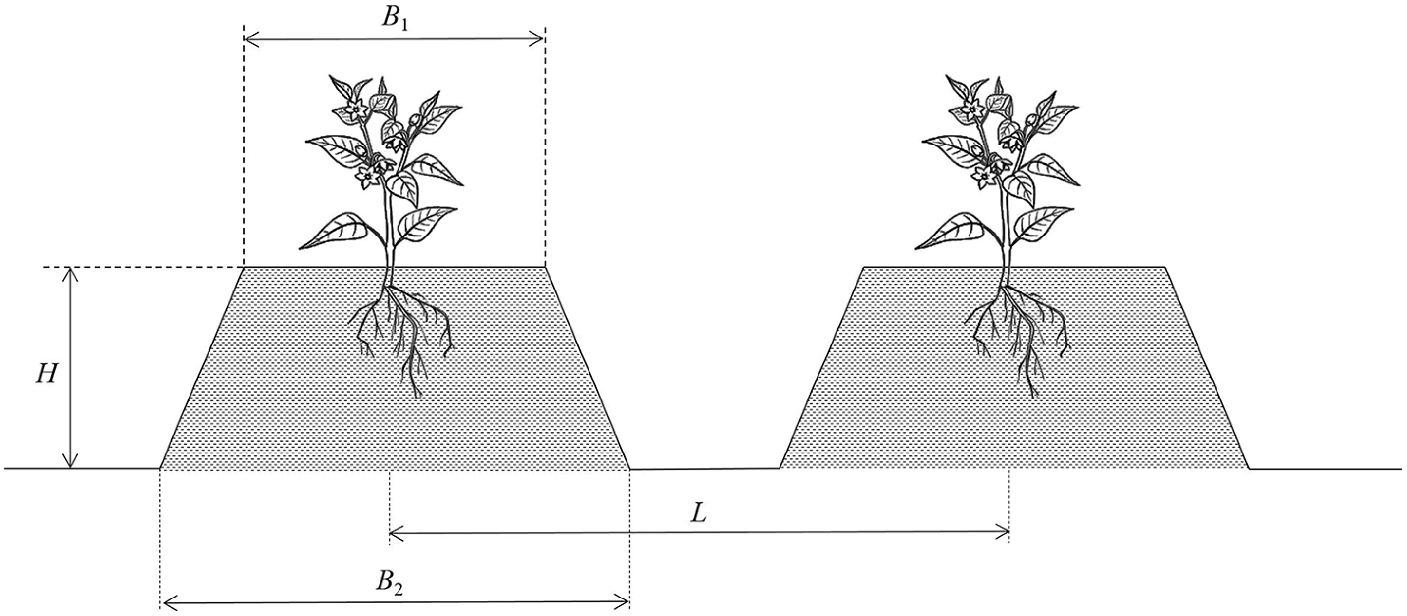
2.1. Agronomic Requirements for Chili Pepper Ridging

In order to obtain the root growth characteristics and appropriate ridge dimensions for chili pepper cultivation in the arid regions of Northwest China, field investigations were conducted in the Jingtai area of Gansu Province. Forty mature ridge-grown chili pepper plants were randomly selected in the field, and ridge cross-sections were excavated along a direction perpendicular to the ridge body. The root profile parameters were measured within the cross-sections, revealing that 70% to 80% of the chili peppers’ roots were distributed within the top 180 mm soil layer, with a dense width ranging from 175 mm to 250 mm. The measurement results are shown in Figure 1.
Due to variations in soil and climatic conditions, the parameters of chili pepper ridges in different regions are often given as a range. In areas with higher rainfall, such as the hilly terrain of the northwest region, where the soil texture is loose and the steep terrain is prone to intense water erosion, it is beneficial to lower the height of the ridges to enhance their solidity. Planting crops on the ridges helps to prevent erosion caused by rainfall and promotes better drainage and ventilation for the plants [21]. On the other hand, in the arid regions of the northwest where the climate is dry and precipitation is scarce, higher ridges can reduce the soil surface area in contact with the air, thus improving the soil’s water retention capacity [22]. This is advantageous for the root growth and development of the plants. Therefore, ridge height needs to be adjusted according to soil characteristics and planting environment [23].
After reviewing the literature [24] and conducting field surveys and measurements, it was determined that in the arid regions of Northwest China, the optimal ridge height for chili pepper ridge planting is 200–250 mm, the ridge top width is 520–570 mm, and the ridge base width is 600–800 mm. The height of mature chili pepper plants is approximately 595 mm, and the width is approximately 478 mm. To avoid interplant shading and ensure uniform light absorption by the leaves during the growth period, the spacing between chili pepper ridges is set at 1100–1300 mm. Based on the agronomic requirements for chili pepper ridging and the root system profile during the mature stage, a trapezoidal cross-sectional shape for the ridge was designed, as shown in Figure 2.

2.2. Machine Structure and Working Principle

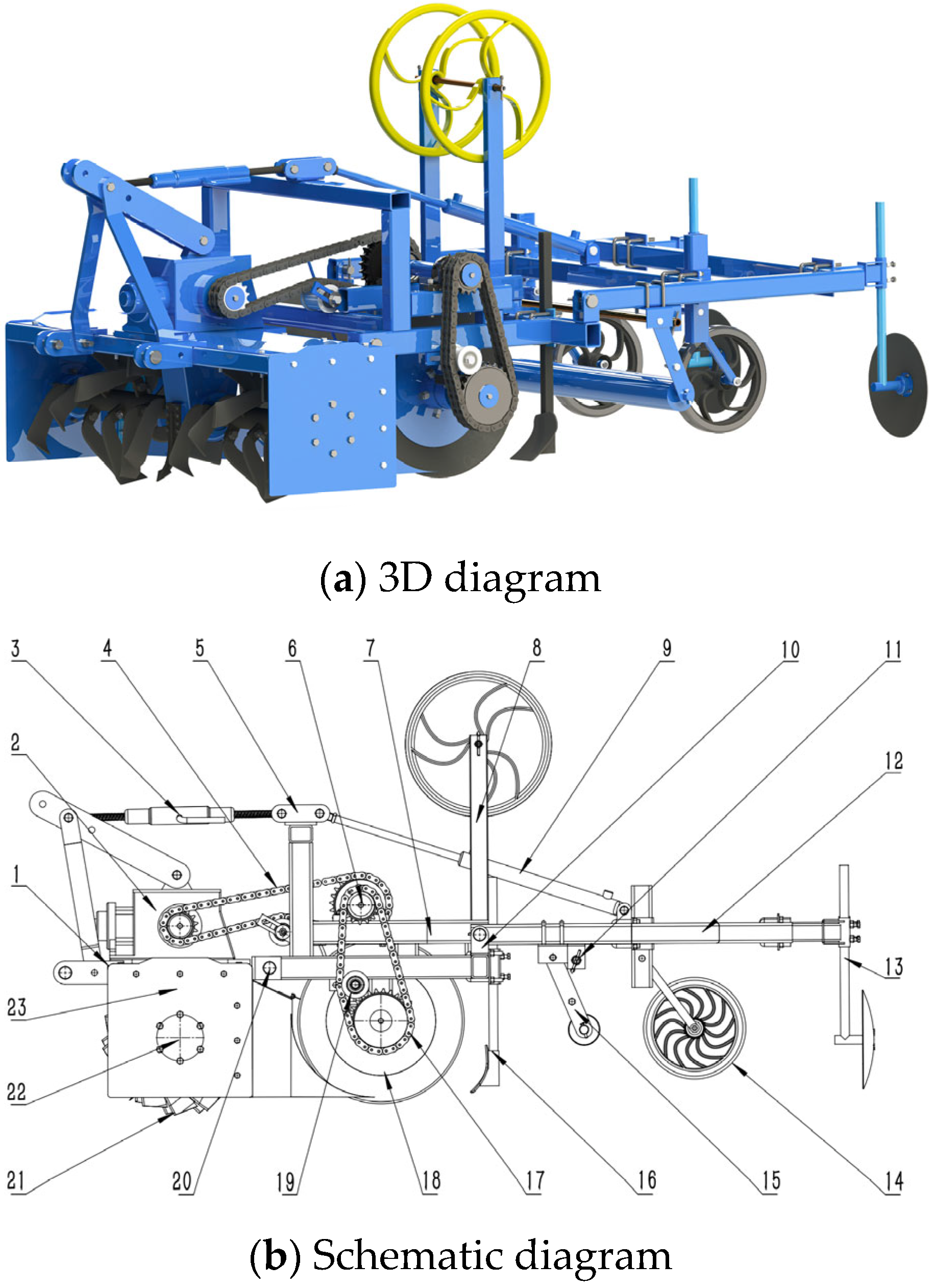
2.2.1. Machine Structure

The designed chili pepper rotary tillage, ridging, and mulching integrated machine is a combined operation unit suspended at the rear of a tractor and driven by a combination of PTO and hydraulic power. As shown in Figure 3, the machine mainly consists of a rotary tillage device, a ridging device, and a mulching device. The rotary tillage device consists of a rotary tillage frame, a rotary tillage housing, a gearbox, a rotary tillage shaft, and rotary tillage blades. The ridging device consists of a ridging frame, a stemming roller group, a transmission shaft, a pre-mulching plow, and a drip tape-laying mechanism. The mulching device mainly includes a mulching frame, a contouring film-pressing roller group, a film support structure, a contouring film-pressing wheel group, and a covering disc component. The rotary tillage device is articulated with the ridging device through a lifting lever, and the ridging device is connected to the mulching device through a hydraulic cylinder hinge.

2.2.2. Working Principle

The integrated chili pepper rotary tillage, ridging, and mulching machine is designed to perform rotary tillage, ridging, and mulching operations in one pass in the field. The rotary tillage device is responsible for soil pulverization and power transmission. During operation, power is transmitted from the tractor to the gearbox, which then adjusts the speed before sending it to the rotary tillage blade shaft. The rotary tillage blades on the shaft perform soil pulverization while simultaneously conveying soil to the ridging device as the tractor moves forward. The ridging device uses a transmission mechanism to rotate the stemming roller group, which compresses the loose soil worked by the rotary tillage device to form ridges. The pre-mulching plow clears the fine soil that slides off the sides of the ridge, ensuring smooth placement of the plastic film on both sides of the ridge. The mulching device, driven by the traction of the machine, moves the contouring film-pressing roller components to lay the film on the ridge. The laid film is then pressed by the contouring film-pressing wheel group to conform to the ridge shape. Finally, the covering disc component of the covering device covers the broken soil from the sides of the ridge onto both sides of the plastic film, creating a ridge structure suitable for chili pepper cultivation.

2.3. Design and Parameter Calculation of the Rotary Tillage and Ridging Device

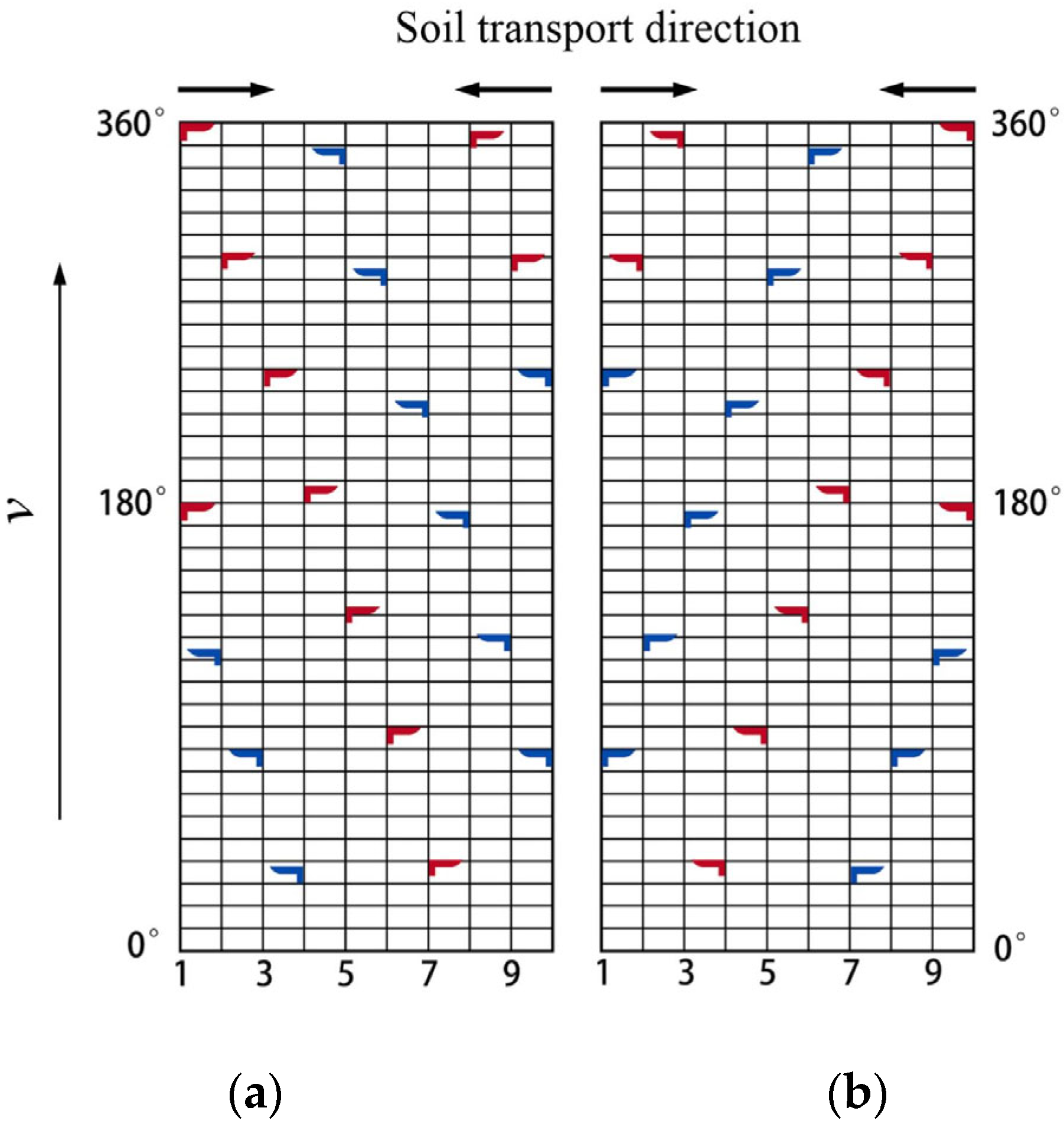
2.3.1. Arrangement of Rotary Tillage Blades

The rotary tillage device is located at the front of the machine and is driven by the tractor’s power take-off (PTO) shaft, which is connected to the gearbox for operation. A middle plow is positioned at the bottom of the gearbox to flip the untilled soil to the sides of the gearbox, ensuring uniform soil pulverization within the working width. As the machine moves forward, the soil that has been tilled is conveyed to the central rear part of the implement by a deflector, providing finely crushed and loosened soil for the ridging device.
The rotary tillage device is located at the front of the machine and is driven by the tractor’s power take-off (PTO) through the gearbox. A middle plow is installed at the bottom of the gearbox to turn the untilled soil to the sides of the gearbox, ensuring uniformity of the rotary tilling within the working width. During the forward movement of the machine, the tilled soil is conveyed by a deflector to the central rear part of the implement [25], providing finely crushed and loose soil for the ridge-forming device.
The rotary tillage device adopts a symmetrically distributed structure design to ensure both uniform soil pulverization and overall machine balance. In order to facilitate soil migration towards the centerline of the ridge, the left and right rotary tillage blade assemblies are adjusted to have their blades rotate towards the centerline. During operation, the soil on both sides is thrown towards the central area of the ridge. Figure 4 illustrates the planar arrangement of the rotary tillage blades. The middle eight rows of rotary tillage blades are installed in the traditional left and right rotation manner, with 20 blades in each left and right rotary tillage blade assembly. The angle between two blades in the same revolution plane is set at 180°, and the angle between adjacent blades along the same spiral line axis is 65°, with a spacing of 75 mm.

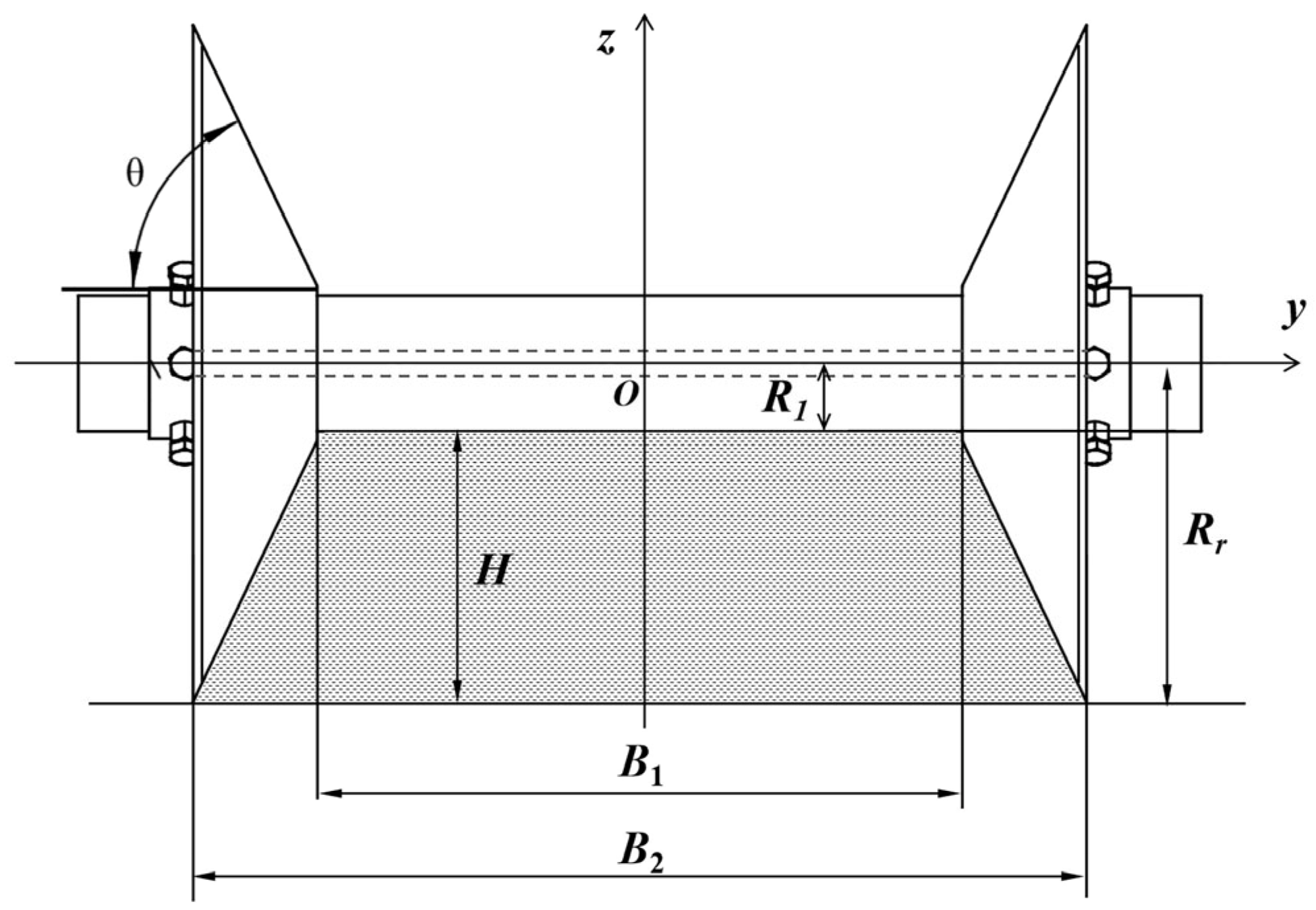
2.3.2. Design of Stemming Roller Group

The ridging device is located in the middle part of the machine and is responsible for compacting the loosened soil after rotary tillage to form ridges. During the process of rotary tillage and ridging, the ridging device faces significant soil resistance. To minimize the power loss caused by soil resistance, the ridging device is designed with a stemming roller group, which transforms the original sliding friction into rolling friction. Additionally, the driving system directly provides power input to the ridging mechanism.
The loosened soil at the front end needs to be compacted by the stemming roller group to form ridges with a trapezoidal cross-section. In the operation process, the shape of the ridges is determined by the external parameters of the stemming roller group. To ensure the compact and shaped formation of the ridges after a single operation cycle, the working surface of the stemming roller group must be consistent with the shape of the ridges. As shown in Figure 5, with the center of the stemming roller group as the coordinate origin, a three-dimensional Cartesian coordinate system is established. Based on the specified agricultural requirements for creating ridges for chili pepper cultivation, the design of the stemming roller group incorporates the following dimensions: the ridge height H = 228 mm, the top width B1 = 545 mm, the bottom width B2 = 755 mm, the rotating radius of the stemming disc Rr = 285 mm, the radius of the pressing roller R1 = 57 mm, and the cone surface angle θ = 64°.

2.3.3. Rotary Tillage Depth

The rotary tillage device and ridging device are the main components responsible for soil engagement, and their relative positions affect the actual operational effectiveness of the equipment. Among them, the rotary tillage depth determines the amount of soil taken and is a crucial factor influencing ridge height and the stability of the ridge shape. During the process of rotary tillage and ridging, the rotary tillage device of the machine loosens the soil, followed by the rolling and shaping of the soil by the stemming roller group. Due to the difference in soil compactness before and after the operation, the volume of soil extracted during rotary tillage should be smaller than or equal to the volume of the compacted ridge. To avoid excessive soil arching and over-compaction of the ridge, it is necessary to maintain a small height difference between the key soil-engaging components before and after the operation. The relative positions of the critical soil-engaging components are shown in Figure 6.
The height difference between the stemming roller group and the axis center of the rotary tillage blade rotation is expressed as:
H c = R d + H R x
where Hc is the height difference between the stemming roller group and the axis center of the rotary tillage device, mm; Rx is the rotational radius of the rotary tillage device, mm; Rd is the radius of the stemming roller group, mm; and H is the height of the ridge, mm.
During machine operation, the soil is initially fragmented by the rotary tillage device, and then, under the rolling and shaping of the stemming roller group, changes occur in the soil voids and layer positions. The cross-section of the ridge before and after the operation is represented as follows:
{ S 1 = L H d S 2 = ( B 1 + B 2 ) H 2 2 S 2 = K a K b S 1
where Hd is the rotary tillage depth, mm; S1 represents the cross-sectional area of the excavated soil, mm2; S2 represents the cross-sectional area of the ridge body, mm2; Ka is the correlation coefficient of soil porosity; and Kb is the correlation coefficient of soil firmness.
The following is calculated from Equation (2):
H d = ( B 1 + B 2 ) H K a K b C
where C is the width of the rotary tillage device, mm; Hd is the depth of rotary tillage, mm; Ka is the correlation coefficient of soil porosity; Kb is the correlation coefficient of soil firmness; H is the height of the ridge after suppression, mm; B1 is the width of the top of the ridge, mm; and B2 is the width of the bottom of the ridge, mm.
Soil porosity is related to the soil capacity before and after the operation of the rotary tillage device [26]. Combined with the soil parameters of chili pepper planting in the Northwest dry zone, the soil firmness is 1.2~1.3 [27], and the soil porosity is often taken as 0.8~1 [28]. In order to achieve the rotary tillage depth and width of the agronomic requirements of chili pepper planting, refer to GB/T 5669-2017 “rotary tillage machinery knives and knives”, combined with the rotary tillage depth, IIT225 rotary tillage knife was selected [29]. The top width of the ridge B1 is 545 mm, the bottom width of the ridge B2 is 755 mm, the height of the ridge H is 228 mm, the width of the rotary tillage device C is 1500 mm, the final determination of the rotary tillage depth Hd is 152~206 mm, and the difference in the height of the rotary center of the stalking roller and rotary knife axle Hc is 60 mm.

2.3.4. Cutting Pitch

The cutting pitch S refers to the distance of the rotary tillage device advancement within the time interval of the rotary tillage knives cutting the soil successively, which has a large influence on the degree of soil fragmentation in this part [30]. If the cutting pitch is too large, the thickness of soil cut by two neighboring rotary knives in the longitudinal plane along the forward direction of the rotary tillage device will also increase, and the principle of rotary tillage knife movement is shown in Figure 7.
The larger the rotary tillage speed ratio of the rotary tillage knife is, the better the cutting effect is, and the cutting pitch S of the rotary tillage knife directly affects the quality of crushed soil and the flatness of cultivated land. According to the soil characteristics of chili pepper planting in the dry zone of Northwest China, the rotary tiller cutting pitch S is 92~140 mm, and the rotary tillage speed ratio is as follows:
λ = 2 π R S Z
where R is the rotary radius of the rotary tillage knife, mm; λ is the rotary tillage speed ratio; S is the soil cutting intercept, mm; and Z is the number of knives in the same rotating surface, pcs.
According to the arrangement of knives on the rotary tillage knife shaft, the number of knives Z in the same rotating surface is 2, the rotary radius of rotary tillage device R is 225 mm, and the rotary tillage speed ratio λ can be calculated as 5.05–7.66 by bringing it into Equation (4) to satisfy the basic conditions of the normal work of a rotary tillage device. When the implement works, the motion of the rotary plow knife is the compound motion of the implement forward and its own rotation, and its trajectory is a cosine line, and the forward speed of the implement is as follows:
V m = n f 60 λ
where λ is the rotary tillage speed ratio; and Vd is the forward speed of the whole machine, m/s.
It is known that the rotary tillage knife shaft rotational speed nf is 253 r/min, and it can be obtained that the forward speed of the whole machine Vm is 0.55~0.83 m/s.

2.3.5. Stalking Roller Group Speed

The rotary tillage device is in positive rotary motion during operation, and the direction of rotation is the same as the forward direction of the implements. For a rotary tillage device in motion for linear and uniform circular motion, if the knife axis is at t = 0 for the coordinate origin, the forward direction of the machine tool for the X-axis, perpendicular to the ground up for the Y-axis, is positive, with XOZ as the projection plane, then the rotary plow knife blade movement trajectory can be expressed as:
{ x = v m t + R cos ( ω t ) z = R sin ( ω t )
where t is the time, s; R is the rotary radius of the rotary cutter, mm; ω is the angular velocity of the rotary cutter blade; and Vm is the forward speed of the implement.
Equation (6) is obtained by derivation for t:
{ v x = v m R ω sin ( ω t ) v z = R ω cos ( ω t )
The cutting speed at the point of the knife edge can be obtained as:
v = v m 2 + ( R ω ) 2 2 v m R ω sin ( ω t )
From Equation (8), the absolute value of the supporting power forward speed Vm is not less than the speed of the rotary cutter to cut the soil V. When the rotary cutter is working, let the depth of rotary cultivation be Hd, the time when the front end of the rotary cutter touches the ground be t, and the angle of entry of the rotary cutter into the soil be as follows:
σ = ω t = arc sin R H d R
Bringing Equation (9) into Equation (7) yields the following:
v x = v m R ω sin ( ω t )
Bringing in the absolute value of Vx gives the following:
σ v m v x R H d
The stalking roller group consists of a stalking disk and suppression roller. For its contact with the wall of the ridge along the horizontal direction with different speeds, in order to ensure the normal operation of the starter device, the stalking disk and the points along the horizontal direction with the speed should be greater than the forward speed of the machine, and the stalking roller group speed should be satisfied as follows:
N 30 v m π ( R H d )
where Hd is the rotary tillage depth, m, and N is the rotational speed of the stalk-building roller group, r/min.
From Equation (12), the main motion parameters of the rotary tillage device are the rotary tillage depth Hd, the forward speed of the machine Vm, and the rotary radius of the rotary tillage device R. The rotary radius of the rotary tillage device is 225 mm, the rotary tillage depth Hd is 152–206 mm, the forward speed of the whole machine Vm is 0.55–0.83 m/s, and the stalking roller group speed N is 108–302 r/min.

3. Simulation of Rotary Tillage and Ridging Operation Process

3.1. Simulation-Related Parameter Settings

To ensure that the simulation process of the rotary tillage and mulching integrated machine conforms to field operation characteristics, the DEM-MBD coupled simulation method was employed for analysis. In order to reduce computational complexity and improve simulation efficiency [31], the machine model was simplified. The rigid connecting components of the machine were merged into a single entity, and the individual parts of the rotary tillage blade assembly and the stemming roller group were integrated. The overall multibody dynamics simulation model of the entire machine was then established using RecurDyn software. As the density, bulk density, and compaction of the surface soil and subsurface soil in the arid regions of Northwest China exhibit significant differences, separate models were established for the 0–14 cm surface soil and the 14–29 cm subsurface soil. A single-sphere model with a radius of 5 mm was created as the base soil particle in EDEM software, and material properties for the soil and the machine were set according to Table 2.
The soil generation process consists of two parts: the deposition process of the base soil and the rapid filling process of the large soil trough. In the Environment settings of EDEM, boundary conditions were set for the X and Y directions. Soil Block models were generated for the surface soil and subsurface soil and imported into the EDEM soil database. A simulated soil tank with a length × width × height of 4800 mm × 1600 mm × 290 mm was recreated. We selected Transfer Material in Bulk Material to export the Soil Block model in the soil database, created the generation area of two kinds of particles, respectively, by Add Block Factory, filled the top soil model in the upper space from 0 to 14 cm, filled the bottom soil model in the lower space from 14 to 29 cm, and created a new model in the contact parameters between the materials in EDEM, and the values are shown in Table 3.
In order to simulate the soil adhesion characteristics in the dry zone of Northwest China, the simulation uses the Hertz–Mindlin with JKR and Hertz–Mindlin with Bonding model, which can produce constraints in the bonded soil particles and produces tangential and normal resistance to the movement of the soil [32] which is suitable for simulating the viscous particles and agglomerated soils, and the model parameters are shown in Table 4.
The cross-section of the ridges after the DEM-MBD coupled simulation of the rotary tillage device and the ridging device is shown in Figure 8. Figure 8a represents the ridge cross-section obtained using only the JKR contact model, while Figure 8b displays the ridge cross-section obtained by incorporating the Bonding contact model on top of the JKR contact model. Figure 8b is the cross-section of the ridges after simulation with the Bonding contact model added on the basis of the JKR contact model. It can be observed that the height of the ridge body without the Bonding model is obviously low, and the soil collapses seriously at the sloping surface of the ridge body. After adding the Bonding model, the height and angle of the ridge meet the design requirements, and there is a groove at the bottom of the ridge, which is more in line with the actual soil. The simulation running time was set to 2 s, and data acquisition was carried out every 0.01 s. The large soil grooves were obtained by fast filling, and the generated soil grooves were saved as a soil model.

3.2. EDEM-RecurDyn Model Construction

In the RecurDyn software, material properties and spatial positioning were adjusted for the equipment. The soil-engaging component was set to have the material properties of 65 Mn. Based on the actual field operation parameters of the machine, the forward speed was set to 0.55–0.83 m/s and the rotation speed of the ridging disc assembly was set to 108–302 m/s for the simulation experiment. In EDEM, the position of the entire machine was adjusted so that the bottom of the ridging disc aligned with the surface of the soil model with a distance of 152–206 mm. The machine was positioned 150 mm away from the edge of the soil trough. The EDEM runtime interface was accessed, with a total simulation duration set to 9 s and a saving interval of 0.01 s. The RecurDyn simulation coupling interface was opened, and the solving process was initiated in the settings.
Figure 9 illustrates the different stages of the coupled simulation of the rotary tillage and ridging process. Prior to 3.77 s, the machine was in the soil penetration stage. Between 5.5 s and 9 s, the machine completely entered the soil trough, initiating the formal rotary tillage and ridging process, during which the machine operated steadily. At the 9 s mark, the machine was about to exit the soil trough, signifying the completion of the rotary tillage and ridging operation and concluding the coupled simulation.
Figure 10 illustrates the variation in the traction resistance of the stemming roller group during the rotary tillage and ridge formation process. From 0 s to 2.6 s, the machine slowly enters the furrow. At 2.6 s, the stemming roller group begins to make contact with the soil. From 2.6 s to 5.2 s, the traction resistance of the stemming roller group continues to increase. During the period of 5.21 s to 9.0 s, the rotary tillage and ridging process officially commences, with the traction resistance of the stemming roller group exhibiting fluctuation within a relatively stable range.
After the rotary tillage and ridging simulation operation, in order to detect the soil firmness of the ridge body, a point 2400 mm away from the boundary of the soil groove was selected as the detection object in the stable area of the operation, and the soil firmness probe model was imported, so that the top of the probe was flush with the top surface of the ridge body. The probe moved in the direction of gravity at a speed of 180 mm/s for 1.00 s, and the probe stopped moving, as shown in Figure 11. At 10.5 s, the soil particles in the monopoly were not disturbed and the force on the probe tended to be constant. Measurements were made on the monopoly probe and the soil firmness was calculated as follows:
P = 4000 F π d 2
where P is the soil firmness, KPa; F is the probe pressure, N; and d is the diameter of the probe, mm.
Based on field investigations and measurements conducted in the arid regions of Northwest China, it was observed that 70% to 80% of the mature chili pepper roots are distributed within the soil layer below the surface, specifically at a depth of 180 mm. To account for the distribution characteristics of chili pepper roots and the stability requirements of the ridges, it was determined that the calculation and statistical analysis of firmness would be carried out at a detection point precisely situated 180 mm below the top surface of the ridges. This location coincides with the central region of the primary distribution range of chili pepper roots, enabling an effective evaluation of ridge stability and ensuring optimal growth and development of the chili pepper roots within the suitable soil layer.

3.3. Simulation Results and Analysis

3.3.1. Experimental Program and Results

The rotary tillage depth, the rotational speed of the stalk-building roller set, and the forward speed of the machine were taken as the test factors, and the range of each factor was as follows: the rotary tillage depth was 152–206 mm, the forward speed of the whole machine was 0.55–0.83 m/s, and the rotational speed of the stalk-building roller set ranged from 108 to 302 r/min. And the central combination test was carried out with the tractive resistance Y1 of the stalk-building roller set and the firmness of the soil Y2 as the test indexes. According to the coded test program, simulation tests were conducted, respectively. The factor coding table is shown in Table 5, and the test program and results are shown in Table 6. X1, X2, and X3 are the factor coding values.

3.3.2. Results and Regression Analysis

The experimental results were analyzed using Design-Expert software to obtain the multivariate regression equations for the traction resistance Y1 of the stemming rollers and the soil compactness Y2, followed by a significance analysis. The variance analysis of the traction resistance Y1 of the stemming rollers is shown in Table 7. The p-values for X2 X3, X22, and X32 are all less than 0.01, indicating a highly significant influence on Y1. The p-values for X1 and X2X3 are less than 0.05, indicating a significant influence on Y1. The p-values for X1X2, X1X3, and X12 are all greater than 0.05, indicating a non-significant influence on Y1. The larger the F-value, the greater the influence of the factor on Y1. The significance of the influences of the various factors and their interactions on Y1, from greatest to least, is X3, X22, X32, X2, X2X3, and X1. By incorporating the non-significant factors into the residual term, the regression equation for the influence of each factor on Y1 is as follows:
Y 1 = 2002.35 5.30 X 1 2.25 X 2 2254.57 X 3 + 0.40 X 1 X 3 + 1.32 X 2 X 3 + 0.02 X 2 2 + 1605.52 X 3 2
The variance analysis of the soil compactness Y2 of the ridges is shown in Table 8. From Table 7, it can be observed that the p-values for X1, X2, X3, X1X3, and X22 are all less than 0.01, indicating a highly significant influence on Y2. The p-value for X12 is less than 0.05, indicating a significant influence on Y2. The p-values for X1X2, X2X3, and X32 are all greater than 0.05, indicating a non-significant influence on Y2. The significance of the influences of the various factors and their interactions on the traction resistance of the stemming rollers, from greatest to least, is X3, X1, X2, X22, X1X3, and X12. By incorporating the non-significant factors into the residual term, the regression equation for the influence of each factor on Y2 is obtained:
Y 2 = 32.39 + 0.70 X 1 0.04 X 2 124.03 X 3 + 0.10 X 1 X 3 0.02 X 2 X 3 62.61 X 3 2

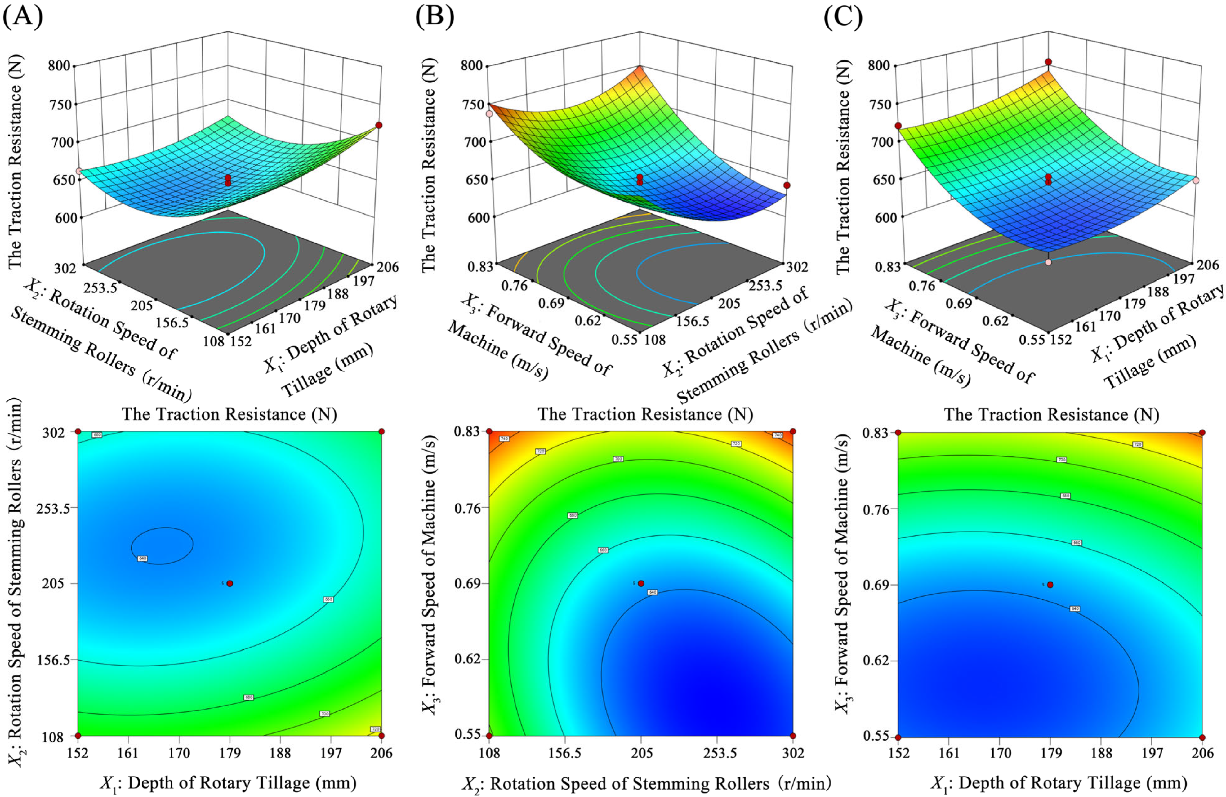
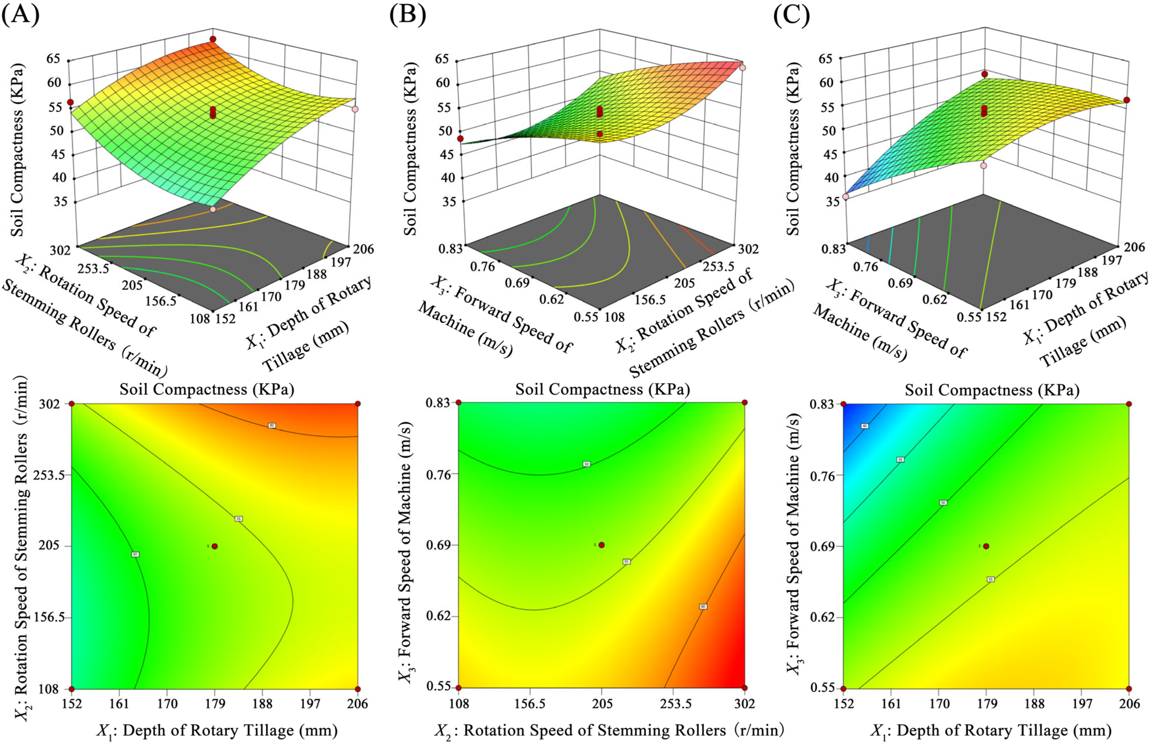
3.3.3. Response Surface Analysis

The response surfaces of the impact of rotary tillage depth, stemming roller speed, and machine forward speed on the traction resistance of the stemming roller group and the firmness of the ridge soil were obtained by analyzing the data using Design-Expert 13 software.
Figure 12 shows the interactive effects on the traction resistance of the stemming roller group. In Figure 12A, with a constant rotary tillage depth, the traction resistance initially decreases and then increases with increasing stemming roller speed, with an optimal range of 205–302 r/min. When the stemming roller speed is constant, the traction resistance decreases and then increases with increasing rotary tillage depth, with an optimal range of 170–188 mm. In Figure 12B, with a constant stemming roller speed, the traction resistance increases with increasing machine forward speed, with an optimal range of 0.55–0.69 m/s. When the machine forward speed is constant, the traction resistance initially decreases and then increases with increasing stemming roller speed, with an optimal range of 205–302 r/min. In Figure 12C, with a constant rotary tillage depth, the traction resistance increases with increasing machine forward speed, with an optimal range of 0.55–0.69 m/s. When the machine forward speed is constant, the traction resistance increases with increasing rotary tillage depth, with an optimal range of 152–188 mm.
Figure 13 shows the impact of interaction effects on the soil compactness of the ridges. As shown in Figure 13A, when the rotary tillage depth is constant, the soil compactness initially decreases and then increases with an increase in stemming roller speed. The optimal stemming roller speed is 253.5–302 r/min. When the stemming roller speed is constant, the soil compactness increases with an increase in rotary tillage depth. The optimal rotary tillage depth is 170–206 mm. As shown in Figure 13B, when the stemming roller speed is constant, the soil compactness decreases with an increase in machine forward speed. The optimal machine forward speed is 0.55–0.69 m/s. When the machine forward speed is constant, the traction resistance increases with an increase in stemming roller speed. The optimal stemming roller speed is 253.5–302 r/min. As shown in Figure 13C, when the rotary tillage depth is constant, the soil compactness decreases with an increase in machine forward speed. The optimal machine forward speed is 0.55–0.62 m/s. When the machine forward speed is constant, the traction resistance increases with an increase in rotary tillage depth. The optimal rotary tillage depth is 170–188 mm.
To obtain the optimal combination of experimental factor levels, the regression model was solved using the Optimization module in the Design-Expert software. The optimization objective function and constraint adjustments were selected as follows:
{ m i n Y 1 ( X 1 X 2 X 3 ) m a x Y 2 ( X 1 X 2 X 3 )
{ 152 X 1 206 108 X 2 302 0.55 X 3 0.83
Through optimization, the best stability during the rotary tillage and ridging process was achieved at a rotary tillage depth of 176 mm, a rotation speed of 283.71 r/min for the stemming roller group, and a forward speed of 0.55 m/s. The predicted soil firmness was 62.87 KPa, and the traction resistance of the stemming roller group was 624.72 N. Simulation validation showed that the soil firmness was 61.26 KPa, and the traction resistance of the stemming roller group was 627.15 N. These results align closely with the optimization findings, confirming the effectiveness of the optimization through field validation. It is basically consistent with the optimized results, and the optimized results are verified in the field.

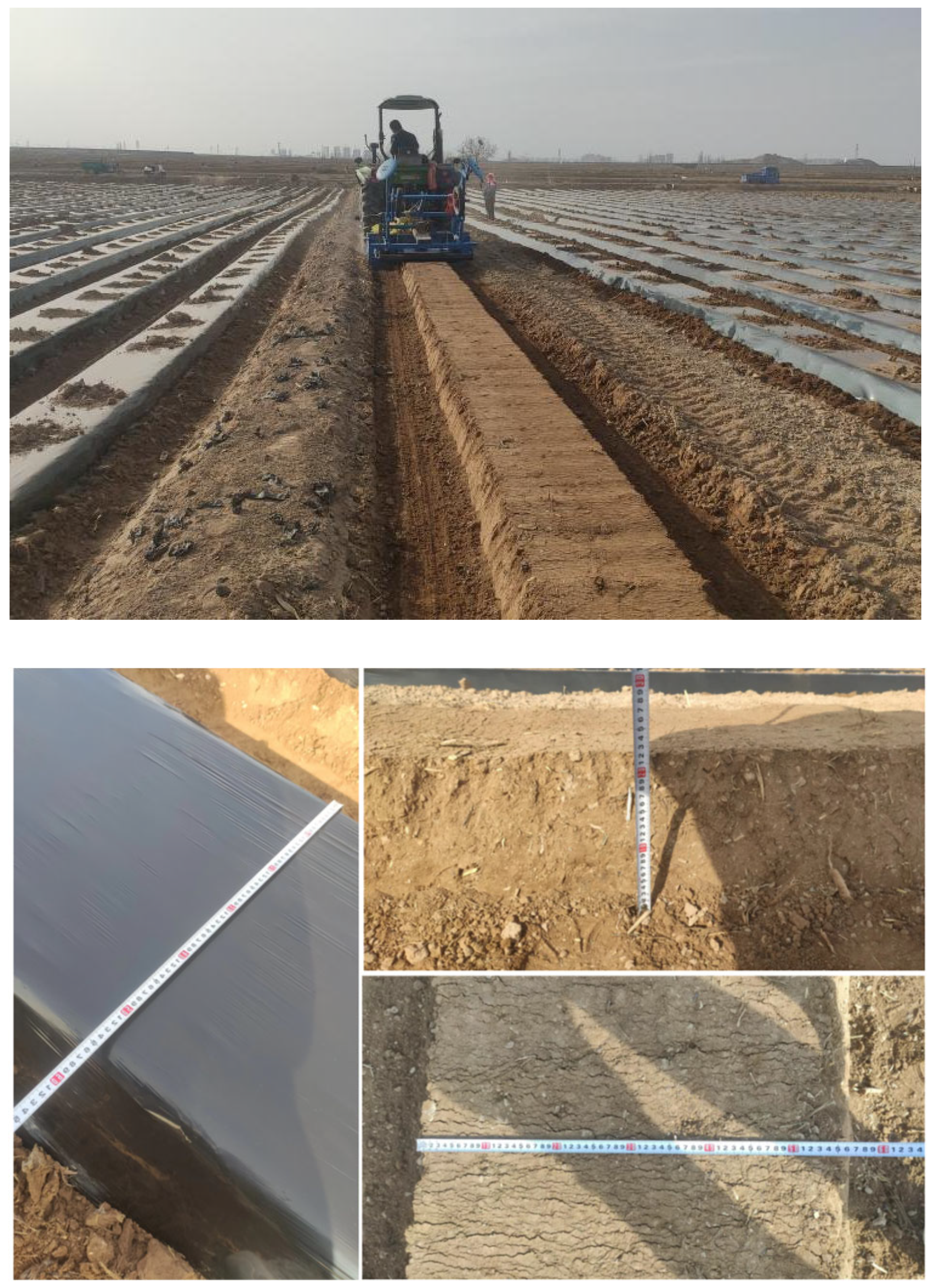
4. Field Verification Test

4.1. Test Scheme

In order to test the working performance of the machine and the indicators of the ridge pattern, a prototype of the rotary tillage and mulching machine for chili peppers was processed and manufactured, and a field test was carried out in March 2023 in Xilin Village, Jingtai County, Baiyin City, Gansu Province (latitude: 37°9′39″ N, longitude: 104°5′28″ E), and the field trial is shown in Figure 14.
During operation, the tractor advances at a speed of 0.55 m/s, and the depth of rotary tillage is 176 mm. To evaluate the requirements for the formation of ridges by the chili pepper rotary tillage and ridging machine, multiple parameters, including ridge spacing, ridge top width, ridge bottom width, and ridge height, need to be measured and statistically analyzed.

4.2. Test Results and Analysis

Test data are shown in Table 9. The stability coefficients of top width, bottom width, and film edge mulch width are higher than 95%, and the test data show that the uniformity of these three indicators is good. In the process of rotary tillage and heaving to ensure the standard and uniformity of the ridge, with the stability coefficients of the three indicators of the ridge height, the distance between the ridges, and the ridge surface flatness between 90% and 95%, and with the stability coefficients according to the analysis of the field conditions, taking into account that the operating field terrain has a slight undulation, the tractor will be manually operated to a small extent of the offset. The distance between the ridges, from one ridge to a larger ridge, causes the magnitude of the stability coefficient of the distance between the ridges to decrease.
Referring to T/CAMA 37-2020 Technical Specification for Mechanized Vegetable Ridge Rising Operations [33] and DB23/T2351-2019 Specification for Evaluation of Ridge Riser Operation Quality [34], the passing rate of the test ridge type indexes were all greater than 91.73%. The soil firmness of the ridge, 66.82 Kpa, is close to the predicted and simulated values, and it meets the growth environment of chili peppers. Therefore, the designed integrated machine for the rotary tillage, ridging, and mulching of chili peppers meets the technical specifications of the mechanized ridging operation.
Figure 15 presents the variation curves of soil compactness after manual ridge formation, simulated ridge formation, and experimental ridge formation. The soil compactness after simulated and experimental ridge formation is higher than that after manual ridge formation. Specifically, the soil compactness in the experimental ridge formation is on average 10.83% higher than that in the simulated ridge formation, which is nearly comparable to the simulated values.

5. Conclusions

  • Aiming at the agronomic requirements and planting mode of chili pepper ridging in the dry zone of Northwest China, a chili pepper rotary tillage and ridging and mulching machine was designed which can realize the integrated operation of rotary tillage, ridging, and film spreading. The theoretical analysis and parameter calculation of the rotary tillage and seeding operation process were completed, and the main parameters such as the arrangement of rotary tillage knives, the cutting pitch of the rotary tillage device, and the running trajectory of the knife blade were determined.
  • Based on DEM-MBD coupled simulation analysis, the central combination test was conducted with the rotary tillage depth, rotational speed of the stalking roller set, forward speed of the implements as the test factors and traction resistance of the stalking roller set and soil firmness as the test indexes. The regression equations were established, and the optimal parameter combinations were determined as follows: the rotary tillage depth was 176 mm, the rotational speed of the stalking roller set was 283.71 r/min, the forward speed of the implement was 0.55 m/s, the soil firmness was 61.26 KPa, and the traction resistance of the stalking roller set was 627.15 N under the same conditions.
  • A field test showed that the effect of the chili pepper rotary ploughing machine is good. The average width of the top of the ridge, the width of the bottom of the ridge, the height of the ridge, the spacing of the ridge, the flatness of the ridge, and the width of the film edge of the mulch were 549.2 mm, 750.5 mm, 222.9 mm, 1173.1 mm, 12.31 mm, and 76.3 mm. The coefficients of stability of the dimensional parameters of the ridge were higher than 91.73%, and the stability of the soil firmness of the ridge was 66.82 KPa. The soil firmness of the ridge was 66.82 KPa, and all the indexes met the agronomic requirements for the chili pepper rotary tillage and ridging process. The design of the chili pepper rotary tillage and ridging mulching integrated machine has effectively improved the operational efficiency of the rotary tillage and ridging processes, resulting in increased yield and quality of chili pepper ridging cultivation and efficient utilization of resources. It contributes to environmental protection and the development of sustainable agriculture.

Author Contributions

Conceptualization, Z.Y.; methodology, Z.Y., K.Z., Y.Z., and J.A.; software, Z.Y. and J.A.; validation, Z.Y., K.Z., Y.Z., and J.A.; formal analysis, Z.Y., K.Z., Y.Z., and J.A.; investigation, Z.Y.; data curation, Z.Y., K.Z., and J.A.; writing—original draft preparation, Z.Y. and K.Z.; writing—review and editing, Z.Y., K.Z., and Y.Z.; visualization, Z.Y., Y.Z., and J.A.; supervision, K.Z. and Y.Z.; project administration, K.Z. and Y.Z.; funding acquisition, K.Z. All authors have read and agreed to the published version of the manuscript.

Funding

The authors acknowledge that this research was supported by Gansu Key Research and Development Program—Industrial Project, under Grant No. 23YFGA0070, the Higher Education Industrial Support Plan Project of Gansu Province, under Grant No. 2021CYZC-29, and the Science and Technology Projects of Lanzhou, under Grant No. 2019-4-55.

Data Availability Statement

Data are contained within the article.

Conflicts of Interest

The authors declare no conflicts of interest.

References

  1. Zhu, L.; Xue, X.R.; Liang, Z.X.; Xu, L.Y.; Yu, G.F.; Tang, Y.; Li, H.X. Correlation between capsaicin content and agronomic traits in pepper (Capsicum annuum L.) germplasm resources. Acta Agric. Zhejiangensis 2023, 35, 862–872. [Google Scholar] [CrossRef]
  2. Ding, Y.; Liu, Y.Y. Effects of plastic mulching cultivation methods on the growth and soil nutrients of peppers in open fields in northern Jiangsu Province. Hubei Agric. Sci. 2023, 62, 115–118. [Google Scholar] [CrossRef]
  3. Fu, J.; Feng, Y.; Lang, X.J.; Wu, P.H. Design and Test of Rotary Tilling Ridger of Puerarialobata. J. Agric. Mech. Res. 2021, 43, 88–90+163. [Google Scholar] [CrossRef]
  4. Wu, C.B.; Li, Z.J.; Zhang, F.G.; Wang, D.L.; Dai, H.F.; Yuan, K. Research Status of Ridging Machinery and Its Application in Tobacco Production in Hilly and Mountainous Areas. Mod. Agric. Sci. Technol. 2022, 13, 100–107. [Google Scholar] [CrossRef]
  5. Wu, Y.W. Design and Experiment of an Integrated Machine for Tobacco Ridging, Fertilizing and Shaping. Master’s Thesis, Henan Agricultural University, Zhengzhou, China, 2021. [Google Scholar]
  6. Yu, F. The Design and Test of Trenching and Ridging Machine for Strawberry Planting in Greenhouse. Master’s Thesis, Anhui Agricultural University, Hefei, China, 2020. [Google Scholar]
  7. Sun, Z.J. Design and Experimental Study of Disk Type Potato Cultivator. Master’s Thesis, Heilongjiang Bayi Agricultural University, Daqing, China, 2021. [Google Scholar]
  8. Liu, Q.H. Design and Experiment of Key Device of Plowshare Potato Cultivator. Master’s Thesis, Northeast Agricultural University, Harbin, China, 2022. [Google Scholar]
  9. Wang, H.N.; Yi, J.G. Design and research of a shed electric tracked rotary cultivation and integral working machine. J. Hebei Agric. Univ. 2020, 43, 116–125. [Google Scholar]
  10. Li, Z.L. Design and Experiment of Potato Trenching and Ridge Raising Device. Master’s Thesis, Huazhong Agricultural University, Wuhan, China, 2023. [Google Scholar] [CrossRef]
  11. Chen, X.T. Design and Test of Successive Compaction Device of Tobacco Ridging, Fertilization and Compaction Machine. Master’s Thesis, Henan Agricultural University, Zhengzhou, China, 2022. [Google Scholar]
  12. Qiu, Y.F. Design and Optimization of Ridging and Film Mulching Machine Applicable to Clay Environment. Master’s Thesis, Central South University, Changsha, China, 2022. [Google Scholar]
  13. YANMAR. BS142CHN. Available online: https://www.yanmar.com/jp/agri/products/implements/bs142ch/ (accessed on 12 January 2024).
  14. Zhang, Q.S.; Cai, J.S.; Yu, L.H.; Fang, Z.; Liao, Q.X.; Bian, Q.W.; Chen, Z.L. Design and Experiment of Ridging Leveling Device for Cold Waterlogged Paddy Field. Trans. Chin. Soc. Agric. Mach. 2024, 1–10. Available online: http://kns.cnki.net/kcms/detail/11.1964.S.20240104.1535.002.html (accessed on 26 January 2024).
  15. Tan, H.W. Design and Experiment of a Combined Seeding Furrow Opener. Master’s Thesis, Northeast Agricultural University, Harbin, China, 2018. [Google Scholar]
  16. Zhang, H.; Guo, X.Y.; Zhang, J.; Yang, R.B.; Wang, W.J.; Qi, S.C. Design and Experiment of Two-stage Combined Ridging Device for Potato Planter. Trans. Chin. Soc. Agric. Mach. 2023, 54, 76–83+92. [Google Scholar]
  17. Wang, J.; Yao, Z.; Xu, Y.; Guo, F.; Guan, R.; Li, H.; Tang, H.; Wang, Q. Mechanism analysis and experimental verification of side-filled rice precision hole direct seed-metering device based on MBD-DEM simulations. Agriculture 2024, 14, 184. [Google Scholar] [CrossRef]
  18. Shi, L.; Zhao, W.; Hua, C.; Rao, G.; Guo, J.; Wang, Z. Study on the intercropping mechanism and seeding improvement of the cavity planter with vertical insertion using DEM-MBD coupling method. Agriculture 2022, 12, 1567. [Google Scholar] [CrossRef]
  19. Li, Y.; Hu, Z.; Gu, F.; Wang, B.; Fan, J.; Yang, H.; Wu, F. DEM-MBD coupling simulation and analysis of the working process of soil and tuber separation of a potato combine harvester. Agronomy 2022, 12, 1734. [Google Scholar] [CrossRef]
  20. Chen, X.; Chen, M.; Liu, M.; Yang, L.; Yang, D.; Wu, H. Design and experiment of sweet potato ridging and forming machine. Agriculture 2023, 13, 1641. [Google Scholar] [CrossRef]
  21. Han, J. Modeling Impacts of Rainfall Harvesting with Ridge and Furrow on Soil Temperature, Moisture, and Yield Using DNDC. Ph.D. Thesis, Northwest A&F University, Xianyang, China, 2013. [Google Scholar]
  22. Zhou, Y.J. Effects of Ratio of Furrow and Ridge with Mulching Patterns on Soil Organic Carbon, Nitrogen Contents and Potato Yield. Master’s Thesis, Ningxia University, Yinchuan, China, 2021. [Google Scholar]
  23. Du, W.B.; Yang, C.L.; Yang, J.P.; Zhang, Q.S.; Yu, J.; Liao, Q.X. Design and Experiment of Cigar Tobacco Adjustable Seed-plot Ridging and Film Spreading Machine. Trans. Chin. Soc. Agric. Mach. 2023, 54, 116–126+295. [Google Scholar]
  24. Yang, T.; Chen, X.B.; Xu, H.; Qin, Z.C.; Liu, S.J.; Liu, J.J. Influence of pepper roots on the spatial movement differentiation of soil moisture in farmland. Trans. Chin. Soc. Agric. Eng. 2023, 39, 141–150. [Google Scholar]
  25. Lin, J.; Zhang, T.J.; Chen, B.; Han, W.; Lv, Q.L.; Wang, J.Q. Design and Test of Subsoiling Rotary Rilling and Rilling Combined Operating Machine. Trans. Chin. Soc. Agric. Mach. 2019, 50, 28–39. [Google Scholar] [CrossRef]
  26. Strudley, M.W.; Green, T.R.; Ascough, J.C. Tillage effects on soil hydraulic properties in space and time: State of the science. Soil Tillage Res. 2008, 99, 4–48. [Google Scholar] [CrossRef]
  27. Lv, J.Q.; Liu, Q.H.; Yang, D.Q.; Li, J.C.; Liu, Z.Y.; Yu, J. Design and Test of Key Components of Ploughshare Potato Field Cultivator in Sandy Loam. Trans. Chin. Soc. Agric. Mach. 2021, 52, 27–39. [Google Scholar] [CrossRef]
  28. Liu, H.; Zhang, Q.S.; Liao, Y.T.; Wei, G.L.; Du, Z.; Liao, Q.X. Design of Plow-rotary and Roll-forming Revetment Style Seed Bed Ridging Device of Combined Precision Seeder for Brassica chinensis. Trans. Chin. Soc. Agric. Mach. 2021, 52, 40–48+77. [Google Scholar] [CrossRef]
  29. GB/T 5669-2017; Rotary Tillage Machinery Blades and Holders. China National GB Standard Research: Nanjing, China, 2017.
  30. Makarov, S.A.; Danilin, A.V.; Levchenko, G.V.; Kalinichenko, E.B.; Ivaniva, L.M. Investigation of kinematic parameters of the rotary working body of a universal rotary cultivator. IOP Conf. Series. Earth Environ. Sci. 2022, 979, 012058. [Google Scholar] [CrossRef]
  31. He, X.; Lv, Y.; Qu, Z.; Wang, W.; Zhou, Z.; He, H. Parameters optimization and test of caterpillar self-propelled tiger nut harvester hoisting device. Agriculture 2022, 12, 1060. [Google Scholar] [CrossRef]
  32. Xiao, M.H.; Niu, Y.; Wang, K.X.; Zhu, Y.J.; Zhou, J.B.; Ma, R.Q. Design of Self-excited Vibrating Rotary Tiller and Analysis of Its Performance in Reducing Torsion and Consumption. Trans. Chin. Soc. Agric. Mach. 2022, 53, 52–63. [Google Scholar] [CrossRef]
  33. T/CAMA 37-2020; Technical Specification for Mechanized Vegetable Ridge Rising Operations. Chinese Agricultural Machinery and Equipment Comprehensive Group Standard Research: Nanjing, China, 2020.
  34. DB23/T2351-2019; Specification for Evaluation of Ridge Riser Operation Quality. Chinese Regional Standard Research: Heilongjiang, China, 2019.
Figure 1. Measurement of mature chili pepper plants.
Agronomy 14 00446 g001
Figure 2. Cross-sectional view of chili pepper ridging. H is the compressed ridge height, mm; B1 is the ridge top width, mm; B2 is the ridge base width, mm; L is the center distance between two rows of ridges, mm.
Agronomy 14 00446 g002
Figure 3. Overall structure of the integrated chili pepper rotary tillage, ridging, and mulching machine: (1) rotary tillage frame; (2) gearbox; (3) lifting lever; (4) power input sprocket group; (5) lifting hinge component; (6) transmission shaft assembly; (7) ridging frame; (8) drip tape-laying mechanism; (9) hydraulic cylinder; (10) mulching device hinge component; (11) film support structure; (12) mulching frame; (13) covering disc component; (14) contouring film-pressing wheel group; (15) contouring film-pressing wheel group; (16) pre-mulching plow; (17) power output sprocket group; (18) stemming roller group; (19) nylon tension roller; (20) rotary tillage and ridging hinge component; (21) 225 rotary tillage blade; (22) rotary tillage blade shaft; (23) rotary tillage housing.
Agronomy 14 00446 g003
Figure 4. Schematic diagram of planar arrangement of rotary tillage blades. (a) Left rotary tillage blade assembly. (b) Right rotary tillage blade assembly. The red represents the rotary tillage blades that face towards the inside of the machine, while the blue represents the rotary tillage blades that face towards the outside of the machine.
Agronomy 14 00446 g004
Figure 5. Schematic diagram of ridging roller operation.
Agronomy 14 00446 g005
Figure 6. Schematic diagram of soil-engaging components in operation.
Agronomy 14 00446 g006
Figure 7. Schematic diagram of rotary plow knife movement principle. Where ω is the rotary angle of the rotary tillage knife, rad/s; Vd is the forward speed of the whole machine, m/s; Hd is the rotary tillage depth, mm; S is the soil cutting intercept, mm; R is the rotary radius of the rotary tillage knife, mm; O is the coordinate origin; θ is the rotation angle, degrees; and Xd is the distance traveled along the x-axis per unit time, mm.
Agronomy 14 00446 g007
Figure 8. Comparison of the cross-section of the contact model monopoly body. (a) JKR parameter model only. (b) Combined JKR parameter model and Bonding parameter model.
Agronomy 14 00446 g008
Figure 9. Simulation of the rotary tillage and ridge-forming process.
Agronomy 14 00446 g009
Figure 10. Traction resistance variation of the stemming roller group.
Agronomy 14 00446 g010
Figure 11. Soil compactness test. (a) Cross-sectional diagram of the ridge body. (b) Force diagram of the probe.
Agronomy 14 00446 g011
Figure 12. The response surface plots of the interaction effects on the traction resistance of the stemming rollers. (A) is the interaction diagram between X1 and X2, (B) is the interaction diagram between X2 and X3, and (C) is the interaction diagram between X1 and X3.
Agronomy 14 00446 g012
Figure 13. The response surface plots of the interaction effects on the soil compactness of the ridges. (A) is the interaction diagram between X1 and X2, (B) is the interaction diagram between X2 and X3, and (C) is the interaction diagram between X1 and X3.
Agronomy 14 00446 g013
Figure 14. Field test.
Agronomy 14 00446 g014
Figure 15. Soil compactness variation curve.
Agronomy 14 00446 g015
Table 1. Comparison of ridge-making machinery types and their advantages and disadvantages.
TypesPrinciple of OperationAdvantagesDisadvantages
Disc plough ridge machineryThis model relies on tractor traction and soil resistance to complete ridging. By adjusting the disc size, inclination angle, and working width, it can complete the crushing and turning of soil [7].This machine has a simple structure, is lightweight for transportation, and has low manufacturing costs.The adjustment steps for the disc plough are cumbersome and difficult, and it is not suitable for clayey soil plots, which poses significant operational limitations.
Plowshare-type ridge machineryThis model relies on tractor traction to make the plowshare type cut the soil and complete the ridging. The curved shape of the plowshare helps lift the soil as it cuts and creates a raised mounding shape.This machine has a high productivity, convenient power supply, simple structure, reliable operation, and low operating costs [8].This machine requires a higher traction resistance. Additionally, when excavating channels, it is necessary to use leveling tools or manually level the soil on both sides of the ditch to ensure the smoothness of the ridges.
Rotary tillage ridge machineryThis model uses high-speed rotary tillage knives to cooperate with the ridging mechanism for ridging, and then various types of ridging parts are extruded to form a ridge [9].This machine has a high productivity, convenient power supply, reliable operation, low traction resistance, and high soil fragmentation rate, and it produces uniformly stable ridges.This machine features a complex design and structure. Additional design and adjustments are necessary to accommodate the varying growth conditions of different crops, resulting in higher investment and operational costs.
Table 2. Material property parameters.
Parameter TypeDensity (kg·m−3)Poisson’s RatioShear Modulus (Pa)
Top soil15350.406.0 × 107
Sub soil17550.426.0 × 107
65 Mn78600.297.9 × 1010
Table 3. Material contact parameters.
Contact ParametersCollision Recovery CoefficientStatic Friction CoefficientDynamic Friction Coefficient
Top soil-Top soil0.130.320.14
Top soil-Sub soil0.1450.330.155
Sub soil-Sub soil0.160.340.17
Top soil-65 Mn0.60.310.11
Sub soil-65 Mn0.60.640.13
Table 4. Soil contact model parameters.
Parameter NameNumerical Value
Bonding radius/(mm)7
Normal critical stress/KPa235
Shear critical stress/KPa186
Normal stiffness coefficient/(N·m−2)2.4 × 106
Shear stiffness coefficient/(N·m−2)1.8 × 106
Top soil-Top soil surface energy/(J·m−2)5.6
Top soil-Sub soil surface energy/(J·m−2)6.4
Sub soil-Sub soil surface energy/(J·m−2)7.2
Table 5. Test factors and levels.
LevelsFactors
Depth of Rotary Tillage
X1 (mm)
Rotation Speed of Stemming Rollers
X2 (r/min)
Forward Speed of Machine
X3 (m/s)
−11521080.55
01792050.69
12063020.83
Table 6. Experimental program and results.
No.FactorsResponse Values
X1X2X3Y1/NY2/Kpa
10−1−1707.7059.40
2000644.1353.67
301−1643.2763.70
4−110663.3756.54
5000647.1052.24
6110670.4362.56
7−10−1622.1053.38
81−10724.3055.10
9000654.4755.10
10011746.4251.95
11−101722.7135.61
12−1−10699.4945.36
13000640.6154.24
140−11738.8948.80
15101756.2054.24
16000635.4752.81
1710−1649.4757.11
Table 7. Variance analysis of traction resistance of the stemming rollers.
SourceFreedomSum of SquaresMean SquareF-Valuep-ValueSignificance
Mode930,063.823340.4221.050.0003**
X111074.861074.866.770.0353*
X212697.082697.0816.990.0044**
X3114,593.1514,593.1591.95<0.0001**
X1X2178.7778.770.49630.5039
X1X319.369.360.05900.8150
X2X311294.561294.568.160.0245*
X121585.85585.853.690.0961
X2214653.814653.8129.320.0010**
X3214169.484169.4826.270.0014**
Residual error71110.91158.70
Lack-of-fit3908.05302.685.970.0586
Pure Error4202.8750.72
Cor Total1631,174.73
Note: ** means very significant (p < 0.01); * means significant (0.01 < p < 0.05).
Table 8. Variance analysis of soil compactness experimental response surface.
SourceFreedomSum of SquaresMean SquareF-Valuep-ValueSignificance
Mode9635.4270.6018.580.0004**
X11181.64181.6447.800.0002**
X2185.0985.0922.390.0021**
X31231.02231.0260.790.0001**
X1X213.463.460.91040.3718
X1X3155.5055.5014.610.0065**
X2X310.33060.33060.08700.7766
X12122.2722.275.860.0460*
X22153.9053.9014.180.0070**
X3216.346.341.670.2374
Residual error726.603.80
Lack-of-fit321.467.155.570.0653
Pure Error45.141.28
Cor Total16662.02
Note: ** means very significant (p < 0.01); * means significant (0.01 < p < 0.05).
Table 9. Results of field trials.
ParameterData
Ridge heightMean value/mm222.9
Stability coefficient%93.36
Ridge spacingMean value/mm1173.1
Stability coefficient%91.73
Ridge top widthMean value/mm549.2
Stability coefficient%97.34
Ridge bottom widthMean value/mm750.5
Stability coefficient%95.29
Soil compactnessMean value /KPa66.82
Stability coefficient%90.76
Width of soil covering the film edgeMean value/mm76.3
Stability coefficient%96.10
Surface smoothness of the ridgesMean value/mm12.31
Stability coefficient%93.29
Disclaimer/Publisher’s Note: The statements, opinions and data contained in all publications are solely those of the individual author(s) and contributor(s) and not of MDPI and/or the editor(s). MDPI and/or the editor(s) disclaim responsibility for any injury to people or property resulting from any ideas, methods, instructions or products referred to in the content.

