Article

Analysis of Breaking and Separating Characteristics of Potato–Soil Aggregates Based on the New Type of Swing Separation Sieve

College of Mechanical and Electrical Engineering, Inner Mongolia Agricultural University, Hohhot 010018, China
*
Author to whom correspondence should be addressed.
Agronomy 2024, 14(6), 1272; https://doi.org/10.3390/agronomy14061272
Submission received: 11 April 2024 / Revised: 20 May 2024 / Accepted: 10 June 2024 / Published: 12 June 2024
(This article belongs to the Section Precision and Digital Agriculture)

Abstract

:
In response to the significant challenge posed by the trade-off between the efficiency of separating potato soil and minimizing potato peel damage in the 4SW-170 potato excavator, this study focused on enhancing the design of the swing separation sieve. The objective was to develop a novel separation sieve comprising three distinct orders of sieve surfaces. Building upon this foundation, the EDEM-Adams coupled simulation method was employed to explore the fragmentation and separation attributes of potato–soil aggregates. This investigation aimed to elucidate the behavior of potato–soil aggregates within the operational scope of the novel swing separation sieve. Subsequently, the optimized parameters were validated through field tests. The findings indicate a direct correlation between the fracture ratio of the cohesive bond and the crank speed, illustrating an increase in the former with higher crank speeds. Conversely, an inverse relationship exists between the fracture ratio and the sieve inclination angle, demonstrating a decrease in the ratio as the sieve inclination increases. At a machine speed of 1.9 km/h, the fracture ratio of the cohesive bond attains its peak value. The force exerted on potatoes at their maximum point escalates with rising crank speed but diminishes with increasing machine speed. Conversely, the effect of sieve inclination on the peak force applied to the potatoes is deemed inconsequential. The most effective parameter configuration for the separation sieve comprises a crank speed of 180 revolutions per minute (r/min), a machine speed of 1.9 km per hour (km/h), and a sieve inclination of 14.4°. Field trials have confirmed that the parameter combination yielded a potato detection rate of 98.01% and a mere 0.68% rate of potato skin breakage, meeting the stipulated technical specifications of the potato harvester.

1. Introduction

Potatoes are globally recognized as a crucial staple crop due to their extensive cultivation area and high production levels. By 2015, it gained recognition as the fourth-largest primary crop, following rice, wheat, and maize. This acknowledgment catalyzed an extensive expansion in potato cultivation and a significant enhancement in its overall yield [1,2,3].
Statistical data indicate that in 2021, China’s potato cultivation area surpassed 70 million hectares, yielding a total production of 97 million tons. This output represents roughly a quarter of the global potato planting area and production [4,5]. The ongoing expansion of the potato planting area and the progressive rise in production levels have underscored the critical importance of mechanized harvesting in influencing both the yield and quality of potatoes [6,7,8]. Presently, potato harvesting methods primarily encompass segmented harvesting and combined harvesting. Owing to China’s distinctive agronomic and geographical characteristics, segmented harvesting persists as the predominant method for potato harvesting across most regions [9]. This process entails employing a potato digger to unearth the potatoes, depositing them onto the ground, and subsequently manually gathering and bagging the produce [10].
The potato–soil separation device plays a pivotal role in segmented harvesting machinery, exerting a direct influence on both the yield and quality of potato harvests. Commonly employed potato–soil separation devices encompass the chain-type elevator [11,12], finger wheel [13], roller push [14], disk grid [15], vibrating sieve [16,17], and the combination of rod chain with swing sieve [18]. These diverse machines have seen varying degrees of application and promotion in major potato-producing regions. Nevertheless, the inherent conflict between soil separation efficiency and potato preservation continues to pose a bottleneck, limiting the advancement of potato harvesting machinery [19,20,21,22,23].
Within the spectrum of current potato harvesting machinery, the rod chain with swing sieve potato digger stands out for its high soil separation efficiency and robust adaptability across various soil types [24]. The system relies on the swing separation sieve as its primary component for potato–soil separation. While effectively separating potatoes from soil aggregates, this mechanism also induces a certain level of potato damage.
Analysis revealed that the initial swing separation sieve comprised two layers of sieve surfaces. Owing to constraints within the sieve structure, both layers exhibited strong potato–soil separation capacity and material conveying capability. Within the potato–soil separation process, the initial sieve surface effectively separated the majority of potato–soil aggregates. Nevertheless, as the potatoes transitioned to the second sieve surface, they sustained damage due to the absence of shielding provided by soil and root systems. Hence, this study suggests an enhanced design for the initial swing separation sieve to maintain its proficiency in potato–soil separation while mitigating potato skin damage.
Concurrently, a newly developed swing separation sieve featuring three layers of sieve surfaces serves as the mechanical framework. This investigation utilizes a combination of discrete element simulation and field experiments to examine the attributes of potato–soil aggregate fragmentation throughout the separation process. Through the acquisition of optimal parameter settings for the new separation sieve, this research endeavors to offer theoretical and technical backing to resolve the inherent contradiction between potato–soil separation efficiency and potato damage. The outcomes of this study are poised to provide valuable insights into addressing this issue and enhancing the performance of potato harvesting machinery.

2. Materials and Methods

2.1. Improved Design of the Swing Separation Sieve

2.1.1. Improvement of Separation Sieve Motion Mechanism

In the process of engineering a novel mechanical structure, it was imperative to evaluate the presence of precisely defined motion characteristics within the mechanism [21,22]. For a mechanism to exhibit determinate motion, it necessitated having the number of driving links equivalent to its degree of freedom. The fundamental formula employed for determining the degree of freedom in planar mechanisms is outlined below:
F = 3 n 2 P L P H
The formula breakdown was as follows: ‘ F ’ represented the degree of freedom in planar mechanisms, ‘ n ’ denoted the number of movable links, ‘ P L ’ signified the number of lower pairs in the planar mechanism, while ‘ P H ’ represented the number of higher pairs in the planar mechanism.
The refined design of the separation sieve mechanism in this investigation could be depicted as a planar motion mechanism, as illustrated in Figure 1.
The separation sieve mechanism comprised 8 components, where component 1 constituted the frame, while the remaining 7 components were movable links. The components interconnected via rotary pairs formed compound hinges at points D and F. Consequently, the mechanism comprised 10 lower pairs ( P L ) and 0 higher pairs ( P H ), resulting in a constraint equation of 2 P L + P H = 20 . Consequently, the degree of freedom ( F ) for this transmission mechanism was 1. Considering the crank as the driving link, the mechanism fulfilled the criteria for determinate motion and exhibited a distinctive, well-defined motion trajectory.

2.1.2. Theoretical Analysis of Separation Sieve Acceleration

The movement of potato–soil aggregates on the swing separation sieve was governed by the dynamic and kinematic interactions between the sieve and the aggregates. The efficiency of crushing and separation was affected by the acceleration of the swing separation sieve. Thus, it was essential to conduct a theoretical analysis of the acceleration of the swing separating sieve, which served as a foundation for determining the structural parameters of the sieve and selecting factors for the simulation test of potato–soil agglomerate crushing and separation.
Figure 1 illustrates the structure of the swinging separation sieve. The first-order sieve surface was hinged to the frame via the front and rear hanging rods, DC and EF. The crank AB drove the connecting rod BD, causing the first-order sieve surface to reciprocate. Motion simulation of the separation sieve showed that the sieve surface underwent a reciprocating arc motion, with the motion trajectory being much shorter than the length of the connecting rod. For analytical convenience, the motion trajectory of the sieve surface was simplified to a straight line. Considering the vibration direction as the S-axis and taking the equilibrium position of the sieve surface as the initial point for displacement and time, the displacement of the separation sieve could be derived as follows:
s = r sin ω t
where “ s ” is the displacement of separating sieve (m), “ r ” is the crank radius (mm), and “ ω ” is the crank angular speed (rad/s); “ t ” is the time (s).
From this, the speed and acceleration of the separating sieve were derived as follows:
v = r ω cos ω t
a = r ω 2 sin ω t
where “ v ” is the speed of separating sieve (m/s), and “ a ” is the acceleration of the separating sieve (m/s2).
By establishing the xy coordinates parallel and perpendicular to the sieve surface (as shown in Figure 1), with the x-axis pointing toward the tail of the separating sieve, the components of the sieve’s acceleration along the x and y axes were, respectively,
a x = r ω 2 sin ω t cos β + α
a y = r ω 2 sin ω t sin β + α
where “ a x ” is the component of the acceleration of the separating sieve in the x-axis (m/s2), “ a y ” is the component of the acceleration of the separating sieve in the y-axis (m/s2), “ α ” is the angle of inclination of the sieve surface (°), and “ β ” is the direction angle of vibration of the separation sieve (°).
From Equations (5) to (6), it was evident that variations in factors such as crank radius (r), sieve surface inclination angle (α), vibration direction angle (β), and crank speed (n) would alter the acceleration of the swing separating sieve, thereby affecting the efficiency of the potato–soil aggregate crushing and separation process.

2.1.3. Improvement of Separation Sieve Structure

Based on the theoretical analysis of separation sieve acceleration in Section 2.1.2, it was evident that meeting the acceleration requirement was crucial for the separation sieve. Therefore, combining the theoretical analysis of separation sieve acceleration with previous research [25,26,27], a new third-order separation sieve was designed to ensure its structural dimensions met the operational requirements.
Separation of potatoes and soil occurred primarily on the first order of the new swing separator sieve. Simultaneously, a small amount of soil and roots were conveyed and separated on the second-order sieve, which also cushioned the potatoes and reduced damage. The remaining broken hard clods of soil and potatoes were conveyed only on the third order of the sieve, eventually being laid on the surface. The acceleration parallel and perpendicular to the sieve surface, in the direction of the back-and-forth motion of the swing separator sieve, determined the performance of the separator sieve. The acceleration parallel to the sieve surface primarily determined the ability of the separating sieve to convey materials, while the acceleration perpendicular to the sieve surface primarily determined its ability to separate potatoes and soil. Therefore, the acceleration perpendicular to the sieve surface should decrease from the first to the third order, while the acceleration parallel to the sieve surface should increase from the first to the third order. According to relevant research, conclusions showed [26] when the lengths of the first-order, second-order, and third-order suspension rods and the crank connecting rod were 270 mm, 370 mm, 570 mm, and 1050 mm, respectively, the acceleration perpendicular to the sieve surface from the first order to the third order is 23.72 m/s2, 12.88 m/s2, and 10.61 m/s2 in order, and the acceleration parallel to the sieve surface from the first to the third order was 15.59 m/s2, 14.46 m/s2, and 14.77 m/s2 in order, which meets the design requirements of the new swing separating sieve.
On the original separation sieve with a sieve surface length of 1000 mm, the segment from 600 mm to 1000 mm was a soil-free sieve surface, while the segment from 100 mm to 600 mm was a soil-containing sieve surface [25]. Therefore, the first-order sieve surface was designed to be 400 mm long, and the second- and third-order sieve surfaces were each designed to be 300 mm long. The length of the sieve surface connecting rod was primarily determined by the length of the sieve surface. To ensure that issues such as potato jamming and potato leakage did not occur during the operation of the separation sieve, the connecting rod length for the first- and second-order sieves was designed to be 370 mm, and for the second- and third-order sieves, it was designed to be 270 mm. The structural parameters of the separating sieve are shown in Table 1.

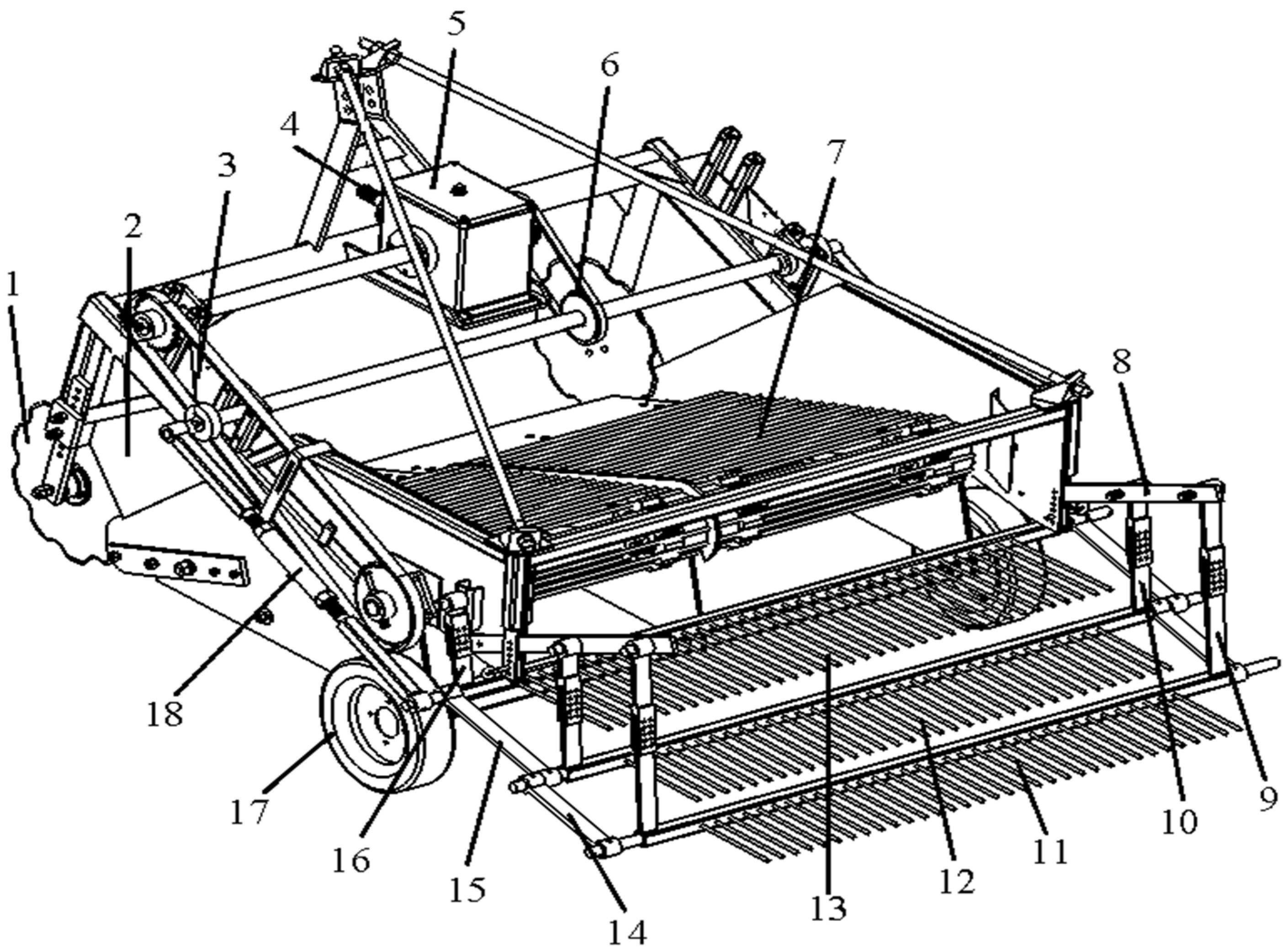
2.1.4. Structure and Working Principle of the Novel Swing Separation Sieve

Installation of the enhanced swing separation sieve onto the potato digger led to the development of the new 4SW-170 model potato digger (Inner Mongolia Agricultural University Machinery Manufacturing Plant, Hohhot, China), depicted in Figure 2. This machinery primarily comprised a frame, gearbox, digging shovel, lifting chain, and an innovative swing separation sieve. The separation sieve included a power input shaft, gearbox, sprocket transmission mechanism, crank, connecting rod, three-tier sieve surfaces, and the sieve frame. All sieve bars in the swing separation sieve featured rubber coating.
While the potato digger operated, soil cutting discs, positioned on each side, severed potato sprouts, weeds, and additional vegetation. The harvested yield predominantly comprised potatoes and soil, along with minor quantities of roots and weeds entangled within the potato–soil aggregates. The digging shovel raised these aggregates and transferred them to the lifting chain. During the backward motion of the lifting chain, roughly 20% to 30% of the soil descended through gaps amidst the bars, whereas the residual aggregates progressed toward the swing separation sieve, featuring three-tier sieve surfaces.
Driven by the crank-linkage mechanism, the separation sieve’s sieve surfaces experienced reciprocal motion. Throughout this process, the potato–soil aggregates underwent fragmentation and separation across each tier of the sieve surface. Soil sifted through the openings between the sieve bars descended to the ground, while the potatoes traveled to the edge of the sieve surface and were neatly arranged on the ground in a linear fashion.

2.2. Establishment of the Potato–Soil Aggregate Model

The discrete element simulation primarily encompassed particle interactions, encompassing collisions, friction, and shearing occurrences among particles. Hence, the critical selection of a suitable particle contact model was imperative. The Hertz–Mindlin model, incorporating bonding, was utilized in this study to simulate the bonding interactions among soil particles and between potato and soil particles. The model within the EDEM 2018 discrete element simulation software created cohesive bonds among particles, establishing bonding connections and cohesive forces within a specified tensile range. If adjacent particles or particles interacting with objects undergo alterations in both tangential and normal forces, and these forces surpass the critical fracture threshold of the bonding bond, the bond initiated fracture.

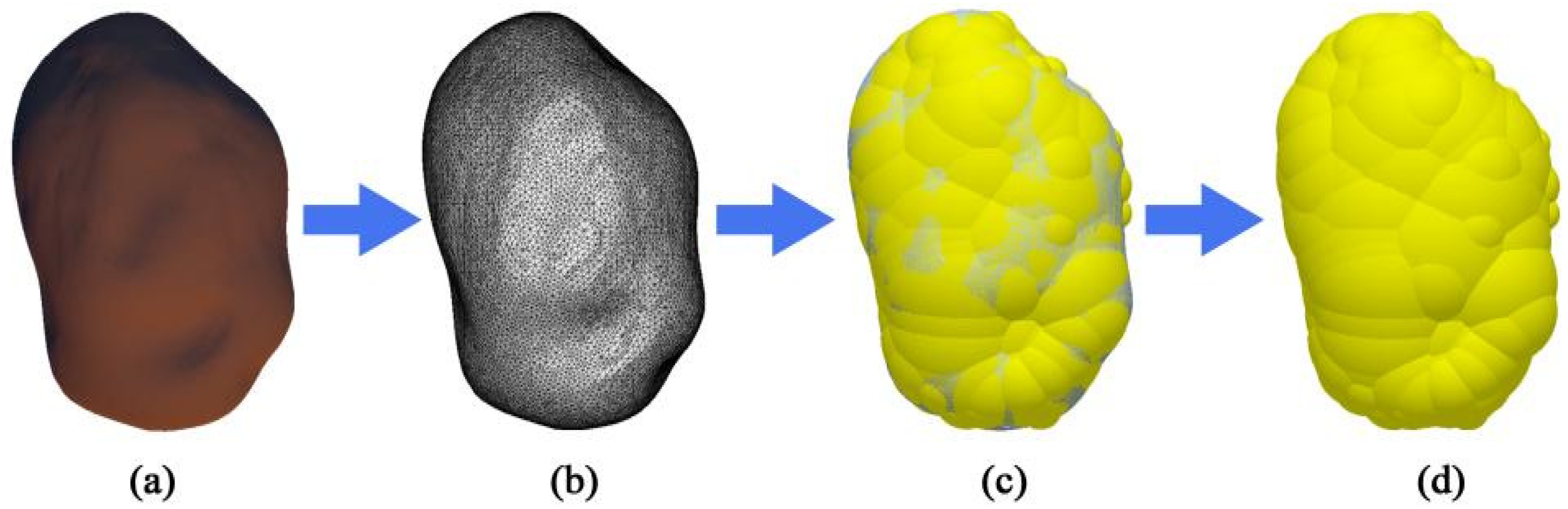
2.2.1. Establishment of the Potato Model

The potato model was acquired by employing a 3D scanner (Beijing 3D World Co., Ltd., Beijing, China) to capture the potato’s shape through 3D scanning, followed by the application of the multi-sphere fast, automatic filling method for its creation. Following the 3D scanning of the initial potato model (Figure 3a), a 3D image displaying triangular mesh division was produced (Figure 3b). Subsequently, the mesh was imported into the EDEM discrete element simulation software, where the multi-sphere fast, automatic filling method was utilized to populate the mesh, culminating in the discrete element simulation model of the potato (Figure 3d).

2.2.2. Soil Model Establishment

The calibration process for soil contact parameters involved determining the physical repose angle, performing simulation experiments via the Plackett–Burman experimental design, executing steepest ascent trials, and conducting response surface experiments utilizing the Box–Behnken design. Ultimately, the soil contact parameters for a water content of 12% conditions were delineated, as shown in Table 2 [20].
Preprocessing involved the essential determination of the spatial coordinates for each soil particle before commencing the formal simulation experiments. The soil particle filling employed the Hertz–Mindlin (no slip) particle contact model, and Figure 4 illustrates the exported three-dimensional geometric coordinates of the soil particles.

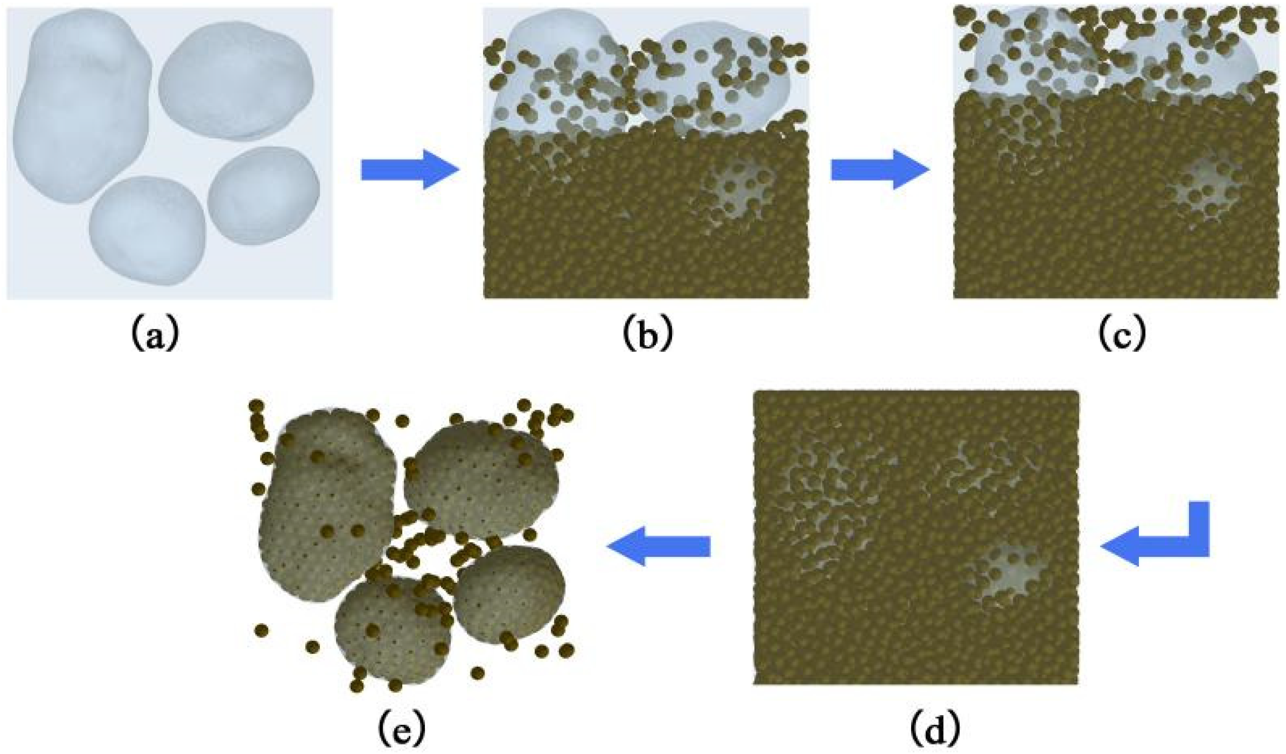
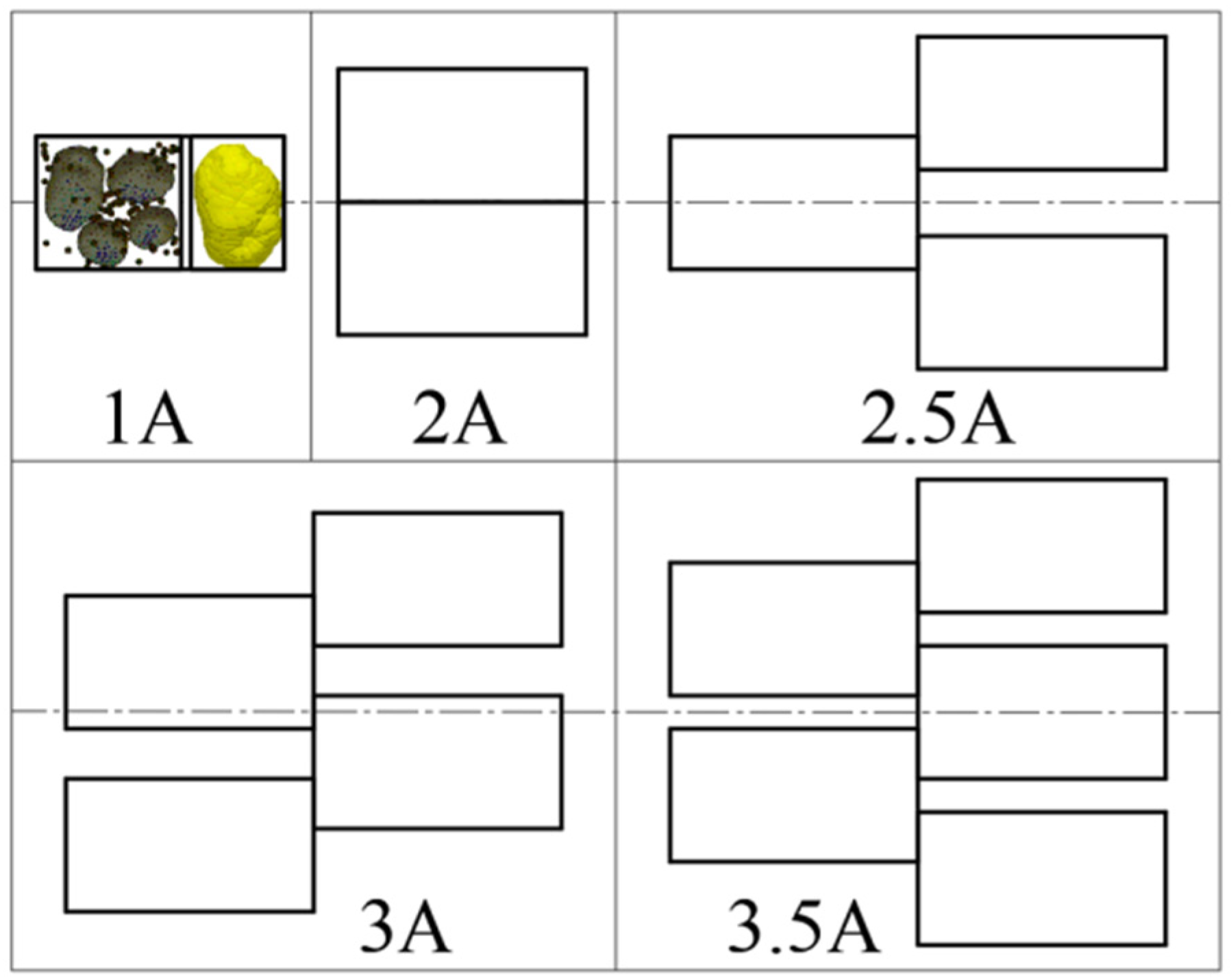
2.2.3. Establishment of Potato–Soil Aggregate Model

Prior to commencing the formal simulation experiments, it was crucial to formulate the model for potato–soil aggregates. Using the position coordinates derived from the preprocessing, soil particles were substituted, encompassing particle representations and bonding interactions, depicted in Figure 5 [28].

2.2.4. Establishment of Potato Excavator Separation Sieve Model

Using SOLIDWORKS 2018 software, a three-dimensional model of the swing separation sieve was crafted, accompanied by a simplified schematic diagram (depicted in Figure 2). Throughout the simulation, solely the structural motion characteristics and patterns were analyzed, while aspects regarding structural fatigue and reliability were not taken into account. Hence, SOLIDWORKS software was employed to streamline the structure, preserving the local motion effects without alteration, thereby embracing a more simplified design approach. Afterward, the streamlined separation sieve structure was imported into ADAMS 2018 software. Additionally, a “GFORCE” was integrated into each component to capture the forces applied by EDEM. The Adams Solver Dataset (*.adm) data file was exported, and environmental configurations were incorporated into it. Each component’s *.xt files were imported into EDEM using the coordinate information, and specific custom material properties were integrated, maintaining consistency with the properties configured in Adams. The detailed material parameters are outlined in Table 3.

2.3. Simulation Experiment on Potato–Soil Aggregate Breakup and Separation

2.3.1. Experimental Equipment and Factor Levels

Theoretical analysis of separation sieve acceleration (Section 2.1.2) and production experience indicated that the potato–soil separation effect and the performance of the swing separating sieve were primarily influenced by parameters such as crank radius, crank speed, sieve surface inclination angle, and machine forward speed [29]. By eliminating fixed and minor factors, the primary factors were selected for simulation experiments. The sieve surface inclination angle, crank speed, and machine forward speed were chosen as the experimental factors. Single-factor experiments were conducted to analyze the influence of each factor on potato motion, potato–soil aggregate separation, and the forces acting on the potatoes during the separation process. According to Table 1, the crank radius was fixed at 35 mm. Based on relevant literature [25,30] and theoretical analysis, the crank speed was set between 140 r/min and 220 r/min, the sieve surface inclination angle was set between 0.5° and 21.1°, and the machine forward speed was set between 0.63 km/h and 2.75 km/h. The factor levels for the simulation experiment are shown in Table 4.
The simulation experiment focused on evaluating the impact of specific factors: sieve inclination angle, crank speed, and machine forward speed. Each factor was individually tested to assess its influence on various aspects: potato movement, separation of potato–soil aggregates, and the force applied to the potato during the separation process.
From the preliminary field experiment, it was evident that increased machine forward speed resulted in a more substantial accumulation of potato–soil aggregates on the separation sieve. In order to replicate real field conditions, the thickness of potato–soil aggregates was adjusted relative to the machine’s forward speed. The amalgamation of the field experiment outcomes revealed that at a machine forward speed of 1.41 km/h, the potato–soil aggregate thickness measured 120 mm; at 1.71 km/h, it increased to 145 mm; and at 2.21 km/h, it further rose to 180 mm (illustrated in Figure 6).
Subsequently, a series of potato–soil aggregate heights, each measuring 63 mm [26,31], was established. These aggregates were categorized as 1A, 2A, 2.5A, 3A, and 3.5A based on their cumulative thickness (as depicted in Figure 7). Specifically, the corresponding machine forward speeds for 1A, 2A, 2.5A, 3A, and 3.5A were determined as 0.63 km/h, 1.47 km/h, 1.90 km/h, 2.32 km/h, and 2.75 km/h, respectively.

2.3.2. Experimental Indicators

  • The proportion of bonding bond fracture
The fragmentation and separation of potato–soil aggregates primarily occurred due to the breaking of bonds between soil particles and between soil particles and potatoes. Consequently, the ratio of bond fractures determined the extent of soil fragmentation and the level of potato–soil separation. The formula for its calculation is provided below.
p = n B n T × 100 %
In the formula, variables are defined as follows: p —Bonding bond fracture ratio. n B —Number of bonding bonds that fracture at the moment when all particles leave the sieve surface. n T —Total number of bonding bonds.
2.
Peak force on the potato
During the potato–soil separation, preserving the potatoes’ integrity was vital. Enhancing the efficiency of this process and minimizing soil fragmentation were essential goals, necessitating the reduction of impact force between the potatoes and the sieve bars to prevent skin cracking or any harm to the potatoes [32]. As per referenced literature [33], potato damage was initiated once the collision stress on the potatoes reached 0.2 MPa. During collisions with rubber-coated 65Mn steel and soil blocks, the potatoes achieved a maximum contact area of 700 mm2. Considering the contact area of 700 mm2 for force-stress calculations, the critical force causing potato damage was established at 140 N.
Consequently, the collision force impacting the potatoes was monitored continuously throughout the potato–soil separation process to assess any potential damage to the potatoes. These data were instrumental in deriving an optimal configuration for the swinging separation sieve structure and its operational parameters.

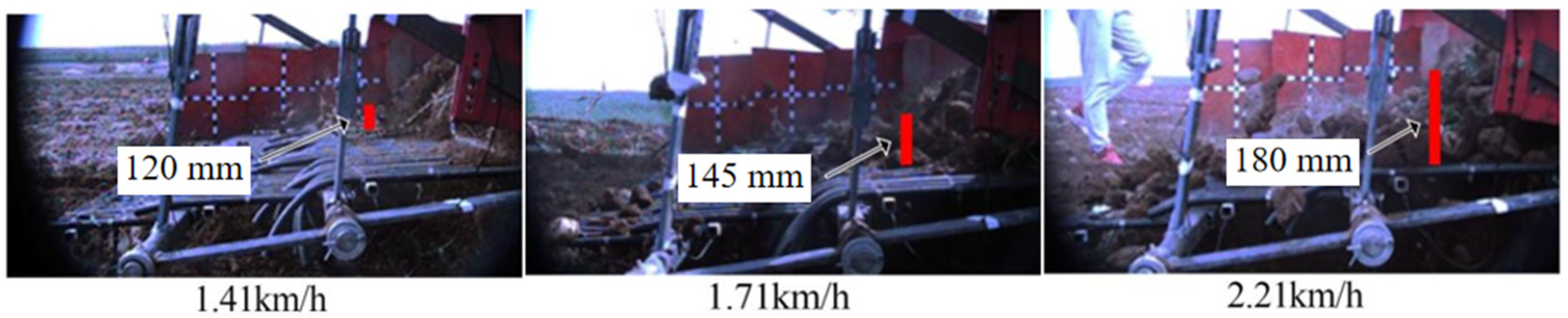
2.4. Field Validation Experiment

The field validation experiment was carried out at a potato planting base in Wuchuan County, Hohhot City, Inner Mongolia Autonomous Region, China. The experimental field features a flat terrain with sandy loam soil, and the selected potato variety was Jizhang Potato No. 12. The row spacing is set at 80 cm, and plant spacing varies between 20 cm and 35 cm.
The field validation experiment employed a 4SW-170 potato digger (Inner Mongolia Agricultural University Machinery Manufacturing Plant, Hohhot, China) fitted with an innovative swing separation sieve as the testing apparatus. The power was supplied by a Dongfeng DF900 tractor (Changzhou Dongfeng Agricultural Machinery Group Co., Ltd., Weihai, China). The digger’s crank speed is configured at 180 r/min, and the forward speed is established at 1.9 km/h. The inclination of the separation sieve is fixed at 14.4°.
The assessment criteria for the field validation experiment encompassed the potato detection rate and the potato skin breakage rate of the harvested potatoes. Following each set of tests, the recorded data included the total weight of potatoes fully exposed on the ground, the weight of potatoes with more than 1/4 of their surface exposed, and the weight of potatoes with skin damage. Subsequently, these data were employed to compute the potato detection rate ( Y 1 ) and the potato skin breakage rate ( Y 2 ) using the formulas presented below, in accordance with the guidelines stipulated in the “NY/T648-2015 Technical Specification for Quality Evaluation of Potato Harvesters” [34].
Y 1 = q 1 Q × 100 % Y 2 = q 2 Q × 100 %
  • q 1 : Weight of potatoes fully exposed on the ground after machine operation (kg).
  • q 2 : Weight of potatoes with skin damage after machine operation (kg).
  • Q : Total weight of harvested potatoes after machine operation (kg).

3. Results and Discussion

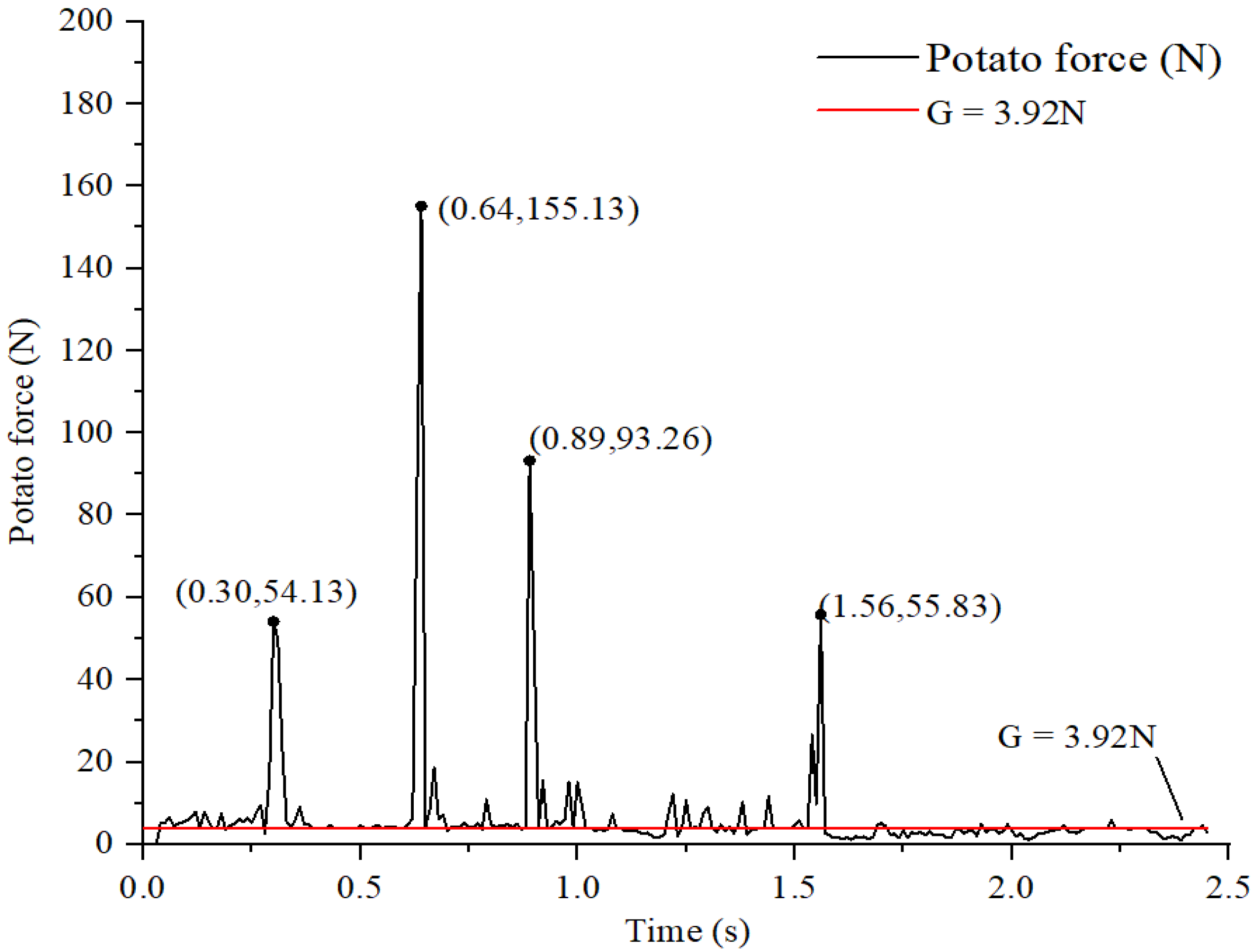
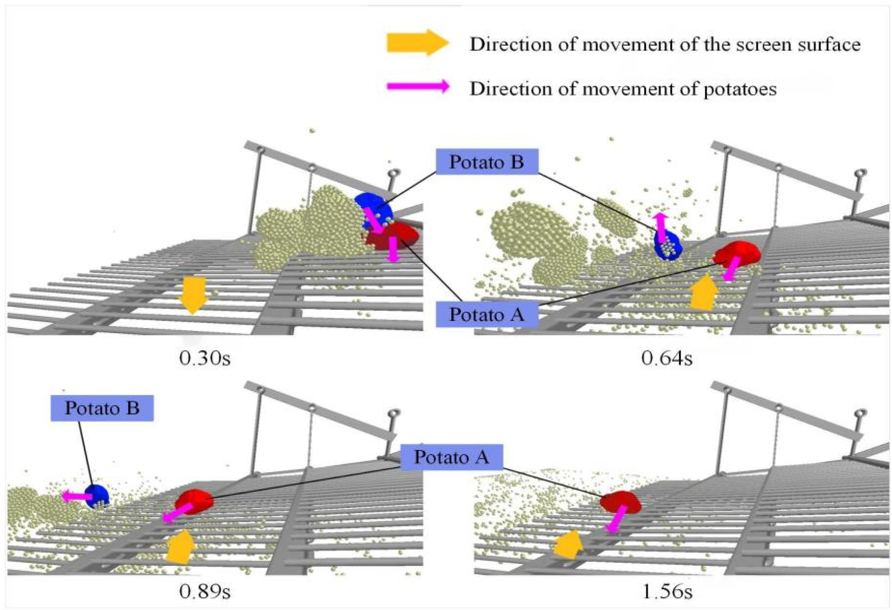
3.1. Analysis of Potato Force Process

As potatoes descend onto the sieve surface, they undergo continuous collisions with both the soil particles and the sieve bars. If multiple potatoes are present, collisions among the potatoes themselves may also take place. Figure 8 and Figure 9 provide visual representations detailing both the force applied to the potatoes throughout the collision process and the collision dynamics themselves.
Examination of Figure 8 and Figure 9 reveals that in the absence of collision with any object, the force applied to the potato remains relatively constant, corresponding to the potato’s weight of 3.92 N. At 0.30 s, upon the descent of potato B, a collision occurs with potato A, resulting in the force reaching its initial peak. During this collision, potato A experiences the simultaneous collision force from both potato B and the sieve bar. At 0.64 s, as potato A descends onto the second layer of the sieve surface and the surface begins to move upward, there is a notably high relative velocity between the potato and the sieve surface, consequently leading to the occurrence of the maximum peak force. At 0.89 s, as potato A approaches the terminus of the second layer of the sieve surface, it experiences forces from both the end of the second layer and the base of the third layer, culminating in the occurrence of the third peak force. By 1.56 s, as potato A descends onto the third layer of the sieve surface and the surface ascends, the collision between the potato and the moving sieve surface generates the ultimate peak force due to their maximum relative velocity.
Through analyzing the collision process of potatoes under various experimental conditions, it is evident that all the corresponding peak points result from collisions between the potatoes and the sieve bars.

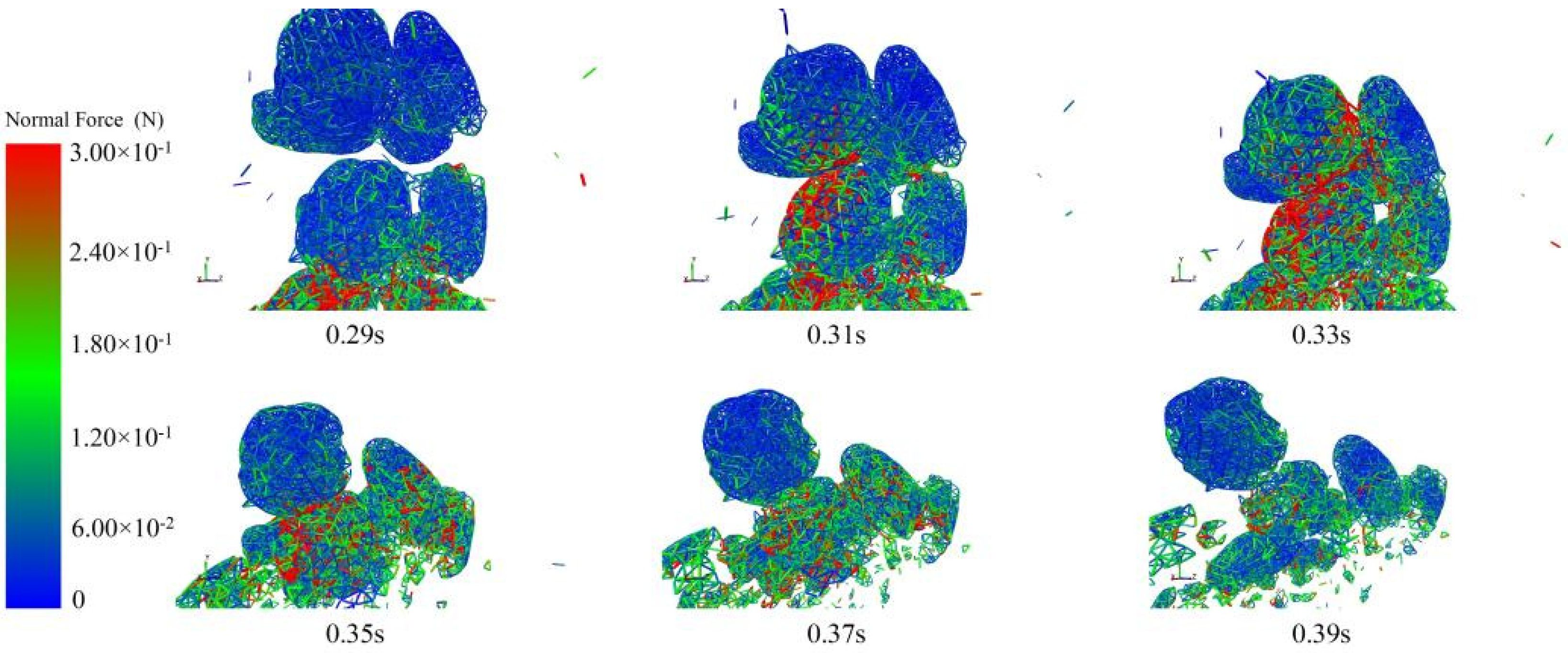
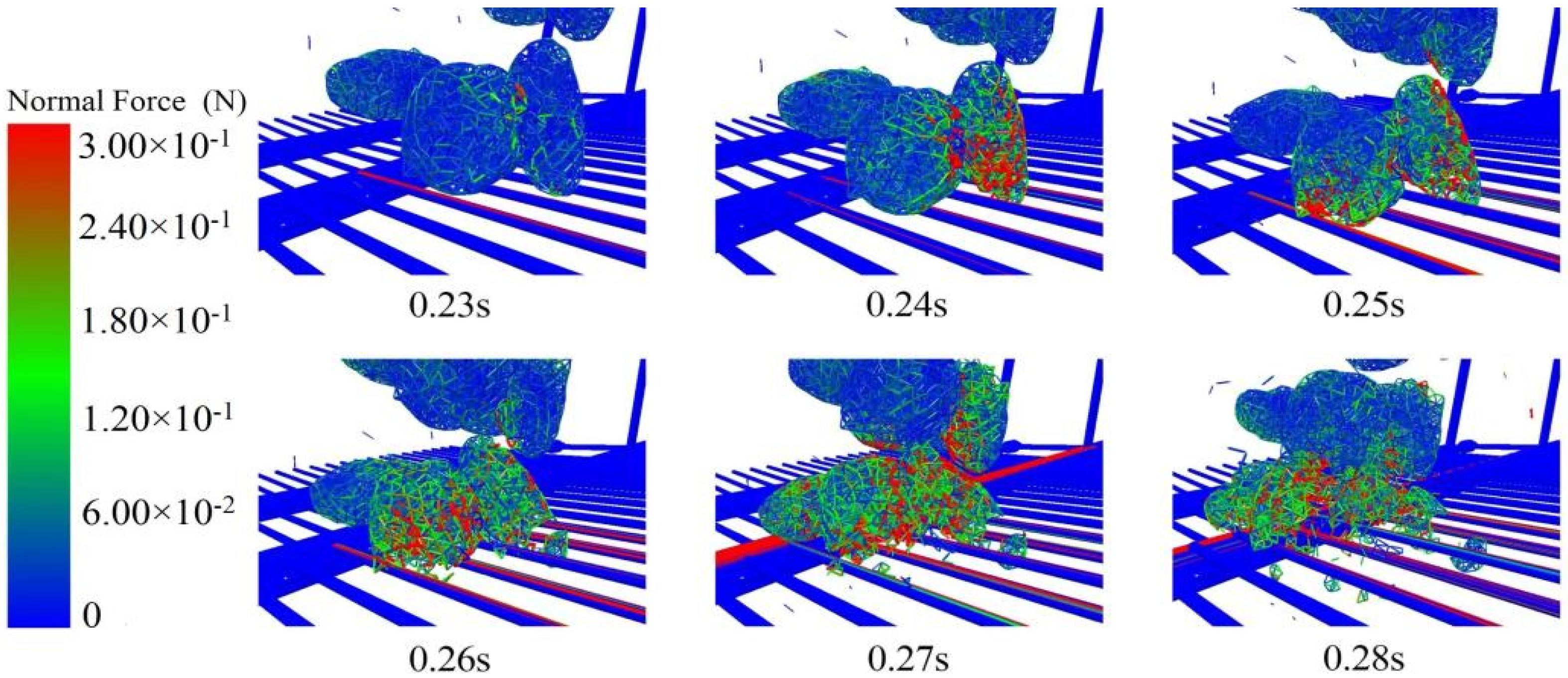
3.2. Analysis of Potato-Soil Aggregate Bonding Bond Fracture Process

In the simulation experiment, bonds form concurrently between the potatoes and the soil and among soil particles. Soil aggregates begin by dropping from the particle factory onto the separating sieve surface, gradually fracturing under the sieve’s swinging motion. This entire process encompasses interactions: collisions among soil particles, between potatoes and soil, and between soil and the sieve surface. Due to the limited number of potatoes, the analysis focuses solely on collisions among soil particles and between soil and sieve bars. In the examination of the bonds between potatoes and soil, two scenarios are considered: one where potatoes collide with the sieve bars initially and another where soil particles make initial contact with the sieve bars.

3.2.1. Analysis of the Force on the Soil-Soil Bonding Bonds during Soil-to-Soil Collisions

In this analysis, the soil is treated as a viscoelastic substance, resulting in a complex and variable collision process between soil particles. For the sake of analytical convenience, the collision process of two typical soil aggregates along the normal direction is specifically investigated, as illustrated in Figure 10.
The point of contact between two soil blocks initiates a gradual increment in the force exerted on the bonding bonds, notably expanding along the gravitational direction as they join together. As soil particles collide, deformation occurs, leading to the gradual compression of the soil toward its core, distributing stress throughout the soil block. Upon reaching its deformation limit, the soil surface, facing impacts from both sides, begins disintegrating until stress levels retreat to tolerable extents, halting the fracturing of bonding bonds. Conversely, with a one-sided collision, minimal fragmentation ensues, followed by soil restoration to its original form.

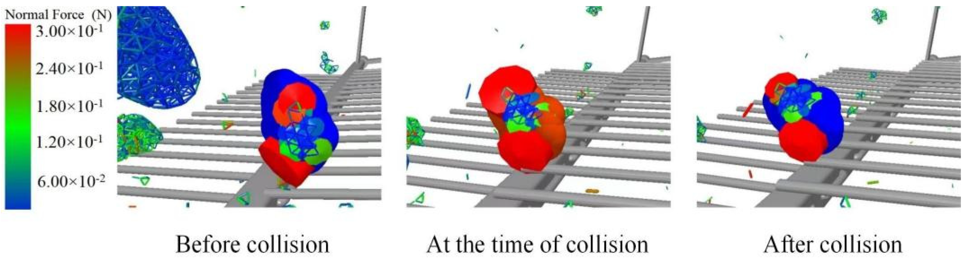
3.2.2. Analysis of the Force on the Soil-Soil Bonding Bonds during Soil-Sieve Bar Collisions

The relative velocity between the soil and the sieve bar remains unpredictable during their collision, owing to the motion of the sieve bar. Nonetheless, a consistent soil fragmentation pattern emerges. The collision between the soil and the sieve bar can be classified into two categories, as depicted in Figure 11: (1) direct collision of soil with a single sieve bar and (2) soil positioned between two sieve bars, simultaneously colliding with both.
At 0.24 s, the soil undergoes a direct collision with a single sieve bar. Analysis of the figure reveals a force distribution pattern on the bonding bonds resembling the collision between soil particles. This distribution spans from a single point across the entire soil, causing compression until it approaches its limit, subsequently resulting in fractures, ultimately leading to soil disintegration from the surface.
At 0.26 s, another section of soil descends between the two sieve bars. The figure illustrates a force distribution pattern on the bonding bonds located on either side of the soil, extending outward from two distinct points. In contrast to the direct collision with a single sieve bar, the bonding bonds of the soil encounter more prominent fractures in this scenario.

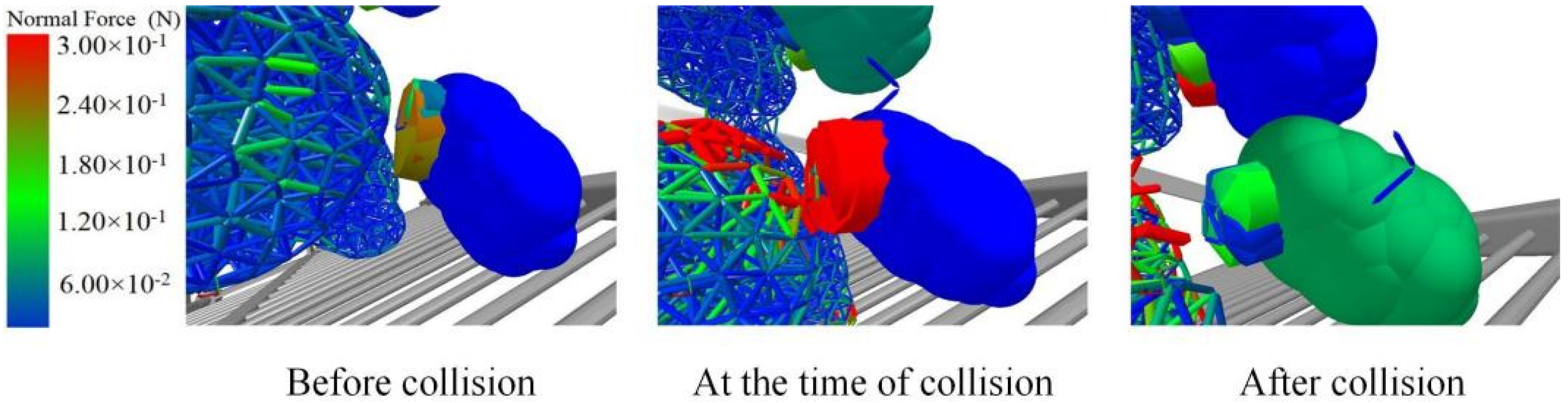
3.2.3. Analysis of the Force on the Potato–Soil Bonding Bonds when the Potato Collides with the Sieve Bar First

The primary force responsible for fracturing the bonding bonds between the potato and soil originates mainly from the collisions between the potato–soil aggregates and the sieve bar. If the collisions were solely among the materials, the collective force on the bonding bonds of the potato–soil aggregate would not suffice to induce their breakage. During the simulation process, multiple observations revealed that the collisions between the potato–soil aggregates and the sieve bar can be categorized into two types: collisions initiated by the potato’s impact with the sieve bar and those instigated by the soil’s collision with the sieve bar. It is highly improbable for both the potato and soil from the same set of potato–soil aggregates to simultaneously collide with the sieve bar.
Illustrated in Figure 12 is the collision process when the potato initiates contact with the sieve bar. The visualization reveals that before the collision, the bonding bonds between the potato and soil maintain a considerable distance from the sieve bar. During this phase, the potato exhibits both translational and rotational movements. The soil particles affixed to the potato encounter persistent, dynamically shifting forces owing to inertia, creating challenges for the fracture of the bonding bonds between the potato and soil.
Throughout the collision, the direction of the potato’s velocity alters due to the force applied by the sieve bar, instigating vigorous micro-level vibrations within the soil particles. Outer soil particles exhibit fewer bonding bonds in contrast to those closer to the center. Consequently, when subjected to similar vibrations, the outer soil’s bonding bonds endure heightened force and possess a greater susceptibility to fracture. Upon reaching the critical fracture threshold, the soil particles disengage from the potato. Following the collision, certain soil particles fail to revert to their pre-collision state.

3.2.4. Analysis of the Force on the Potato-Soil Bonding Bonds when the Soil Collides with the Sieve Bar First

When the soil encounters the sieve bar initially, as depicted in Figure 13, the right figure indicates that preceding the collision, the bonding bonds within the soil remain subjected to minimal force. However, owing to the substantial mass of the soil block, it undergoes substantial gravitational force, leading to comparatively elevated pressures on the bonding bonds between the potato and soil. Nonetheless, these forces fail to meet the necessary conditions for fracture.
As the soil block collides with the sieve bar, its velocity rapidly diminishes until it becomes 0 m/s. However, owing to its larger mass and inertia, the potato persists in descending due to inertia. Following the collision, the forces acting on the bonding bonds between the potato and soil undergo a sudden increase, leading to the rupture of these bonds. Consequently, this causes a distinct separation between the potato and the soil at a visible scale.
Following the collision, the soil block and the potato are fully disentangled; however, traces of soil particles persist on the potato’s surface. Successive collisions fail to entirely disengage them from the potato, illustrating the common occurrence in practical scenarios where a minor amount of soil lingers attached to the potato’s surface post-sieving.

3.3. Influence of Experimental Factors on Bonding Bond Fracture

3.3.1. The Influence of Crank Speed on the Bonding Bond Fracture

When the machine’s forward speed is set at 1.9 km/h, and the sieve inclination angle stands at 7.7°, EDEM simulations were performed to evaluate five crank speeds: 140 r/min, 160 r/min, 180 r/min, 200 r/min, and 220 r/min. Each condition underwent three repetitions, and the average results from these three trials were computed. Table 5, provided below, presents the count of created and fractured bonding bonds alongside the fracture ratio corresponding to each crank speed.
From Table 5, it is evident that the fracture ratio of the soil–soil bonding bonds escalates with the increasing crank speed. Within the range of 140 r/min to 160 r/min, this ratio remains below 65%. At a macroscopic level, the soil retains its aggregated state, making it challenging to dislodge from the gaps between the sieve bars, consequently affecting the marketable potato yield due to buried potatoes. As the crank speed hits 180 r/min, the fracture ratio of the bonding bonds peaks at 69.66%. Analysis of soil fragmentation during the simulation process reveals that a fracture ratio of 65% in internal soil bonding bonds signifies a relatively high level of soil fragmentation, allowing most of the soil to dislodge from the sieve bars’ gaps.
Through linear fitting analysis of the curve, the derived fitting equation is
y = 0.002 x + 0.3   ( R 2 = 0.989 )
Solving the fitted equation reveals that at a fracture ratio of 65% for the bonding bonds, the corresponding crank speed is 170 r/min. Hence, if the crank speed exceeds 170 r/min, the level of soil fragmentation satisfies the specified criteria.
Table 5 indicates that the overall fracture ratio of the bonding bonds between the potato and soil in the process of potato–soil aggregates’ fragmentation and separation is insignificant. This phenomenon arises as the bonding bonds within the potato–soil aggregates tend to initiate fractures from the interior of the soil upon experiencing external collisions. Despite the separation of the soil and potato, a few soil particles persist on the surface of the potato. The bonding bonds between these soil particles and the potato are resistant to disruption by external forces.
The peak fracture ratio of the bonding bonds between the potato and soil occurs at crank speeds of 160 r/min and 180 r/min, while the lowest ratios are observed at crank speeds of 140 r/min and 200 r/min. Through data fitting for the soil–potato bonding bonds, the resulting equation is
y = 9.02 × 1 0 7 x 3 5.06 × 10 4 x 2 + 0.93 x 5.37   ( R 2 = 0.861 )
After solving the polynomial equation and considering the internal soil bonding bond fracture pattern, it is concluded that the crank speed leading to the highest overall fracture degree for both types of bonding bonds is approximately 180 r/min. This speed results in the most pronounced separation between the potato and soil, maximizing soil fragmentation.

3.3.2. The Influence of Machine Forward Speed on the Bonding Bond Fracture Situation

EDEM simulations were executed at a sieve inclination angle of 7.7° and a crank speed of 180 r/min under five machine forward speed conditions: 0.63 km/h, 1.47 km/h, 1.9 km/h, 2.32 km/h, and 2.75 km/h. Each scenario underwent three repetitions, and the results were averaged across the trials. Table 6 presents the counts of generated and fractured bonding bonds, along with the fracture ratio, corresponding to each machine forward speed condition.
Examining Table 6 reveals that within the machine forward speed range of 0.63 km/h to 2.75 km/h, the fracture ratio of the bonding bonds within the soil consistently exceeds 65%, satisfying the criteria for effective soil fragmentation. Specifically, at a machine forward speed of 0.63 km/h, all soil blocks descend directly, engaging with the sieve bars. During the subsequent sieving process, these blocks undergo repeated collisions with the bars, leading to the highest fracture ratio of the bonding bonds within the soil and, consequently, the most extensive soil fragmentation.
Nonetheless, with an increase in machine forward speed, resulting in a higher number of potato–soil aggregates, only the initial group falls directly onto the sieve surface. Subsequent aggregates descend onto the preceding layer of soil. In contrast to a direct collision with the sieve surface, this arrangement significantly diminishes the force on the bonding bonds, resulting in a decreased degree of soil fragmentation.
Employing polynomial fitting on the data yields the fitting equation:
y = 0.08 x 3 + 0.45 x 2 0.81 x + 1.13   ( R 2 = 0.963 )  
Solving this equation reveals that, for all five scenarios, the fracture ratio of the bonding bonds exceeds 65%, satisfying the specified requirement.
As indicated by Table 6, at a machine forward speed of 0.63 km/h, the fracture ratio of bonding bonds between potatoes and soil is comparatively low. This phenomenon arises due to the lower number of potato–soil aggregates at this speed, resulting in rapid breakage of the bonding bonds among the soil particles. Consequently, a minor fraction of soil particles persists on the surface of the potatoes. These soil particles are relatively lightweight, posing challenges in their removal from the potato surface through vibration.
In the range of machine forward speeds from 1.47 km/h to 1.9 km/h, there is an increased presence of soil and potato aggregates. The interplay of friction between potatoes and soil, coupled with the vibration of the sieve, facilitates the rapid detachment of soil particles from the surface of the potatoes.
In the machine forward speed range of 2.32 km/h to 2.75 km/h, the quantity of soil aggregates peaks. During this phase, the potato–soil aggregates landing on the sieve experience minimal impact from the sieve’s vibration, resulting in the removal of only a small amount of soil from the potato surface. Consequently, the bonding bond fracture ratio between potatoes and soil undergoes a significant decrease.
Through polynomial fitting of the data, the resulting fitted equation is
y = 0.06 x 3 + 0.39 x 2 0.69 x 0.11   ( R 2 = 0.833 )
Upon solving the polynomial equation, it is established that within the machine forward speed range of 1.47 km/h to 1.9 km/h, the bonding bond fracture ratio for both potato–soil and soil–soil scenarios surpasses the stipulated requirement of being greater than 65%.

3.3.3. Influence of Sieve Inclination on Bonding Key Fracture

Under the conditions of a machine forward speed set at 1.9 km/h and a crank speed of 180 r/min, we performed EDEM simulations for four distinct sieve inclinations (0.5°, 7.7°, 14.4°, and 21.1°). Each configuration underwent three repeated trials for experimental analysis, and the conclusive results were derived from averaging the outcomes of these three trials. The data detailing the quantities of generated and fractured bonding keys, alongside the respective fracture ratios, are outlined in Table 7.
Examining Table 7 reveals that with an increase in sieve inclination, the soil motion demonstrates larger fluctuations but with fewer oscillations [25], resulting in a gradual reduction in the internal bonding key fracture ratio. Specifically, when the sieve inclination is 0.5°, approaching parallel alignment with the ground, the soil exhibits the highest bonding key fracture ratio. However, at this angle, the transportation of potatoes to the end of the separation sieve becomes challenging, leading to repeated bouncing on the sieve surface. With a sieve inclination of 7.7°, potato–soil aggregates undergo 1–2 jumps on each sieve level, yielding a bonding key fracture ratio of 76.62%, signifying ample soil fragmentation and compliance with the requirements for soil breakdown. With the sieve inclination reaching 14.4°, a majority of potato–soil aggregates directly descend to the third sieve level, causing a limited impact on the soil and resulting in a diminished level of soil fragmentation. At a sieve inclination of 21.1°, potato–soil aggregates experience only 1–2 impacts throughout the process, leading to fewer bonding key fractures and a low fracture ratio, indicative of inadequate soil fragmentation. The linear fitting of the data produces the following equation:
y = 0.018 x + 0.845   ( R 2 = 0.974 )
Solving this equation reveals that when the sieve inclination is less than 11°, the internal bonding key fracture level within the soil exceeds 65%, satisfying the criteria for soil fragmentation.
Analyzing Table 7 reveals a clear trend of decreasing bonding key fracture ratio between potatoes and soil with an increase in the sieve inclination angle. At a 0.5° sieve inclination, the bonding key fracture level peaks at 42.7%. For sieve inclinations of 7.7° and 14.4°, the bonding key fracture ratio remains relatively constant at approximately 25%. Upon reaching a sieve inclination of 21.1°, the fracture ratio reaches its minimum at 16.09%. Employing a linear equation to fit the data produces the following equation:
y = 0.01 x + 0.4   ( R 2 = 0.848 )
Solving this fitting equation indicates that the optimal condition for effective potato–soil separation occurs when the sieve inclination is less than 11°.

3.4. The Influence of Experimental Factors on Potato Force Situation

3.4.1. The Influence of Crank Speed on Potato Force Situation

The analysis of potato force was conducted under various crank speed conditions, and the recorded peak force values were examined to discern the potato force pattern. The findings are detailed in Table 8. It is noted that with an escalation in crank speed, the peak force encountered by the potatoes exhibits a linear increase. Upon reaching a crank speed of 200 r/min, the peak force attains 196.6 N, corresponding to a contact stress of approximately 0.281 MPa, surpassing the critical damage stress of potatoes by 1.4 times. At a crank speed of 180 r/min, the potato force registers at 149.13 N, and the associated contact stress is around 0.213 MPa. The linear fitting of the data yields the following equation:
y = 2.6 x 317.05   ( R 2 = 0.976 )
Upon resolving the fitting equation, it is determined that when the stress is 0.2 MPa, the corresponding crank speed is approximately 175 r/min. Taking into account all the aforementioned factors and the compatibility between the tractor’s forward gear and speed, a crank speed of 180 r/min is selected as the practical field operation parameter.

3.4.2. Effect of Machine Forward Speed on Potato Force Situation

In the examination of diverse machine forward speed conditions, the analysis and recording of peak potato force were conducted, presenting the observed pattern in Table 9. Analysis of Table 9 reveals a decrement in the peak force of potatoes with an escalation in machine forward speed. At a machine forward speed of 0.63 km/h, the peak force of potatoes reaches 348 N, accompanied by a contact stress of approximately 0.497 MPa. With a machine forward speed of 1.47 km/h, the force peak measures 202.63 N, with a contact stress of approximately 0.289 MPa, surpassing the critical stress for potato damage by approximately 1.5 times. Within the machine forward speed range of 1.9 to 2.32 km/h, the declining force trend moderates, stabilizing around 145 N, with a contact stress of 0.207 MPa, satisfying the criteria for potato damage. The data were fitted using a polynomial equation:
y = 96 x 3 + 547 x 2 1038 x + 808   ( R 2 = 0.999 )
Upon resolving the fitted equation, it is determined that a machine forward speed greater than 1.9 km/h satisfies the requirement for potato damage. Taking into account the bonding key fracture conditions, a machine forward speed of 1.9 km/h is chosen as the operational speed for the field experiment.

3.4.3. The Effect of Sieve Surface Inclination on Potato Force Situation

The forces acting on the potatoes were analyzed at different sieve surface inclination angles, and the peak force points were recorded to determine the force patterns on the potatoes, as shown in Table 10. Table 10 shows that as the sieve surface inclination increases, the force on the potatoes first decreases, then increases, and finally decreases again, with the peak force being somewhat random. The peak forces are relatively random. The linear fitting of the data yields the following equation:
y = 9.22 x 237.22   ( R 2 = 0.449 )
Taking into account the criteria for bonding key fracture and the adjustable range of the sieve surface angle, a sieve surface inclination of 14.4°is chosen as the operational parameter for the potato digger.

3.5. Variance Analysis of Proportion of Bonding Bond Fracture and Peak Force on Potato under Different Levels of Experimental Factors

To clarify the significant differences between the levels for the proportion of bonding bonds broken between soil and soil, soil and potato, and the peak stress in potato under different test factors, using SPSS 26 software, the test results obtained at each level under different test factors were first tested for S-W normal distribution. The results showed that the test data obtained under the conditions of different machine forward speeds, different sieve inclination angles, and different crank speeds all conformed to a normal distribution, so the results of the one-factor test were analyzed by analysis of variance (ANOVA), and the results are shown in Table 11.
Table 11 shows that the sieve surface inclination angle has a highly significant effect (p < 0.01) on the bonding bond fracture ratio between soil particles and the peak forces on the potatoes. t also significantly affects (p < 0.05) the bonding bond fracture ratio between soil particles and potatoes. Although the previous section mentioned that the influence of the sieve surface inclination angle on the peak forces on potatoes is relatively random, it still has a significant impact. This indicates that the sieve surface inclination angle is an important factor affecting these indicators.
The machine forward speed has a significant effect (p < 0.05) on all three experimental indicators, with a highly significant impact (p < 0.01) on the peak forces on potatoes. This indicates that altering the machine forward speed can significantly change the experimental results, making it a key parameter for optimizing experimental conditions.
The crank speed has a highly significant effect (p < 0.01) on the bonding bond fracture ratio between soil particles and the peak forces on potatoes and a significant effect (p < 0.05) on the bonding bond fracture ratio between soil particles and potatoes. This indicates that crank speed is also an important factor affecting the experimental results.
As shown in Table 11, the p-value for the sieve surface inclination angle, machine forward speed, and crank rotation speed across different test indicators is less than 0.05. This indicates significant differences between the levels of these factors. To further elucidate which specific levels of different factors contribute to these significant differences in the mean values of the test indicators, Duncan’s test was conducted on the single-factor test data. The results of this test are presented in Table 5, Table 6, Table 7, Table 8, Table 9 and Table 10.

3.6. Analysis of Significant Differences between Interactions of Different Test Factors for Test Indicators

From the one-way ANOVA in Section 3.5, it can be concluded that the effects of the three factors—sieve inclination angle, machine forward speed, and crank speed—on the test metrics were all significant. To clarify the significant differences in the interaction of different test factors on the bonding bond breaking ratio between soil and soil, soil and potato, and the peak stress of potatoes, a multiple comparative analysis (LSD) was conducted. This analysis assessed the effects of interactions between different factors on the test indexes. The results of the multiple comparative analysis (LSD) are presented in Table 12.
The LSD analysis showed that the effects of the factors and their interactions on the bonding bond ratios between soil and soil, soil and potato, and on the peak stress of potatoes were not significant (p > 0.05). This indicates that, under the same test conditions, the interaction between different factors does not significantly affect the test indexes.

3.7. Results and Analysis of Field Validation Tests

Based on the analysis of the results from multiple comparisons using the LSD method in Section 3.6, it was found that the interactions between the different test factors did not significantly affect the test metrics. Consequently, in this study, the bonding bond fracture ratio rupture data under each independent factor were linearly fitted, and the fitted equations were solved to determine the range of optimal structural parameter combinations. To further narrow down the parameter range and identify a unique solution for the optimal structural parameter combination, the peak force of the potato under different test factors was analyzed. By integrating relevant references [26], the laws and conclusions from single-factor tests, and comprehensively considering multiple factors, the optimal structural parameter combination for the new swing separating sieve was determined. The final parameters were set as a crank rotation speed of 180 r/min, a machine forward speed of 1.9 km/h, and a sieve surface inclination angle of 14.4°. Field validation tests were then conducted based on this optimal structural parameter set. The results of these field tests are presented in Table 13.
The results of the field test are shown in Table 12. With the optimal parameter combination of a crank speed of 180 r/min, a machine forward speed of 1.9 km/h, and a sieve surface inclination angle of 14.4°, the potato detection rate is 98.01%, and the skin-breaking rate is 0.68%. These values exceed the technical requirements of the “Technical Specification for Quality Evaluation of Potato Harvester” (NY/T648-2015), which specify a potato detection rate of 98% and a skin-breaking rate of 2%. It was also better than the results of 98.04% and 1.58% of detection potato and skin-breaking rate, respectively, obtained from the validation test conducted by Xie et al. [26] with the structural parameter combinations of crank speed of 180 r/min, machine forward speed of 1.89 km/h, and suspension-connecting rod length combinations of 270-370-1050.
Therefore, the optimal separation sieve structural parameters not only comply with the relevant standards but also further validate the accuracy of the optimal structural parameters selected through the simulated one-factor test.

4. Conclusions

Based on the new swing separation sieve acceleration theory analysis and related literature, we designed the basic structural dimensions as follows: The crank radius is 35 mm, the crank connecting rod length is 1050 mm, the length of the connecting rod between the first- and second-order sieve surfaces is 370 mm, the length of the connecting rod between the second- and third-order sieve surfaces is 270 mm, the length of the first-order sieve surface is 400 mm, the lengths of the second- and third-order sieve surfaces are 300 mm each, the length of the first-order sieve surface suspension rod is 270 mm, the length of the second-order sieve surface suspension rod is 370 mm, the length of the third-order sieve surface suspension rod is 570 mm, the total length of the sieve surface is 1000 mm, and the width of the sieve surface is 1700 mm.
The fracture behavior of soil–soil and potato–soil bonding bonds under different test factors was investigated. It was found that the fracture proportion of soil–soil bonds increased with crank speed and decreased with sieve inclination angle, while the fracture proportion of potato–soil bonds decreased with sieve inclination angle. The maximum fracture degree for both potato–soil and soil–soil bonds was observed at a crank speed of 180 r/min and a machine forward speed of 1.9 km/h. One-way analysis of variance (ANOVA) indicated that sieve surface inclination, machine forward speed, and crank speed significantly affected the fracture of bonding bonds.
The peak force on potatoes was investigated under different test conditions. It was found that the peak force increased with crank speed and decreased with machine forward speed. The influence of sieve surface inclination on the force exerted on potatoes was relatively random, with peak forces at different angles remaining below the critical value of 200 N. One-way ANOVA revealed that crank speed, machine forward speed, and sieve surface inclination significantly affected the peak force on potatoes.
In the field validation experiment, the selected parameters included a crank speed of 180 r/min, a machine forward speed of 1.9 km/h, and a sieve surface inclination of 14.4°. The outcomes indicated that under these specified conditions, the average intact potato rate achieved 98.01%, with a minimal skin damage rate of only 0.68%, aligning with the stipulations of the potato harvesting machinery technical specification.

Author Contributions

S.X.: Conceptualization, Methodology, Visualization, Supervision, and Funding Acquisition; Y.Z.: Data Curation, Writing—Original Draft Preparation, and Software; J.L.: Validation, Investigation, and Software; F.L.: Data Curation. All authors have read and agreed to the published version of the manuscript.

Funding

This work was supported by the Interdisciplinary Research Fund of Inner Mongolia Agricultural University (BR231505), the National Natural Science Fund of China (31901409), the Natural Science Foundation of Inner Mongolia Autonomous Region of China (2022MS05027), the Inner Mongolia Autonomous Region Graduate Research Innovation Project (S20231118Z), the Open Research Platform Project of Xihua University (XDNY2023-006), the Inner Mongolia Agricultural University College Student Innovation and Entrepreneurship Training Program Project (202210129036), and the Science and Technology Program of Inner Mongolia Autonomous Region of China (2023YFHH0013) for developing the research.

Data Availability Statement

The original contributions presented in the study are included in the article, further inquiries can be directed to the corresponding author.

Conflicts of Interest

The authors declare that they have no known competing financial interests or personal relationships that could have appeared to influence the work reported in this paper.

References

  1. Yao, Y.; Yang, J.; Xiao, G.; Zhao, H.; Lei, J.; Niu, H.; Zhang, X. Progress and Prospect of Research on the Impact of Climate Warming on Potato Growth and Yield. Ecol. Environ. Sci. 2017, 26, 538–546. [Google Scholar] [CrossRef]
  2. Chen, H.; Liu, Q. The Research Progress and Prospect of Potato Peeling Technology. Food Ind. 2016, 37, 229–232. [Google Scholar]
  3. Li, Z.; Chang, Q.; Liu, J.; Dong, X. Development Status and Trend of Domestic and Overseas Potato Harvesters. Mod. Manuf. Technol. Equip. 2020, 56, 207–208. [Google Scholar] [CrossRef]
  4. Zhang, Y. Potato cultivation techniques in Suihua. Seed World 2014, 374, 39–40. [Google Scholar] [CrossRef]
  5. He, J. Status Quo and Suggestions of China’s Potato Industry Development. Agric. Outlook 2020, 16, 34–39. [Google Scholar] [CrossRef]
  6. Lv, J.; Tian, Z.; Yang, Y.; Shang, Q.; Wu, J.; Li, Z.; Wang, X. The Development Situation, Existing Problems and Development Trend of Potato Machinery. J. Agric. Mech. Res. 2015, 37, 258–263. [Google Scholar] [CrossRef]
  7. Lv, J.; Su, H.; Dui, H.; Peng, M.; Yu, J. Design and Experiment on Conveyor Separation Device of Potato Digger under Heavy Soil Condition. Trans. Chin. Soc. Agric. Mach. 2017, 48, 146–155. [Google Scholar] [CrossRef]
  8. Li, H.; Gao, F. Improvement Design of Separation and Conveying Machinery and Equipment of Potato Excavator in Heavy Soil. Phys. Chem. Earth Parts A/B/C 2023, 130, 103363. [Google Scholar] [CrossRef]
  9. Yang, F.; Sun, B.; Zheng, X.; Wei, H.; Chai, S. Research Status and Development Trend of Potato Harvesters. For. Mach. Woodwork. Equip. 2021, 49, 4–10. [Google Scholar] [CrossRef]
  10. Wang, S.; Gao, A.; Meng, Y. The current situation and development trend of potato harvesters. For. Mach. Woodwork. Equip. 2023, 51, 12–16. [Google Scholar] [CrossRef]
  11. Lv, J.; Tian, Z.; Yang, Y.; Shang, Q.; Wu, J. Design and experimental analysis of 4U2A type double-row potato digger. Trans. Chin. Soc. Agric. Eng. 2015, 31, 17–24. [Google Scholar] [CrossRef]
  12. Wei, Z.; Li, H.; Sun, C.; Li, X.; Liu, W.; Su, G.; Wang, F. Improvement of potato harvester with two segment of vibration and wave separation. Trans. Chin. Soc. Agric. Eng. 2018, 34, 42–52. [Google Scholar] [CrossRef]
  13. Wu, J.; Li, H.; Sun, W.; Huang, X.; Zhang, W. Experiment on poke finger wheel type potato digger. Trans. Chin. Soc. Agric. Eng. 2011, 27, 173–177. [Google Scholar] [CrossRef]
  14. Yang, R.; Yang, H.; Shang, S.; Xu, P.; Cui, G.; Liu, L. Design and Test of Poking Roller Shoving Type Potato Harvester. Trans. Chin. Soc. Agric. Mach. 2016, 47, 119–126. [Google Scholar] [CrossRef]
  15. Shi, L.; Wu, J.; Zhao, W.; Sun, W.; Wang, D.; Li, H.; Liu, Q. Design and experiment on potato digger of disc ce-grate type. Trans. Chin. Soc. Agric. Eng. 2012, 28, 15–21. [Google Scholar] [CrossRef]
  16. Zhang, H.; Wu, J.; Sun, W.; Luo, T.; Wang, D.; Zhang, J. The design and experiment of 4UM-640 vibration potato digger. Agric. Res. Arid Areas 2014, 32, 264–268. [Google Scholar]
  17. Feng, L. The Performance Study of the Potato Digger Sieve System. Master’s Thesis, Hebei Agricultural University, Baoding, China, July 2004. [Google Scholar]
  18. Zhao, M.; Zhao, S.; She, D.; Liu, H.; Liu, W.; Wang, Z. Combined separation type potato digger. J. Agric. Mech. Res. 2007, 4, 69–72. [Google Scholar] [CrossRef]
  19. Baritelle, A.L.; Hyde, G.M. Specific Gravity and Cultivar Effects on Potato Tuber Impact Sensitivity. Postharvest Biol. Technol. 2003, 29, 279–286. [Google Scholar] [CrossRef]
  20. Bentini, M.; Caprara, C.; Martelli, R. Harvesting Damage to Potato Tubers by Analysis of Impacts Recorded with an Instrumented Sphere. Biosyst. Eng. 2006, 94, 75–85. [Google Scholar] [CrossRef]
  21. Singh, R.D.; Singh, H.M. Comparative performance of potato digger elevator with conventional method of harvesting at farmer’s fields. Potato J. 2004, 31, 159–164. [Google Scholar] [CrossRef]
  22. Zhang, J.; Jin, L.; Xie, K.; Pang, W.; Bian, C.; Duan, S.; Qu, D. Comprehensive evaluation of potato bruises in different genotypes. Sci. Agric. Sin. 2009, 42, 198–203. [Google Scholar] [CrossRef]
  23. Opara, U.L.; Pathare, P.B. Bruise Damage Measurement and Analysis of Fresh Horticultural Produce—A Review. Postharvest Biol. Technol. 2014, 91, 9–24. [Google Scholar] [CrossRef]
  24. Yang, L. Simulation and Optimization on Parameters of Separation of Potato Digger. Master’s Thesis, Inner Mongolia Agricultural University, Hohhot, China, July 2009. [Google Scholar]
  25. Xie, S. Theoretical and Experimental Investigations of Potato Soil Separation on Swing Separation Sieve. Ph.D. Thesis, Inner Mongolia Agricultural University, Hohhot, China, July 2017. [Google Scholar]
  26. Xie, S.; Li, P.; Guo, Y.; Deng, W.; Wang, C. Acceleration characteristic analysis and performance experiment of a swing sepa-rationsieve. J. China Agric. Univ. 2023, 28, 207–219. [Google Scholar]
  27. Xie, S.; Lu, K.; Deng, W.; Wang, F.; Li, P.; Liu, G. Improved Design and Experiment of Separating Sieve for Potato Digger. Rev. Bras. Eng. Agríc. Ambient. 2023, 27, 966–972. [Google Scholar] [CrossRef]
  28. Li, J.; Xie, S.; Liu, F.; Guo, Y.; Liu, C.; Shang, Z.; Zhao, X. Calibration and Testing of Discrete Element Simulation Parameters for Sandy Soils in Potato Growing Areas. Appl. Sci. 2022, 12, 10125. [Google Scholar] [CrossRef]
  29. Yu, W.; Wang, L.; Zhao, X.; Du, Z. Simulation and Optimization Analysis of Oscillating Sieve in Unilinear Tractor Mounted Potato Harvester. J. Agric. Mech. Res. 2015, 37, 37–40. [Google Scholar] [CrossRef]
  30. Xie, S.; Wang, C.; Deng, W.; Li, X.; Qi, S. Separating Mechanism Analysis and Parameter Optimization Experiment of Swing Separation Sieve for Potato and Soil Mixture. Trans. Chin. Soc. Agric. Mach. 2017, 48, 156–164. [Google Scholar] [CrossRef]
  31. Li, P. Development and Performance Test of Three-Order Six–Boom Swing Separation Sieve. Master’s Thesis, Inner Mongolia Agricultural University, Hohhot, China, 2022. [Google Scholar] [CrossRef]
  32. Li, J.; Xie, S.; Liu, F.; Zhao, X. Research on Soil Fragmentation Characteristics Based on Fractal Dimension and Image Processing. Eng. Agríc. 2023, 43, e20220097. [Google Scholar] [CrossRef]
  33. Chen, Z.; Duan, H.; Cai, X.; Wang, J.; Xu, T.; Yu, C.; Yao, F.; Yan, F. Distribution characteristics of potato contact stress during the drop impact. J. South China Agric. Univ. 2020, 41, 99–108. [Google Scholar] [CrossRef]
  34. NY/T648-2015; Technical Specification for Quality Evaluation of Potato Harvesters. Ministry of Agriculture: Beijing, China, 2015.
Figure 1. Structure of a swinging separator sieve. 1. Frame; 2. Crank; 3. Crank connecting rod; 4. First-order sieve surface and suspension rod; 5. Linkage between the first- and second-order sieve surfaces; 6. Second-order sieve surface and suspension rod; 7. Linkage between the second- and third-order sieve surfaces; 8. Third-order sieve surface and suspension rod.
Agronomy 14 01272 g001
Figure 2. Over structure of potato digger. 1. Soil cutting disc; 2. Frame; 3. Crank; 4. Power input shaft; 5. Gearbox; 6. Sprocket transmission mechanism; 7. Lifting chain; 8. Sieve frame rod; 9. Suspension rod for the third-order sieve surface; 10. Suspension rod for the second-order sieve surface; 11. Third-order sieve surface; 12. Second-order sieve surface; 13. First-order sieve surface; 14. Linkage between the second- and third-order sieve surfaces; 15. Linkage between the first- and second-order sieve surfaces; 16. Suspension rod for the first-order sieve surface; 17. Walking wheels; 18. Connecting rod.
Agronomy 14 01272 g002
Figure 3. The process of constructing a multi-sphere 3D model of potato. (a) potato model; (b) 3D scanning mesh partitioning; (c) EDEM multi-sphere fast filling; (d) discrete element simulation model.
Agronomy 14 01272 g003
Figure 4. Soil particle filling process. (a) Soil block modeling framework; (b) Soil particles filled with 50%; (c) Soil particles filled with 65%; (d) Soil particles filled with 100%; (e) Soil block discrete element model.
Agronomy 14 01272 g004
Figure 5. Potato–soil aggregate model.
Agronomy 14 01272 g005
Figure 6. Thickness of potato–soil aggregates corresponding to different machine forward speeds.
Agronomy 14 01272 g006
Figure 7. Distribution of potato–soil aggregate particle factory.
Agronomy 14 01272 g007
Figure 8. Peak stress of potatoes.
Agronomy 14 01272 g008
Figure 9. Simulation image of potato stress process.
Agronomy 14 01272 g009
Figure 10. The breaking process of bonding bonds during soil-soil collision.
Agronomy 14 01272 g010
Figure 11. The breaking process of bonding bonds during soil sieve rod collision.
Agronomy 14 01272 g011
Figure 12. Potato-soil bonding is forced when the potato first collides with the sieve bar.
Agronomy 14 01272 g012
Figure 13. Force on potato-soil bonding when the soil collides with the sieve rod first.
Agronomy 14 01272 g013
Table 1. Structure parameters of separation sieve.
ParametersValues/(mm)
Crank radius35
Crank connecting rod length1050
Length of the connecting rod between the first- and second-order sieve surfaces370
Length of the connecting rod between the second- and third-order sieve surfaces270
Length of first-order sieve surface400
Length of second-order sieve surface300
Length of third-order sieve surface300
Length of the suspension rod for the first-order sieve surface270
Length of the suspension rod for the second-order sieve surface370
Length of the suspension rod for the third-order sieve surface570
Total length of the sieve surface1000
Width of the sieve surface1700
Table 2. Soil contact parameters for a moisture content of 12%.
ParametersParameter Values
Recovery Coefficient of Soil–65 Mn Steel0.35
Static Friction Coefficient of Soil–65 Mn Steel0.85
Rolling Friction Coefficient of Soil–65 Mn Steel0.2
Soil–Soil Recovery Coefficient0.15
Soil–Soil Static Friction Coefficient0.35
Soil–Soil Dynamic Friction Coefficient0.388
JKR Surface Energy Coefficient0.371
Table 3. Defined steel material parameters.
Poisson’s Ratio (ν)Density (ρ) (kg/m3)Shear Modulus (G) (Pa)Young’s Modulus (E) (Pa)
0.2978018.023 × 10102.07 × 1011
Table 4. Simulation test factor level table.
LevelFactor
Sieve Inclination Angle
(°)
Crank Speed
(r/min)
Machine Forward Speed (km/h)
−20.51400.63
−17.71601.47
014.41801.90
121.12002.32
2-2202.75
Table 5. Number of generated and fractured bonding and fracture ratios under different crank speed conditions.
Crank Speed (r/min)Soil–Soil Bonding BondSoil–Potato Bonding Bond
Total Number of Generated BondsNumber of Fractured BondsProportion of Fracture
(%)
Total Number of Generated BondsNumber of Fractured BondsProportion of Fracture
(%)
14032,94819,59059.46 ± 3.01 c741722.97 ± 2.17 a
16032,90621,20464.44 ± 3.45 bc812227.16 ± 2.10 a
18033,20023,12669.66 ± 1.70 ab1002828.00 ± 1.00 a
20033,11524,24773.22 ± 3.25 a1022423.53 ± 2.03 a
22032,91525,18376.51 ± 3.45 a701724.29 ± 2.09 a
Significant differences (p < 0.05) are indicated between different letters (a, b, c).
Table 6. Number of generated and fractured bonding and fracture ratios for different machine forward speeds.
Machine Forward Speed (km/h)Soil–Soil Bonding BondsSoil–Potato Bonding Bonds
Total Number of Generated BondsNumber of Fractured BondsProportion of Fracture
(%)
Total Number of Generated BondsNumber of
Fractured Bonds
Proportion of Fracture
(%)
0.6311,105869178.26 ± 3.26 a24519.18 ± 3.08 b
1.4722,22214,91767.13 ± 3.13 b461225.90 ± 3.15 a
1.9033,20023,12669.66 ± 3.66 b1002828.00 ± 3.06 a
2.3243,99031,24371.02 ± 3.12 b1502818.71 ± 3.11 b
2.7554,80538,35469.98 ± 3.08 b1643320.28 ± 3.08 b
Significant differences (p < 0.05) are indicated between different letters (a, b).
Table 7. Number of generated and fractured bonding and fracture ratios under different sieve inclination conditions.
Sieve Inclination (°)Soil–Soil Bonding BondsSoil–Potato Bonding Bonds
Total Number of Generated BondsNumber of Fractured BondsProportion of Fracture (%)Total Number of Generated BondsNumber of
Fractured Bonds
Proportion of Fracture
(%)
0.532,93827,83484.50 ± 3.40 d893884.50 ± 2.05 c
7.733,20023,12669.66 ± 3.45 cd1002869.66 ± 2.31 ab
14.433,20019,25658.00 ± 1.30 bc1002758.00 ± 2.58 a
21.132,82415,53447.33 ± 3.25 ab871447.33 ± 2.86 bc
Significant differences (p < 0.05) are indicated between different letters (a, b, c, d).
Table 8. Potato force under different crank speed conditions.
Sequence NumberCrank Speed (r/min)Peak Force on Potatoes (N)
114062.83 ± 8.01 e
216084.43 ± 10.01 d
3180149.13 ± 6.04 c
4200196.60 ± 8.06 b
5220267.37 ± 9.53 a
Significant differences (p < 0.05) are indicated between different letters (a, b, c, d, e).
Table 9. Potato stresses under different machine forward speeds.
Serial NumberMachine Forward Speed (km/h)Peak Force on Potatoes (N)
10.63348.00 ± 7.1 a
21.47159.63 ± 9.03 b
31.90149.13 ± 9.03 bc
42.32142.77 ± 8.07 c
52.7587.23 ± 7.03 d
Significant differences (p < 0.05) are indicated between different letters (a, b, c, d).
Table 10. Potato force under different sieve inclination conditions.
Serial NumberSieve Surface Inclination (°)Peak Force on Potatoes (N)
10.5183.21 ± 8.01 d
27.7149.13 ± 10.01 c
314.4183.25 ± 8.03 b
421.1116.21 ± 8.06 a
Significant differences (p < 0.05) are indicated between different letters (a, b, c, d).
Table 11. Analysis of variance (ANOVA) of the test indicators at different levels of the test factors.
Test FactorTest Indicator Sum of SquaresMean SquareFp
Sieve surface inclination/°Proportion of fracture
(soil–soil)
Intergroup0.0560.01414.626<0.0001 **
Inside group0.010.001
Total0.065
Proportion of fracture
(soil–potato)
Intergroup0.0060.0023.8010.039 *
Inside group0.0040
Total0.01
Peak force
on potatoes
Intergroup83,256.04420,814.011270.571<0.0001 **
Inside group769.26376.926
Total84,025.306
Machine
forward speed/(m/s)
Proportion of fracture
(soil–soil)
Intergroup0.0210.0054.970.018 *
Inside group0.0110.001
Total0.032
Proportion of fracture
(soil–potato)
Intergroup0.0220.0055.6360.012 *
Inside group0.010.001
Total0.031
Peak force
on potatoes
Intergroup118,647.5429,661.885452.111<0.0001 **
Inside group656.07565.608
Total119,303.62
Crank speed/(r/min)Proportion of fracture
(soil–soil)
Intergroup0.0580.01415.542<0.0001 **
Inside group0.0090.001
Total0.067
Proportion of fracture
(soil–potato)
Intergroup0.0060.0024.0850.032 *
Inside group0.0040
Total0.01
Peak force
on potatoes
Intergroup83,256.04420,814.011291.847<0.0001 **
Inside group713.18371.318
Total83,969.226
Note: ** indicates that the item is highly significant (p < 0.01), and * indicates that the item is significant (p < 0.05).
Table 12. Results of multiple comparisons by LSD method.
Test Indicators(I) Test Factors(J) Test FactorsAverage
Difference (I − J)
Standard
Error
p
Proportion of fracture (soil–soil)Crank speedMachine forward speed−2.5526.088120.683
Sieve surface inclination3.78556.457430.57
Machine forward speedCrank speed2.5526.088120.683
Sieve surface inclination6.33756.457430.347
Sieve surface inclinationCrank speed−3.78556.457430.57
Machine forward speed−6.33756.457430.347
Proportion of fracture (soil–potato)Crank speedMachine forward speed2.7764.047430.507
Sieve surface inclination−3.25754.292950.464
Machine forward speedCrank speed−2.7764.047430.507
Sieve surface inclination−6.03354.292950.187
Sieve surface inclinationCrank speed3.25754.292950.464
Machine forward speed6.03354.292950.187
Peak force
on potatoes
Crank speedMachine forward speed−25.2850.622290.627
Sieve surface inclination−5.87853.693050.915
Machine forward speedCrank speed25.2850.622290.627
Sieve surface inclination19.40253.693050.725
Sieve surface inclinationCrank speed5.87853.693050.915
Machine forward speed−19.40253.693050.725
** indicates that the item is highly significant (p < 0.01), and * indicates that the item is significant (p < 0.05).
Table 13. Field test results.
Parameters
Crank Speed
(r/min)
Forward Speed
(km/h)
Sieve Surface Inclination
(°)
Potato Detection Rate
(%)
Potato Skin Breakage Rate
(%)
1801.914.498.010.68
Disclaimer/Publisher’s Note: The statements, opinions and data contained in all publications are solely those of the individual author(s) and contributor(s) and not of MDPI and/or the editor(s). MDPI and/or the editor(s) disclaim responsibility for any injury to people or property resulting from any ideas, methods, instructions or products referred to in the content.

