
Development and Validation of a Potato Seeding Machine with Integrated Plastic Film Mulch Punching Mechanism

Abstract
:1. Introduction
2. Materials and Methods
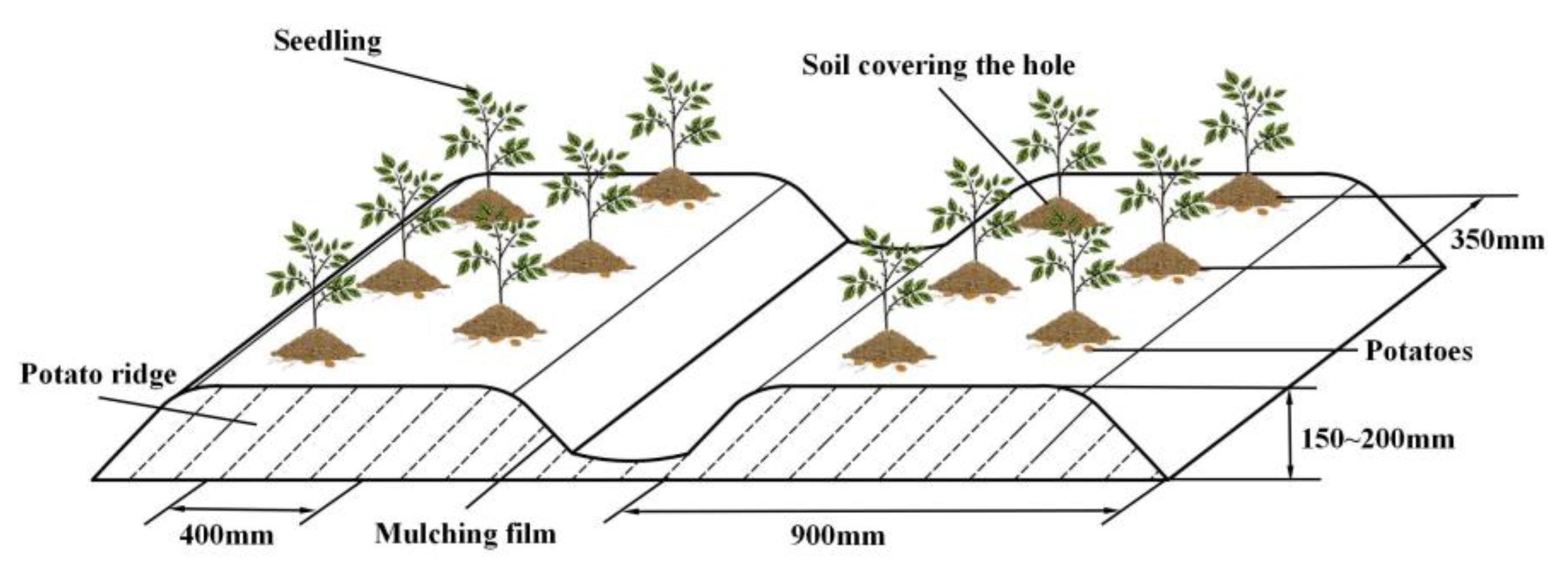
2.1. Agronomic Requirements
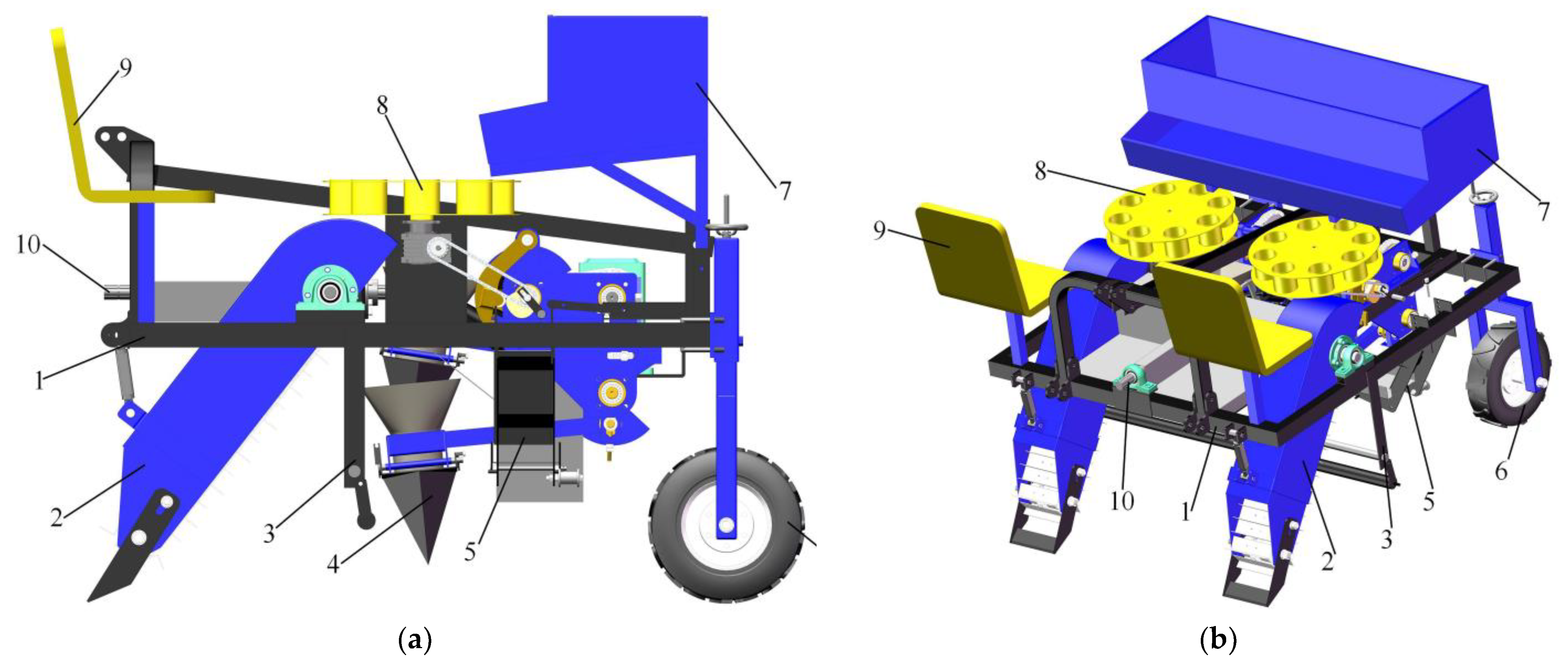
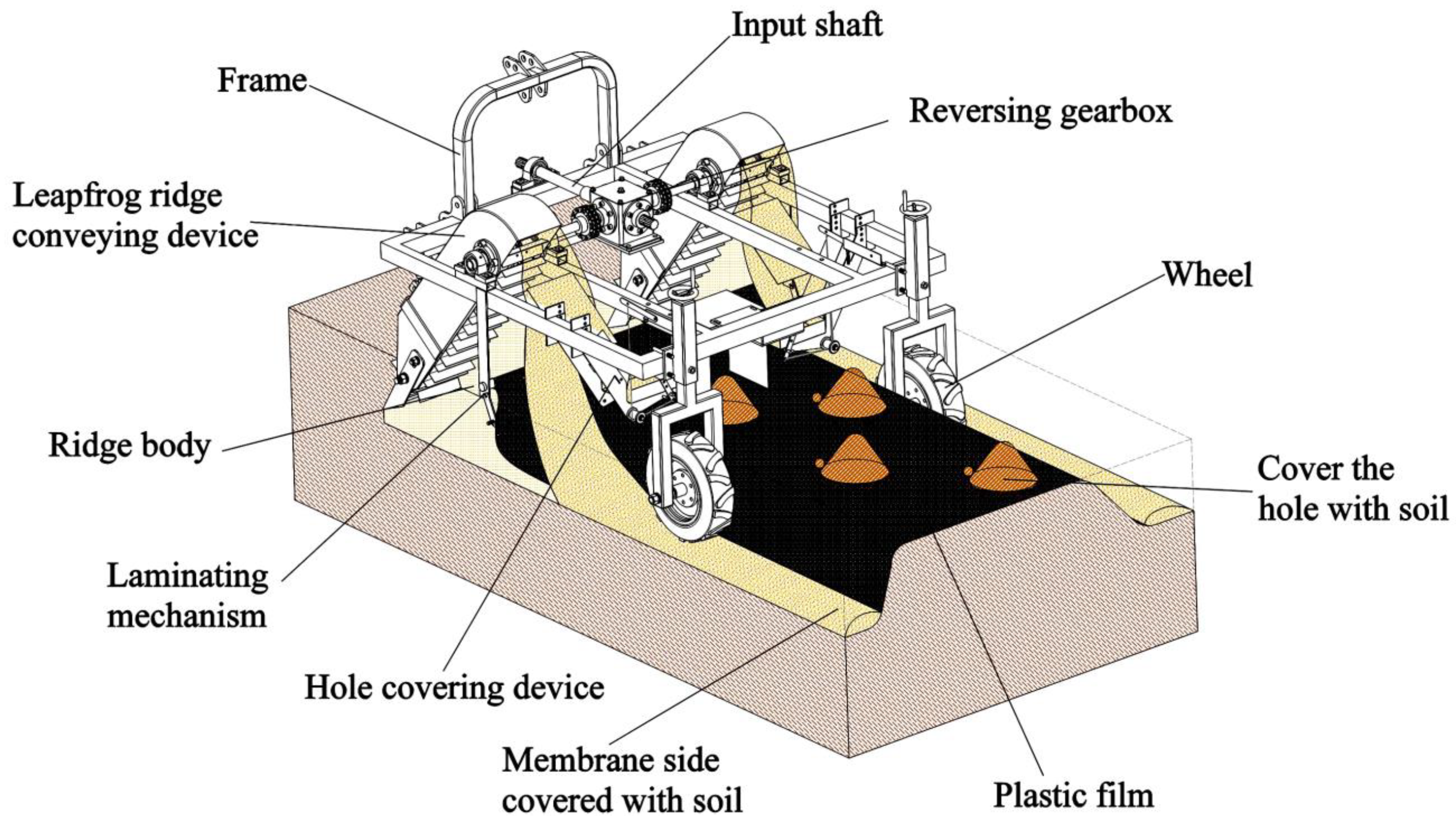
2.2. Overall Structure
2.3. Working Principle
3. Results and Discussion
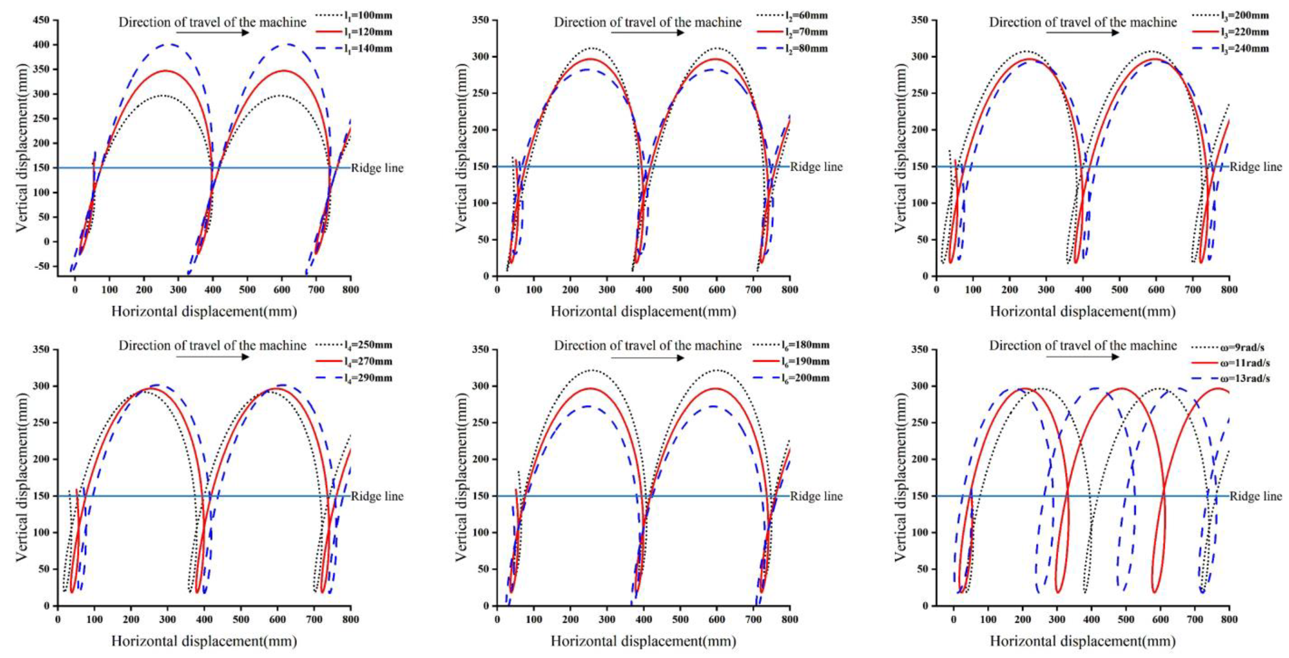
3.1. Film-Piercing and Hole-Punching Mechanism
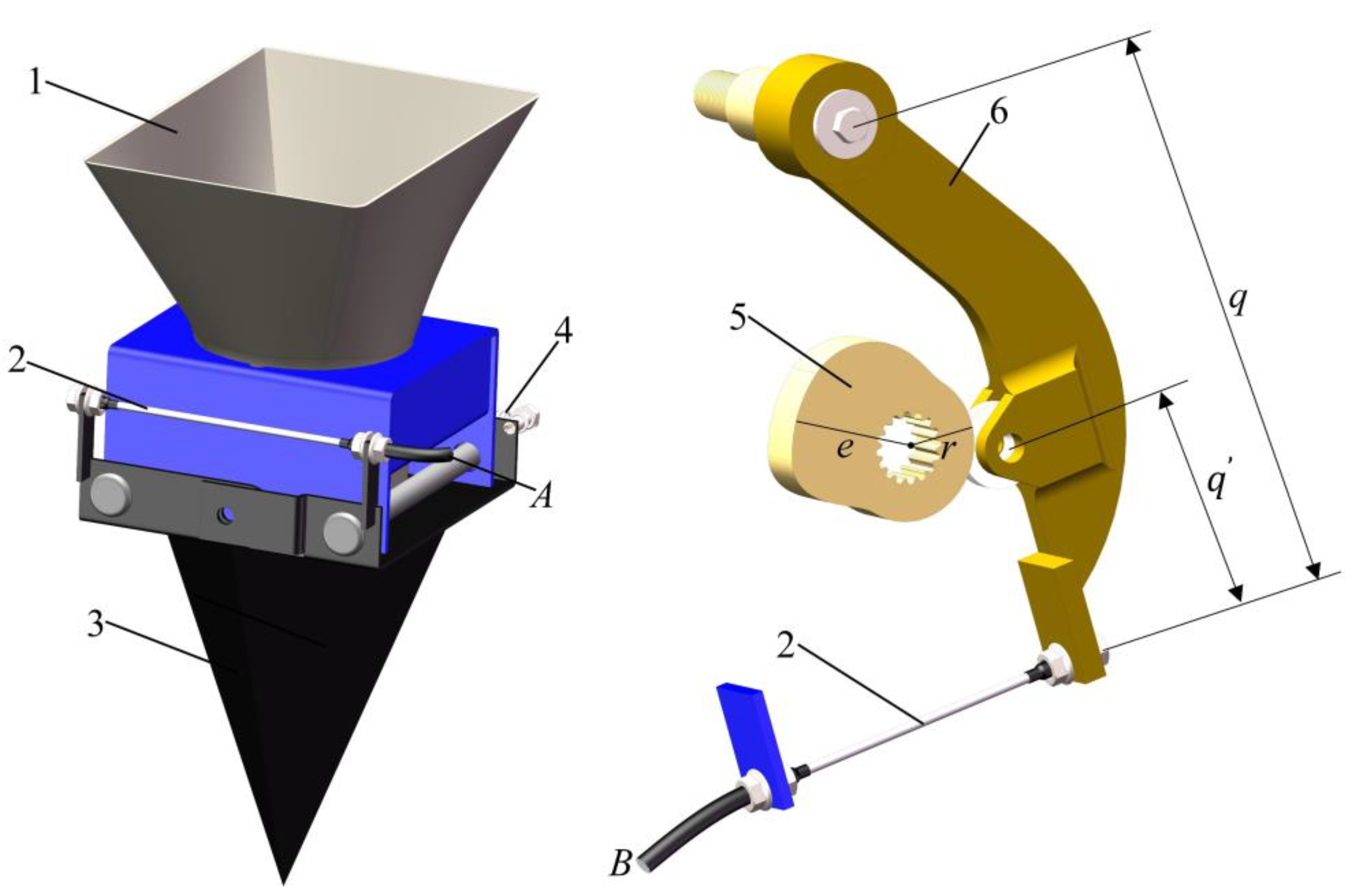
3.2. Dual-Opening Punching and Seeding Mechanism
3.3. The Ridge-Forming and Soil-Covering Mechanism
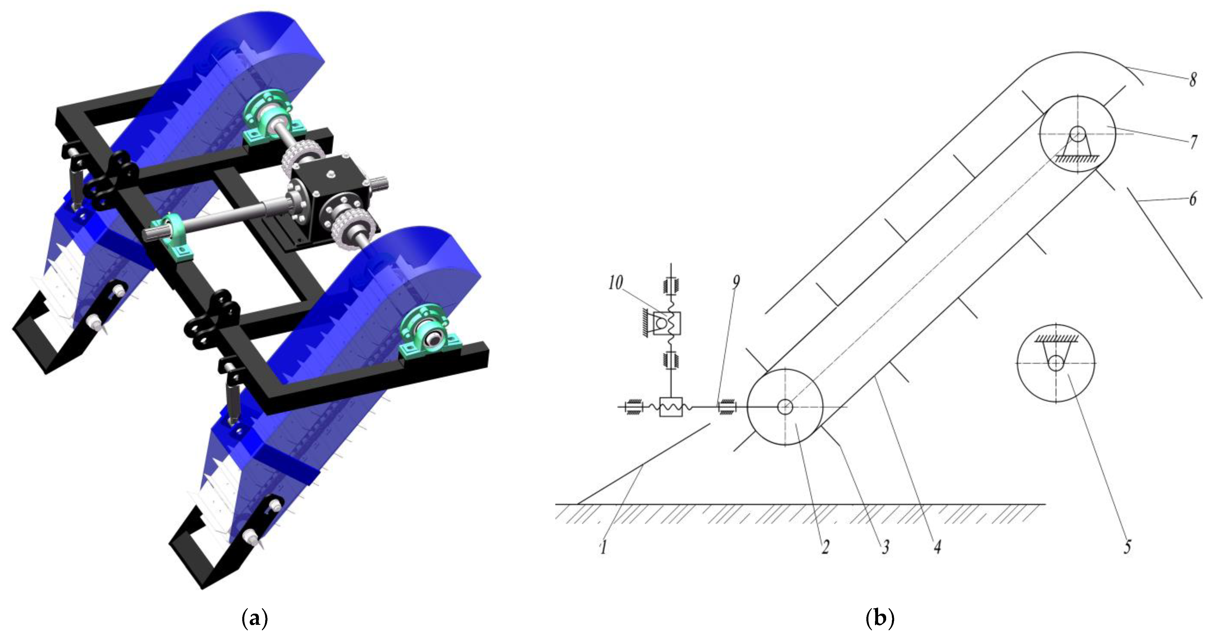
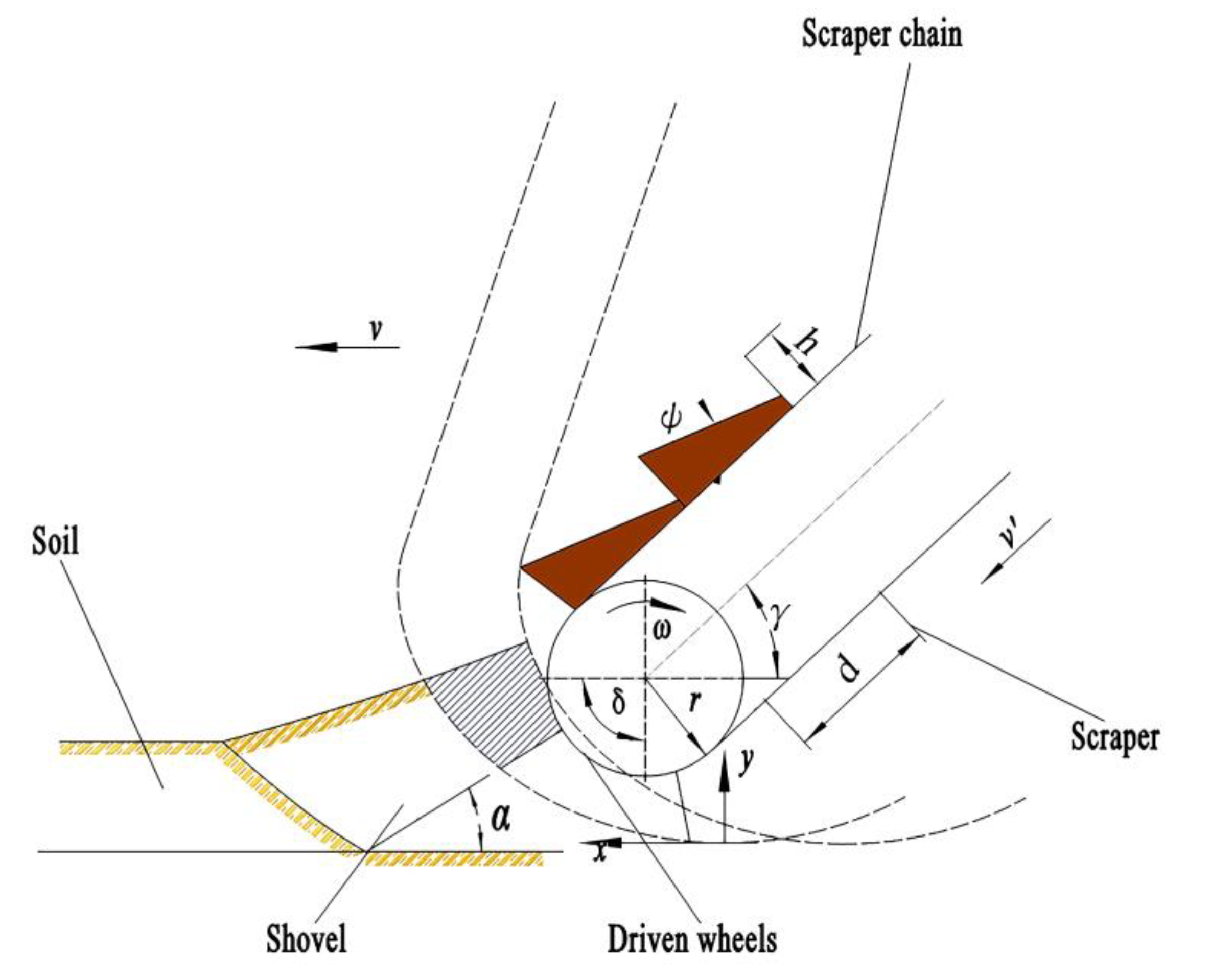
3.3.1. Straddling Ridge-Forming and Soil-Conveying Device
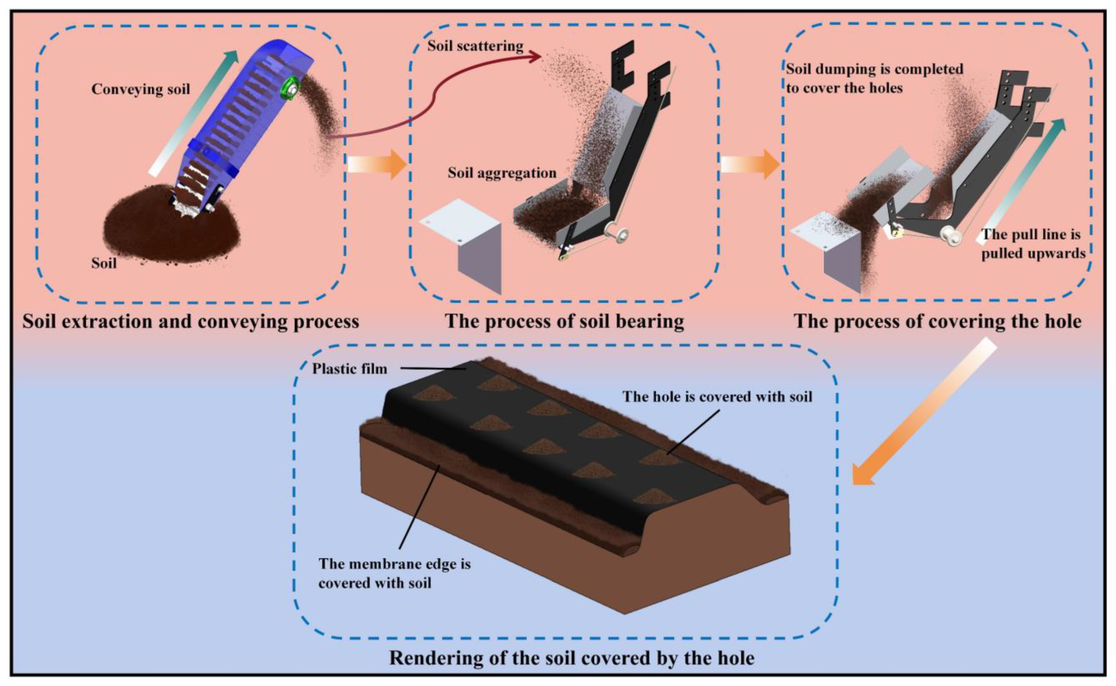
3.3.2. Hole-Covering Device
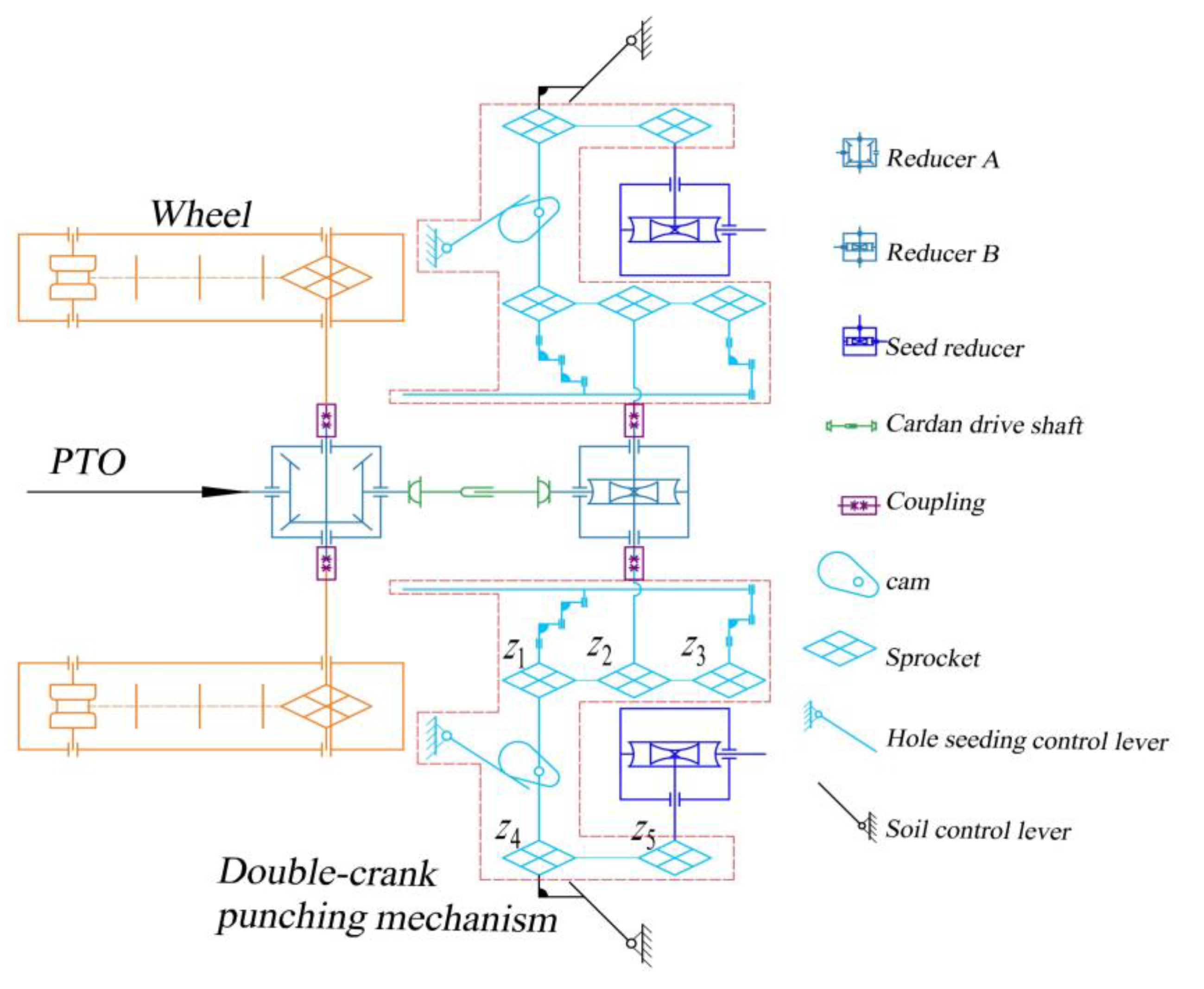
3.4. Transmission System and Seed-Casting Device
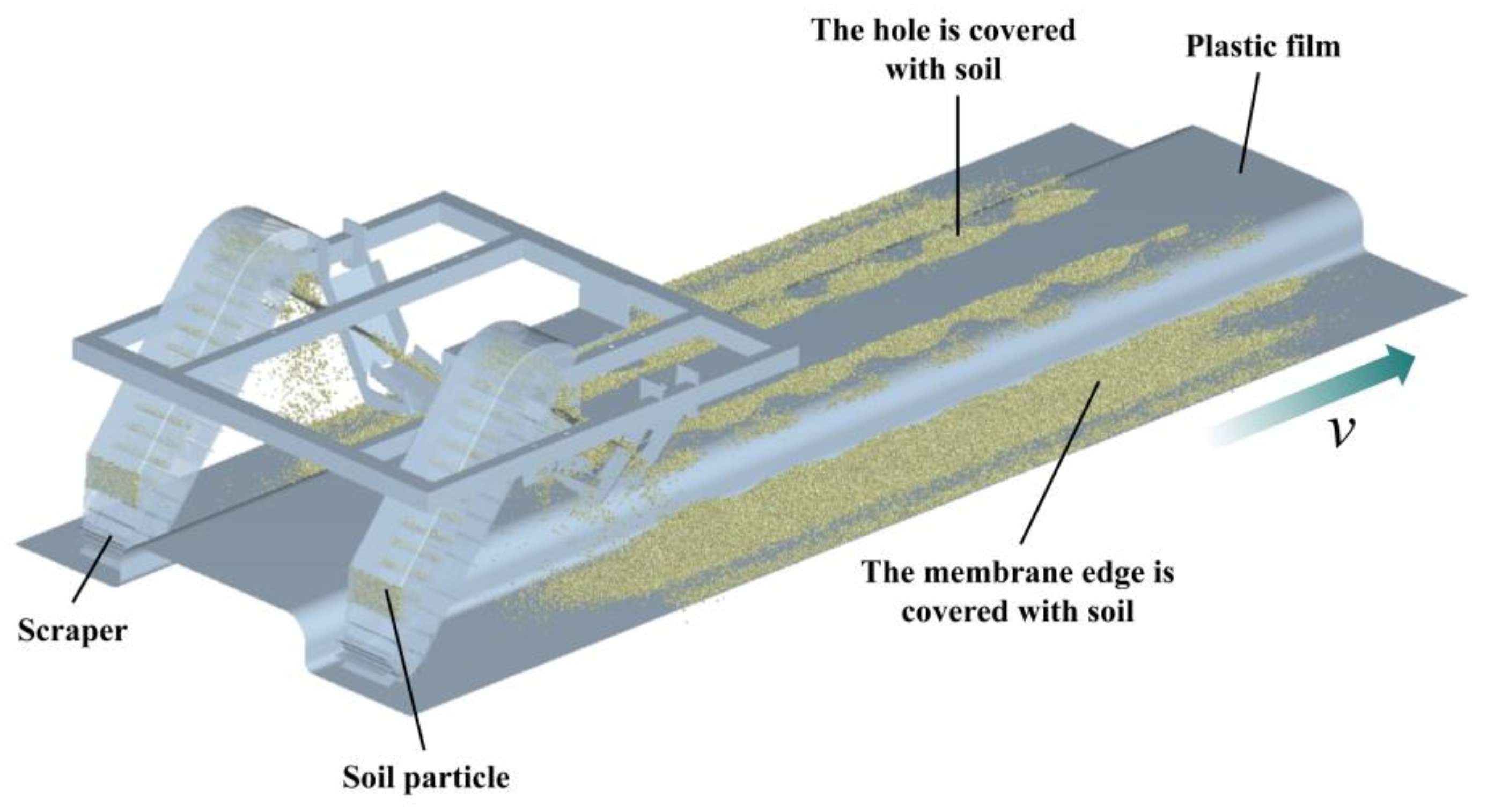
3.5. Simulation and Analysis of Hole-Covering Process
3.5.1. Model Establishment and Parameter Setting
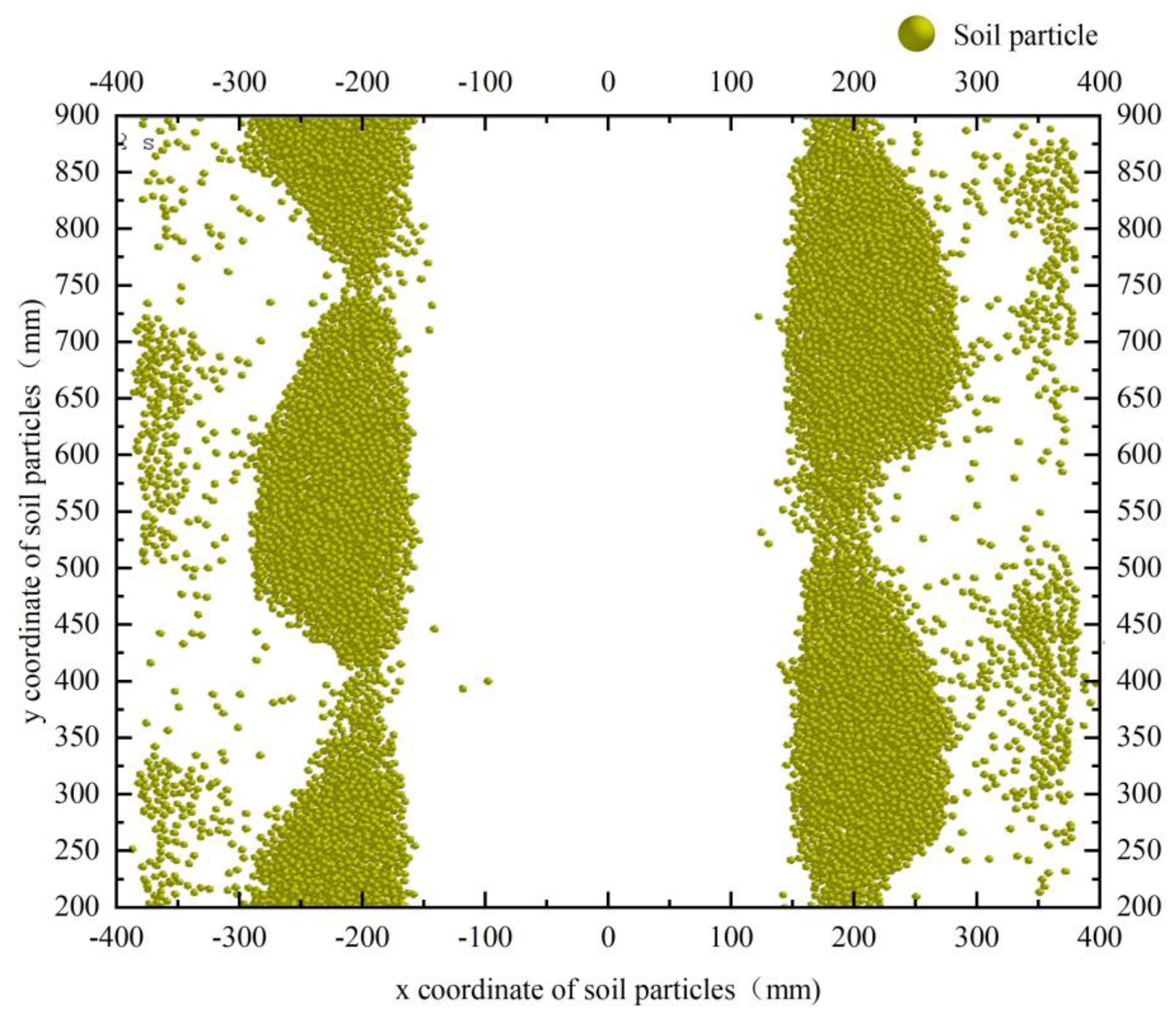
3.5.2. Analysis of Simulation Result
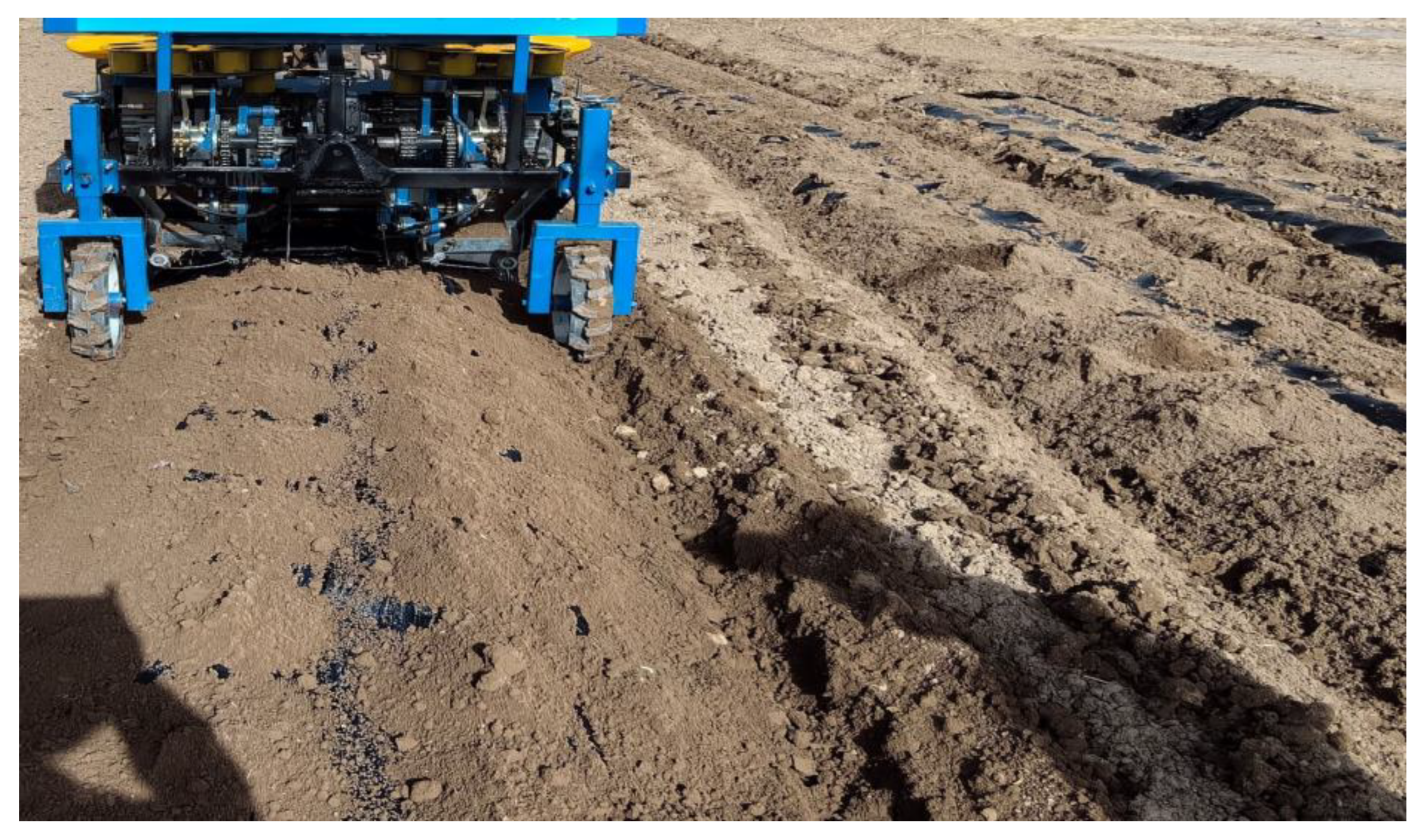
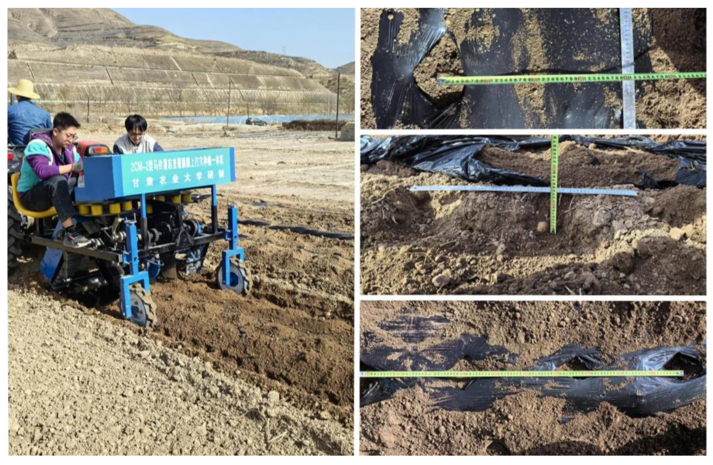
3.6. Field Test
3.6.1. Experimental Conditions and Methods
3.6.2. Test Results and Analysis
4. Conclusions
- (1)
- The field test results indicate that the soil coverage ratio on the hole of mulch, the qualified rate of hole spacing, the misalignment rate of holes, the degree of damage to the light-receiving surface of the film, and the qualified rate of sowing depth under the film are 94.8%, 87.6%, 4.3%, 33.4 , and 95.6%, respectively. The field performance test indicators met the requirements of the national and industry standard, and the actual operation effect conforms to the agronomic requirements for potato planting.
- (2)
- According to the agronomic requirements of potato planting, this study sets the planting row spacing to be 40 cm and plant spacing to be 35 cm. There is a need to coordinate the plant spacing with the forward speed of the machine. The design of a plant spacing control device not affected by the forward speed of the unit is a future research direction. The team has proposed a plant spacing control device based on the principle of stepless speed change to address the existing shortcomings of the machine.
Author Contributions
Funding
Institutional Review Board Statement
Informed Consent Statement
Data Availability Statement
Conflicts of Interest
References
- Brown, C.R. Origin and History of the Potato. Am. Potato J. 1993, 70, 363–373. [Google Scholar] [CrossRef]
- Goffart, J.-P.; Haverkort, A.; Storey, M.; Haase, N.; Martin, M.; Lebrun, P.; Ryckmans, D.; Florins, D.; Demeulemeester, K. Potato Production in Northwestern Europe (Germany, France, the Netherlands, United Kingdom, Belgium): Characteristics, Issues, Challenges and Opportunities. Potato Res. 2022, 65, 503–547. [Google Scholar] [CrossRef] [PubMed]
- Song, Z.H. Scale efficiency and influencing factors of potato production in Northwest China. Chin. Agric. Dig.-Agric. Eng. 2023, 35, 77–80. (In Chinese) [Google Scholar] [CrossRef]
- Zhou, B.; Li, Y.; Zhang, C.; Cao, L.; Li, C.; Xie, S.; Niu, Q. Potato Planter and Planting Technology: A Review of Recent Developments. Agriculture 2022, 12, 1600. [Google Scholar] [CrossRef]
- Li, Z.H.; Wen, X.Y.; Lv, J.Q.; Li, X.C.; Yi, S.J.; Qiao, D. Analysis and Prospect of Research Progress on Key Technologies and Equipments of Mechanization of Potato Planting. J. Agric. Mach. 2019, 50, 1–16. (In Chinese) [Google Scholar] [CrossRef]
- Zhao, H.; Wang, R.-Y.; Ma, B.-L.; Xiong, Y.-C.; Qiang, S.-C.; Wang, C.-L.; Liu, C.-A.; Li, F.-M. Ridge-furrow with full plastic film mulching improves water use efficiency and tuber yields of potato in a semiarid rainfed ecosystem. Field Crops Res. 2014, 161, 137–148. [Google Scholar] [CrossRef]
- Qin, S.; Zhang, J.; Dai, H.; Wang, D.; Li, D. Effect of ridge–furrow and plastic-mulching planting patterns on yield formation and water movement of potato in a semi-arid area. Agric. Water Manag. 2014, 131, 87–94. [Google Scholar] [CrossRef]
- Dai, F.; Xin, S.L.; Zhao, W.Y.; Liu, F.J.; Xin, B.B.; Ma, M.S. Design and experiment of a full film-covered soil potato planting combined operation machine. J. Agric. Mach. 2017, 48, 76–83. (In Chinese) [Google Scholar]
- Zhao, Y.L.; Zhang, D.X. Research on the mechanism of hole punching and seeding on potato film. Agric. Mach. 2005, 11, 103. (In Chinese) [Google Scholar] [CrossRef]
- Fornstrom, J.V.J.J. A precision funch—Planter for sugar beets. Trans. ASAE 1972, 15, 569–571. [Google Scholar] [CrossRef]
- Heinemann, W.H.; Gary, J.W.; Dilworth, A.E. Experimental machines for autodibble planting. Trans. ASAE 1973, 16, 656–659. [Google Scholar] [CrossRef]
- Wang, Z.Y.; Hu, D.J.; Huang, Y.R. The precision roller type hill-drop drill with the punching device on film. Trans. Chin. Soc. Agric. Mach. 1988, 1, 88–95. (In Chinese) [Google Scholar]
- Wei, H.A.; Shao, S.L. Analysis and evaluation on a roller type film mulching hill-drop planter for wheat. J. Gansu Agric. Univ. 2000, 35, 419–423. (In Chinese) [Google Scholar]
- Zhao, W.Y.; Dai, F.; Yang, J.; Shi, Z.L.; Yang, Z.; Shi, L.R. Design and experiment of direct insert precision hill-seeder with corn whole plastic-film mulching on double ridges. Trans. Chin. Soc. Agric. Mach. 2013, 44, 91–97. (In Chinese) [Google Scholar]
- Zhao, J.T.; Zhao, W.Y.; Ren, Y.H.; Niu, H.H. Design and simulation of direct insert corn planting device of furrow seeder with whole plastic-film mulching on double ridges. Trans. Chin. Soc. Agric. Mach. 2010, 41, 40–43. (In Chinese) [Google Scholar]
- Liu, C.L.; Song, J.N.; Wang, J.C. Study on hole former of peanut hill-drop planter mulching film. J. China Agric. Univ. 2007, 12, 61–64. (In Chinese) [Google Scholar]
- Wang, H.T.; Sun, W.; Zhang, H.; Liu, X.L.; Li, H.; Liu, K.Y. Overview of the development of mechanized film mulching technology. Agric. Equip. Veh. Eng. 2022, 60, 7–11. (In Chinese) [Google Scholar]
- Sun, W.; Zhang, H.; Simionescu, P.A. Numerical optimization and experimental validation of a five-link mechanism, potato planter. Proc. Inst. Mech. Eng. Part C J. Mech. Eng. Sci. 2021, 235, 6883–6892. [Google Scholar] [CrossRef]
- Lou, H.D.; Zou, H.J. Advanced Mechanical Principles; Higher Education Press: Brijing, China, 1990. (In Chinese) [Google Scholar]
- Sun, W.; Simionescu, P.A. Parameter Analysis and Field Tests of a Double Crank Multi-Rod under Plastic-Film Hill-Drop Mechanism Potato Planter. Am. J. Potato Res. 2020, 97, 256–264. [Google Scholar] [CrossRef]
- Wen, Y.; Zhang, J.; Tian, J.; Duan, D.; Zhang, Y.; Tan, Y.; Yuan, T.; Li, X. Design of a traction double-row fully automatic transplanter for vegetable plug seedlings. Comput. Electron. Agric. 2021, 182, 106017. [Google Scholar] [CrossRef]
- Liao, Y.T.; Li, C.L.; Liao, Q.X.; Wang, L. Research progress analysis on seeding technology and device of seeder. J. Agric. Mach. 2020, 51, 12. (In Chinese) [Google Scholar]
- Yan, H.; Liu, C.; Li, P.B.; Chen, R.W.; Zhou, H.Y.; Zhuang, T.F. Design and experiment of adjustable duckbill planting device for vegetable transplanter planting static track. J. Agric. Mach. 2023, 54, 71–81. (In Chinese) [Google Scholar]
- Ma, C.L.; Chen, X.G.; Zuo, C.C.; Yu, J.Q.; Wu, Y.C. Study on the basic characteristics of soil working parts of seeders. Trans. Chin. Soc. Agric. Eng. 1992, 04, 41–46. (In Chinese) [Google Scholar]
- Ma, X.; Ma, C.L.; Zhang, S.Q. Study on the furrow opener of plastic film mulch seeder. J. Agric. Mach. 1989, 04, 20–27. (In Chinese) [Google Scholar]
- McLeod, C.D.; Misener, G.C.; Tai, G.C.C.; Caissie, R. A precision seeding device for true potato seed. Am. Potato J. 1992, 69, 255–264. [Google Scholar] [CrossRef]
- Boydas, M.G. Effect of cup size, seed characteristics and angular speed on the performance of an automatic potato planter under laboratory conditions. J. Agric. Sci. 2017, 23, 317–327. [Google Scholar] [CrossRef]
- Sun, W.; Liu, X.L.; Zhang, H.; Wang, H.C.; Tian, B. Design of a potato fertilization and planting ridge-making full-film mulching integrated machine. Trans. Chin. Soc. Agric. Eng. 2017, 33, 14–22. (In Chinese) [Google Scholar]
- Sun, W.; Liu, X.L.; Shi, L.R.; Zhang, H.; Liu, Q.W.; Wu, J.M. Covering characteristics of scraper lifting belt type membrane covering device. J. Mech. Eng. 2016, 52, 38–45. (In Chinese) [Google Scholar] [CrossRef]
- Shi, L.R.; Zhao, W.Y.; Sun, W. Soil particle contact model and parameter calibration of farmland in arid areas of northwest China based on discrete element method. Trans. Chin. Soc. Agric. Eng. 2017, 33, 181–187. (In Chinese) [Google Scholar]
- Dai, F.; Zhang, S.L.; Song, X.F.; Zhao, W.Y.; Ma, H.J.; Zhang, F.W. Design and experiment of a combined operation machine for double-film double-ridge double-width film covering and soil covering. J. Agric. Mach. 2020, 51, 108–117. (In Chinese) [Google Scholar]
- Lu, Q.; Liu, F.J.; Liu, L.J.; Liu, Z.J.; Liu, Y.Q. Establishment and validation of discrete element model for interaction of soil-seed-covering device in furrow seeding. Trans. Chin. Soc. Agric. Mach. 2023, 54, 46–57. (In Chinese) [Google Scholar]
- Liu, Q.; Sun, W.; Wang, H.; Meng, Y. Design and Field Test of a Leaping Type Soil-Covering Device on Plastic Film. Agriculture 2023, 13, 1680. [Google Scholar] [CrossRef]
- GB/T25417-2010; Technical Specifications for Potato Planting Machines. Standards of China: Beijing, China, 2010. (In Chinese)
- GB/T6242-2006; Test Methods for Potato Planter Machinery. Standards of China: Beijing, China, 2006. (In Chinese)
- NY/T987-2006; Quality of Film Mulch Seeder Operation. Standards of China: Beijing, China, 2006. (In Chinese)
- NY/T1415-2021; Technical Specification for Quality Evaluation of Potato Planting Machines. Standards of China: Beijing, China, 2021. (In Chinese)


| Material | Parameter | Numerical Value |
|---|---|---|
| soil | Poisson ratio | 0.4 |
| density/(kg/m3) | 1364 | |
| shear modulus/Mpa | 1 | |
| mulch | Poisson ratio | 0.49 |
| density/(kg/m3) | 1000 | |
| shear modulus/Mpa | 6.1 | |
| hole covering device | Poisson ratio | 0.28 |
| density/(kg/m3) | 7850 | |
| shear modulus/Mpa | 3500 | |
| soil–soil | coefficient of restitution | 0.21 |
| static friction coefficient | 0.68 | |
| rolling friction coefficient | 0.27 | |
| soil–mulch | coefficient of restitution | 0.30 |
| static friction coefficient | 0.42 | |
| rolling friction coefficient | 0.34 | |
| soil–hole-covering device | coefficient of restitution | 0.54 |
| static friction coefficient | 0.31 | |
| rolling friction coefficient | 0.13 |
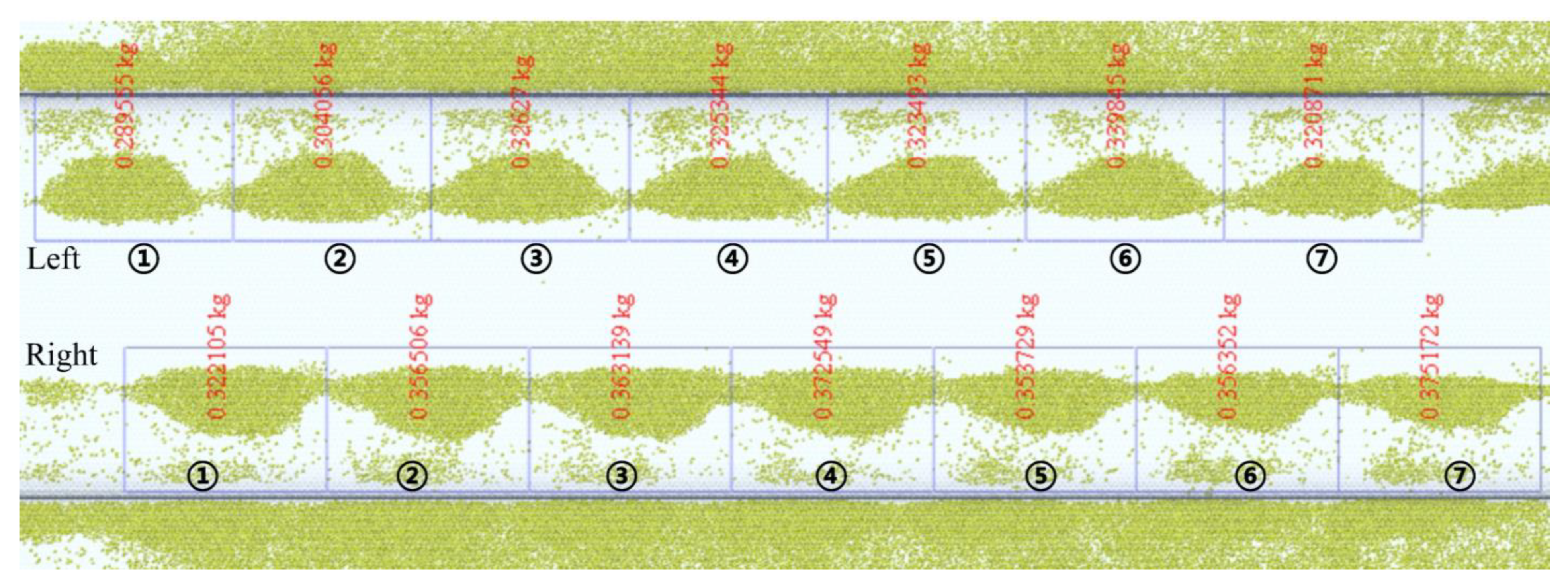
| Number | 1 | 2 | 3 | 4 | 5 | 6 | 7 |
|---|---|---|---|---|---|---|---|
| soil pile mass on left side/kg | 0.29 | 0.30 | 0.33 | 0.33 | 0.32 | 0.34 | 0.32 |
| soil pile mass on right side/kg | 0.32 | 0.36 | 0.36 | 0.37 | 0.35 | 0.36 | 0.38 |
| Item | Average Number | Quality Index |
|---|---|---|
| the soil coverage ratio on the hole of mulch, % | 94.8 | ≥90.0 |
| qualified rate of hole spacing, % | 87.6 | ≥80.0 |
| misalignment rate of boreholes, % | 4.3 | ≤6.0 |
| the degree of damage to the light-receiving surface of the film, | 33.4 | ≤55.0 |
| the qualified rate of sowing depth under the film, % | 95.6 | ≥85.0 |
Disclaimer/Publisher’s Note: The statements, opinions and data contained in all publications are solely those of the individual author(s) and contributor(s) and not of MDPI and/or the editor(s). MDPI and/or the editor(s) disclaim responsibility for any injury to people or property resulting from any ideas, methods, instructions or products referred to in the content. |
© 2024 by the authors. Licensee MDPI, Basel, Switzerland. This article is an open access article distributed under the terms and conditions of the Creative Commons Attribution (CC BY) license (https://creativecommons.org/licenses/by/4.0/).
Share and Cite
Li, B.; Sun, W.; Zhao, Z.; Simionescu, P.A. Development and Validation of a Potato Seeding Machine with Integrated Plastic Film Mulch Punching Mechanism. Agronomy 2024, 14, 1570. https://doi.org/10.3390/agronomy14071570
Li B, Sun W, Zhao Z, Simionescu PA. Development and Validation of a Potato Seeding Machine with Integrated Plastic Film Mulch Punching Mechanism. Agronomy. 2024; 14(7):1570. https://doi.org/10.3390/agronomy14071570
Chicago/Turabian StyleLi, Baowei, Wei Sun, Zhiwei Zhao, and Petru A. Simionescu. 2024. "Development and Validation of a Potato Seeding Machine with Integrated Plastic Film Mulch Punching Mechanism" Agronomy 14, no. 7: 1570. https://doi.org/10.3390/agronomy14071570