Article

Research and Experiment on the Ditching Performance of a Ditching and Film-Covering Machine in the Yellow Sand Cultivation Mode of Solar Greenhouses

1
College of Mechanical and Electrical Engineering, Tarim University, Alar 843300, China
2
Xinjiang Production and Construction Corps Key Laboratory of Utilization and Equipment of Special Agricultural and Forestry Products in Southern Xinjiang, Alar 843300, China
3
Modern Agricultural Engineering Key Laboratory, Universities of Education Department of Xinjiang Uygur Autonomous Region, Alar 843300, China
*
Author to whom correspondence should be addressed.
Agronomy 2024, 14(8), 1704; https://doi.org/10.3390/agronomy14081704
Submission received: 28 June 2024 / Revised: 30 July 2024 / Accepted: 31 July 2024 / Published: 2 August 2024
(This article belongs to the Section Innovative Cropping Systems)

Abstract

:
This research initiative, developed in response to the need for enhanced mechanization efficiency within solar greenhouses, particularly under yellow sand cultivation conditions, introduces an integrated ditching and film-covering machine. A novel spiral staggered throw-cut combined ditching knife was specifically engineered and optimized to meet the exacting agronomic requirements of embedded substrate cultivation. Extensive analyses of soil interactions and the formulation of dynamic equations for soil particles facilitated the determination of key operational parameters: a tangent height of 650 mm for the ditching knife, a soil-throwing width of 300 mm, a piece width of 120 mm, and an inclination angle of 30°. Performance simulations of the ditching knife, conducted using the discrete element method (DEM), revealed superior soil disturbance control and improved soil return compared to conventional designs. Critical operational variables such as forward speed, knife shaft speed, and ditching depth were rigorously tested, with trench depth quality and power consumption as primary evaluation metrics. The results demonstrated that knife shaft speed profoundly influences performance, with optimal operating parameters established through detailed field testing: a speed of 0.5 m/s, a blade shaft speed of 200 rpm, and a ditching depth of 300 mm. Under these optimized conditions, the machine achieved power consumption of 0.668 kW, trench depth stability of 86.7%, a surface width of 413 mm, a bottom width of 304 mm, and an average ditching depth of 310 mm, achieving a qualification rate of 87.1%. The post-ditching soil crushing rate was 92.4%. Both simulation and field evaluations validated that the innovative ditching knife markedly enhances ditching and soil-throwing quality in sandy soil, fulfills agronomic requirements for tomato sowing, and provides an essential reference for the mechanized planting of crops in the yellow sand matrix cultivation mode of solar greenhouses.

1. Introduction

Desertification poses a significant threat to global sustainable development [1]. In northwest China, adverse land conditions have hindered high-quality agricultural advancement [2]. To address the scarcity of arable land resources, China has increasingly turned to facility agriculture in non-arable areas in recent years [3]. Soilless cultivation technologies are gaining popularity within these facilities [4,5], with the adoption of an embedded substrate cultivation model designed to boost crop yields. This model offers multiple benefits: it reduces surface evaporation, conserves soil moisture, collects rainwater, and provides drought resistance. Additionally, it effectively mitigates issues such as low-temperature stress and obstacles related to soil continuous cropping [6,7,8,9,10]. However, the constraints of space and the characteristics of sandy soil in solar greenhouses present challenges for traditional ditching and film-covering machines, making them inefficient [11,12,13]. Therefore, developing ditching devices tailored to the yellow sand cultivation model of solar greenhouses is crucial.
Internationally, countries such as Germany, the United Kingdom, the United States, and Canada have pioneered research in the field of furrowing and film-covering equipment and have widely implemented such technologies [14]. Japan commenced related research in 1948 and has been at the forefront of promoting furrowing and film-covering sowing, with its machinery, like ridging and film-covering machines and film-covering seeders, being extensively utilized [15,16,17]. In 2023, Hamroqul Ravshanov et al. [18] developed an advanced furrowing knife capable of achieving a 180° flip of the soil layer by optimizing its height, length, wing angle, and installation angle, thus enhancing the environment for crop roots. However, the loose nature of sandy soil means that a 180° flip can lead to unstable furrowing, potentially compromising planting results. The deep furrowing knife designed by Sukhbir Singh et al. [19] allows for adjustments in speed and depth to manage soil disturbance and meet varying tension requirements, although fluctuations in tension during operations in yellow sand can impact consistency and operational stability. The curved-leg furrowing knife by James Barr et al. [20] minimizes soil disturbance through its streamlined design and optimized thickness, though it requires further experimentation and design enhancements to cope with the unique properties of sandy soil. K Ravshanov et al. [21] designed a multifunctional furrowing machine that creates irrigation furrows along the symmetrical axis of the sowing area, optimizing water resource utilization and improving irrigation efficiency. However, in yellow sand environments, these furrows are prone to instability and collapse, necessitating design improvements for furrow stability. Neil B. McLaughlin et al. [22] analyzed two different furrowing knives, providing insights into adapting to various soils and planting conditions, aiding the design of tools suitable for yellow sand cultivation. These tools must be optimized for local soil conditions to ensure reduced resistance, enhanced operational efficiency, and stability in loose sand. Nevertheless, due to the distinct soil characteristics found abroad, the predominant trend in machinery development focuses on high horsepower and broad widths, which demand high technical expertise and are challenging for farmers to operate, particularly in areas of severe desertification like Northwest China [23,24,25].
With the acceleration of agricultural modernization, the level of agricultural mechanization in China has continuously improved [26]. Zeng Yi et al. [27] developed a layered ditching cutter, analyzing the interaction between soil and soil-cutting blades and establishing the dynamic differential equation of soil particles on the blade surface, which enhanced the cutter’s stability and efficiency. However, the abrasive nature of sandy soil increases blade wear and affects the normal cutting functions, necessitating a specially designed adaptation. Liu et al. [28] utilized EDEM 2020 software and coarse-grained modeling technology to develop a reverse-rotation ditching machine roller suitable for vineyard soil in southern China, enhancing calculation efficiency and model accuracy. Nonetheless, the reverse-rotation roller’s weak soil-casting ability requires further model adjustments and optimization for yellow sand to ensure its precision and applicability in diverse environments. The forest ditching cutter designed by Chen Yufeng et al. [29] improves cutting efficiency and stability under harsh forest conditions, but the significant differences in soil mechanical properties between yellow sand and forest land necessitate recalibration and adjustments to adapt to the yellow sand environment. Zhang Mingwei and his team [30] designed a new rotary tillage ditching knife by integrating the agronomic requirements of wheat, soybeans, and corn, effectively enhancing the overall performance of mechanized operations. However, the stability and soil-throwing ability of the ditching knife were not elaborated upon in detail. Cai Yuchen et al. [31] developed a self-propelled vegetable garden ditching and fertilizing machine with a modular design, which allows for the replacement of different operating tools, facilitating multi-purpose use, improving agricultural machinery utilization in hilly and mountainous areas, and reducing labor costs. However, the machine faces issues of low ditching quality and high power consumption during operation. In 2022, Xu et al. [32] from Shandong Agricultural University addressed the problems of large amplitude and poor stability of double-row ditching and fertilizing machines in orchards. They designed a new ditching and fertilizing machine that transfers excavated soil to a soil covering shell, enabling efficient soil backfilling operations. This design, integrating ditching, fertilizing, and covering operations, has mitigated issues of large amplitude and poor stability, although the excavated trenches remain unstable, with significant soil backfill.
The research outlined above provides essential technical and equipment support for the mechanization of facility agriculture. In addressing the identified issues and in alignment with the yellow sand matrix cultivation mode, a multifunctional furrowing and film-covering machine was developed for use in solar greenhouses. This machine integrates furrowing, film covering, shaping, and soil covering. The performance of the machine, specifically the furrowing efficiency and power consumption, was evaluated using experimental indicators. A discrete element model was created to simulate the interaction between the furrowing knife and the soil, with the analysis conducted using EDEM 2020 software. This simulation helped to explore the impact of the furrowing knife’s design and operational parameters on its performance. Theoretical analyses and optimizations were subsequently performed to determine the optimal configuration of the furrowing knife and its operating parameters. Ultimately, field tests were carried out to confirm the feasibility and effectiveness of the machine.

2. Materials and Methods

2.1. Agronomic Requirements

To enhance production efficiency and mitigate secondary soil salinization, this study implemented an embedded substrate cultivation model. This model involves constructing isolation trenches (planting ditches) with specific dimensions: 300 mm deep, 400 mm wide at the surface, 300 mm wide at the bottom, and 800 mm apart. Each trench is lined with a 0.1 mm thick polyethylene film, creating a physical barrier that significantly reduces pest and disease infestation in crops. Additionally, slag and yellow sand are thoroughly mixed in a 3:5 mass ratio and evenly distributed in the trenches to enhance soil aeration and drainage, thereby fostering optimal root growth and improving land utilization. The detailed formation process is illustrated in Figure 1.

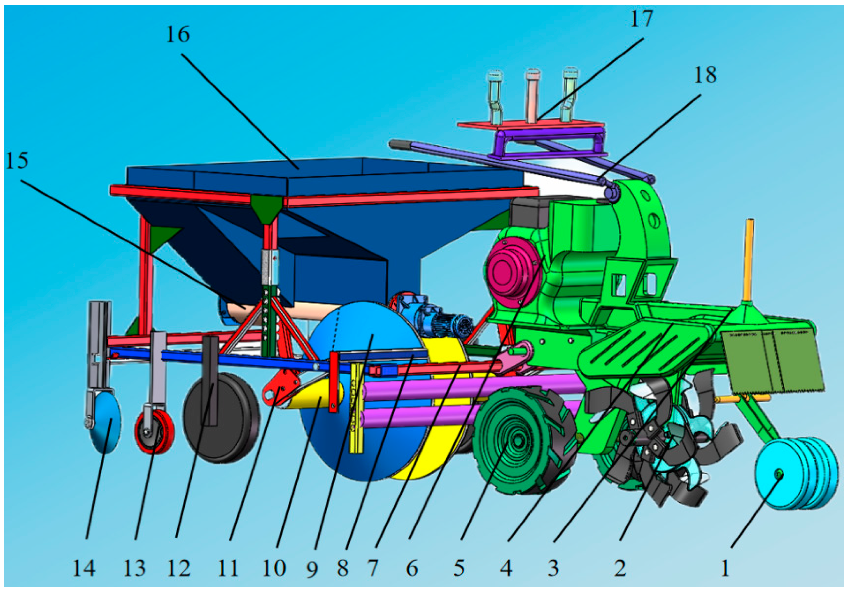
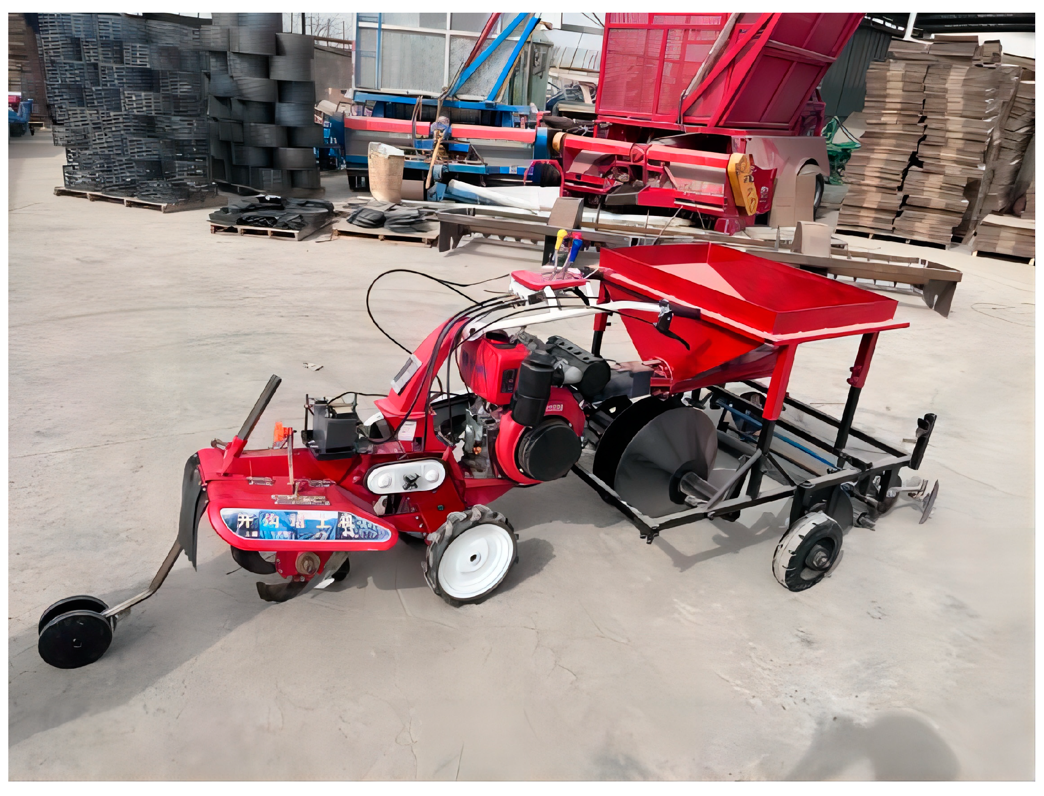
2.2. The Overall Structure of the Equipment

The ditching and film-covering machine is composed of several crucial components: a guiding and depth-limiting mechanism, a structural frame, a soil-retaining and backflow device, a driving wheel, a gearbox, a fuel tank, a film-covering mechanism, a trapezoidal pressing mechanism, and a matrix-laying mechanism. The schematic representation of the machine’s structure is depicted in Figure 2.

2.3. Working Principle

The guide and depth limiter comprise a support frame and a guide wheel, allowing for precise ditching depth control by adjusting the guide wheel’s height. The control device, featuring a handheld control frame and a gear adjustment system, ensures operational flexibility and accuracy. Power transmission during operation is facilitated by a pulley, which splits the power to drive both the ditching cutter shaft via the gearbox and the machine forward. The ditching cutter, driven by a rotary tiller, features a spiral staggered arrangement and rotates counterclockwise to effectively crush and evenly distribute the soil to both sides of the trench. A retaining plate positioned above the trencher ensures even distribution of soil to the trench edges, prevents soil fallback, and maintains the trench’s accurate dimensions. The film-covering device, located at the front end of the frame, performs the film-covering operation in sync with the machine’s forward movement. Additionally, a walking suppression device compacts and secures both the film material and the planting trench simultaneously. Meanwhile, a matrix box mounted above the frame evenly distributes the matrix into the planting trench during operation to facilitate the matrix arrangement process.

2.4. Design of Key Components

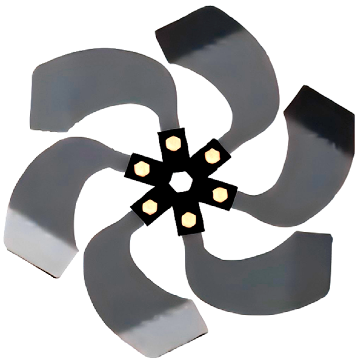
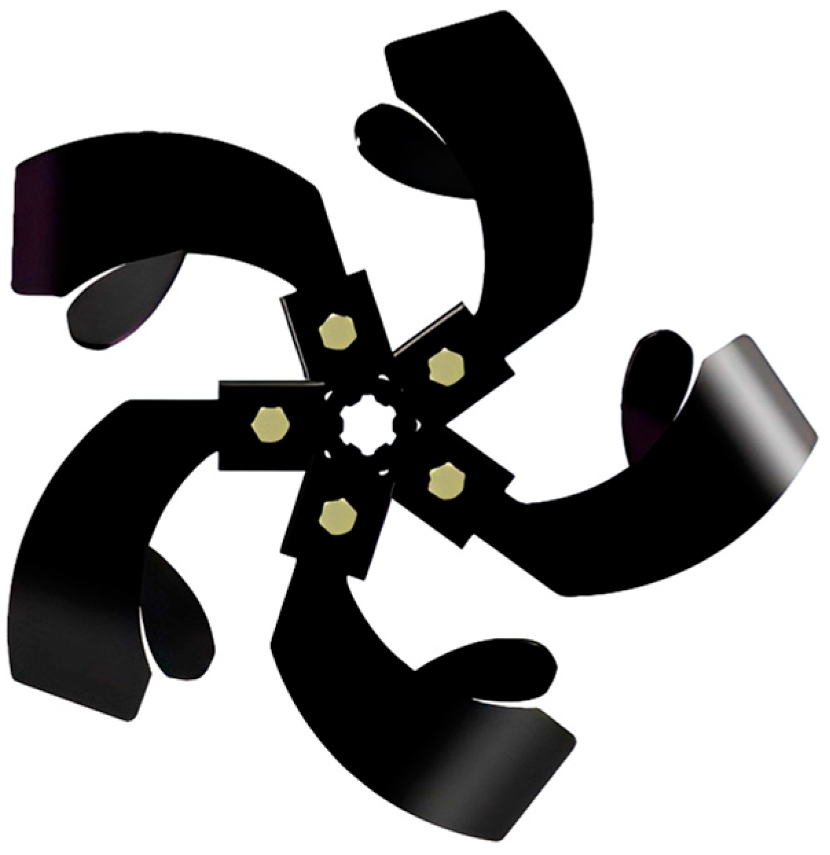
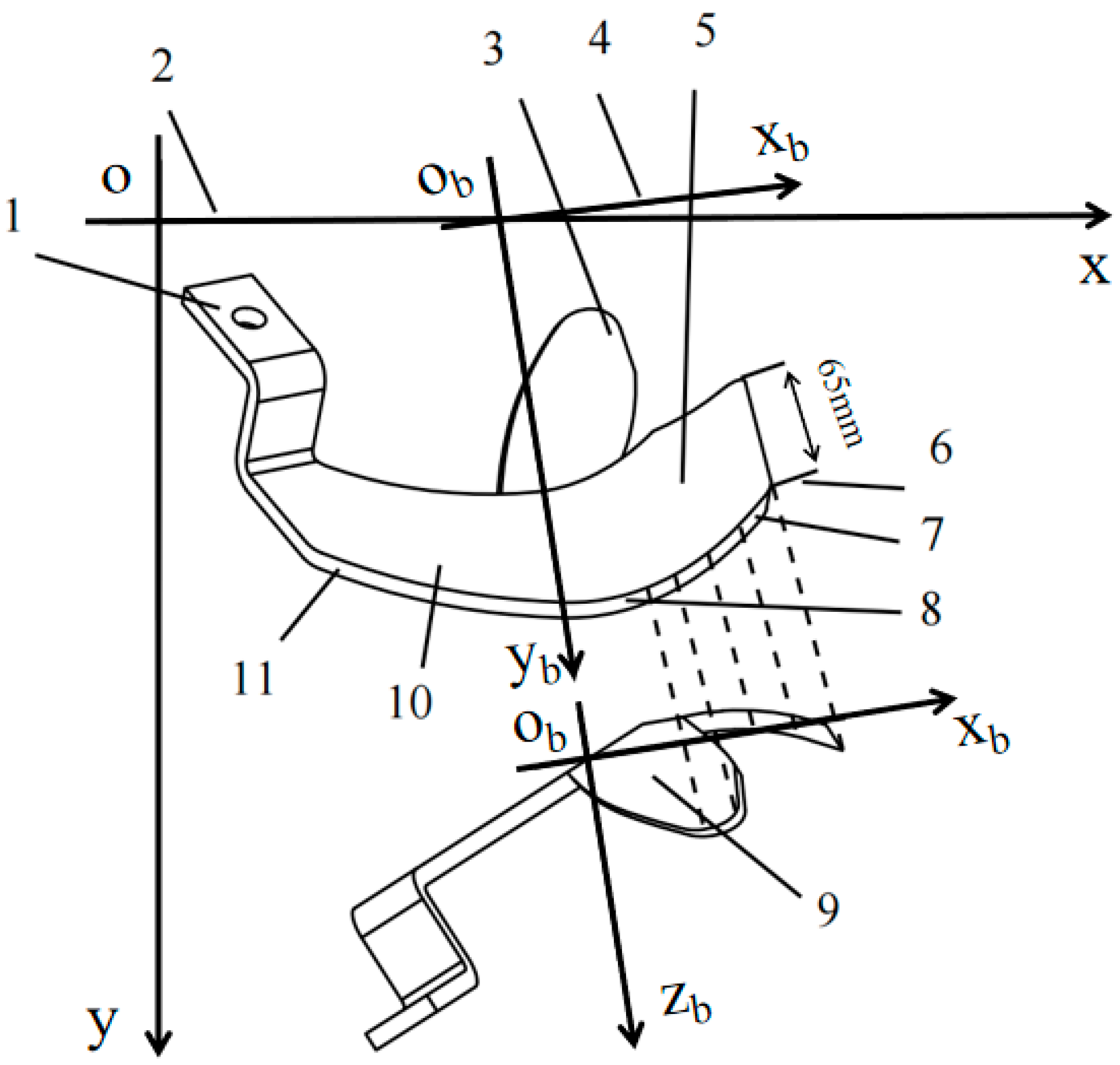
2.4.1. Design of Throw-Cut Combined Ditching Knife

Traditional plowshare and chain-knife furrowing devices encounter significant tillage resistance during operation and necessitate high engine power [33]. In contrast, rotary tillage furrowing devices boast a simpler structure, superior soil cutting and crushing performance, stable operation, and lower power consumption [34], making them ideal for the planting requirements of facility agriculture. Currently, disc-type furrowing knives typically feature universally spaced rotary tillage knives arranged equidistantly around the circumference, as depicted in Figure 3. Although effective in soil cutting, this design exhibits inadequate soil-throwing capabilities, often resulting in insufficient furrowing width and significant soil return, which fail to meet the operational needs of solar greenhouses. To address this issue, this study introduced an innovative combined ditching knife that enhances both soil-throwing and cutting capabilities, tailored to the predominantly sandy and gravelly soil conditions of Northwest China. The newly designed device incorporates staggered rotary tillage knives for cutting, supplemented by additional soil-throwing blades to optimize soil displacement, as illustrated in Figure 4.

2.4.2. Key Parameter Optimization

To satisfy the agronomic requirement of maintaining the furrow depth at approximately 300 mm, key parameters of the traditional IT245 (Nangong Tianshu Welding Material Manufacturing Factory, Nangong, China) rotary tiller have been modified. To boost the soil-crushing capabilities of the combined ditching blade, increasing the end height of the cutter’s tangent surface significantly improved its performance [35]. At an end height of 65 mm for the tangent surface, both the soil crushing rate and power consumption reach their optimal levels. Consequently, the end height of the tangent surface on the soil-throwing blade was adjusted from 40 mm to 65 mm, while all other parameters remained unchanged. The enhanced tool structure is depicted in Figure 5.
The rotation center of the ditching cutter shaft is set as the coordinate origin. The forward direction of the machine is designated as the x-axis, while the positive direction of the y-axis is vertically upward, forming a rectangular coordinate system. The endpoint of the blade coincides with the y-axis. The motion diagram is shown in Figure 6. The motion equations are shown in Formulas (1)–(3).
x = R c o s ω t + v m t
y = R s i n ω t
λ = R ω v m
The absolute velocity v of the endpoint of the grooving blade is given by Formula (4).
v = v x 2 + v y 2 = v o 2 + R 2 2 v m R ω s i n ω t
In the formula, R is the rotation radius of the rotary tiller, mm; ω is the rotation angular velocity of the rotary tiller, rad/s; vf is the forward speed of the implement, m/s; λ is the rotation speed ratio; and t is the time, s.
The speed ratio of the rotary tillage significantly affects the performance of the ditching knife, as illustrated in Figure 7. At a speed ratio (λ) of 1, the endpoint of the ditching knife follows a cycloid path where it does not perform backward soil cutting, consequently failing to crush the soil effectively. When λ is less than 1, the horizontal velocity component of the ditching knife’s endpoint is consistently directed forward, coinciding with the movement of the rotary tiller, resulting in a curtate cycloid path. In this scenario, the knife is unable to cut backward and instead pushes the soil forward, thus hindering optimal functionality. In contrast, at a speed ratio greater than 1, the motion trajectory of the ditching knife forms a prolate cycloid. In this case, the endpoint’s horizontal velocity component is reversed, aligning opposite to the machine’s forward motion, which allows the knife to engage in effective backward soil cutting. This configuration enhances the ditching and soil-loosening processes, thereby significantly improving the overall ditching quality.
The diameter of the cutter head affects the ditching power consumption. The calculation formula is shown in Equation (5).
D = 1.2 ~ 1.4 H 1
D = 360 ~ 420   m m
In Formulas (5) and (6), H1 is the grooving depth, mm, and D is the cutter head diameter, mm.
To fulfill the agronomic requirements of facility agriculture, the ditching depth must reach 300 mm [36]. The throw-cut combined ditching knife is designed with a knife disc rotation diameter of 400 mm to ensure efficient soil cutting and distribution to the trench surface while minimizing power consumption. The soil-cutting pitch significantly affects the soil crushing effect and the stability of ditching and ridge formation. Different soils and crops necessitate specific soil-cutting pitches. Generally, a larger pitch results in a lower rate of soil crushing. For soils with low viscosity and high water content, a smaller pitch is preferable. Conversely, for soils with high viscosity and low water content, a larger pitch should be selected. The specific formula for determining the optimal pitch is provided below.
S = v m t s = v m 2 π R λ z = 60 v m z n
In Formula (7), S is the soil-cutting pitch; z is the number of rotary tillage knives installed, pcs; N is the knife shaft speed, rpm; vm is the forward speed of the implement, m/s; ts is the working rotation time of the knife disc, s; R is the knife disc radius, mm; ω is the knife disc angular velocity, rad/s; and λ is the rotary tillage speed ratio.
From the analysis, it is evident that modifying the forward speed of the machine, the number of blades, and the rotational speed of the cutter disc alters the soil-cutting pitch. Utilizing a small hand-held rotary tiller as the driving mechanism, set at a forward speed of 0.5 m/s, the soil-cutting pitch for the furrowing and ridging knives is determined to range between 15–50 mm.

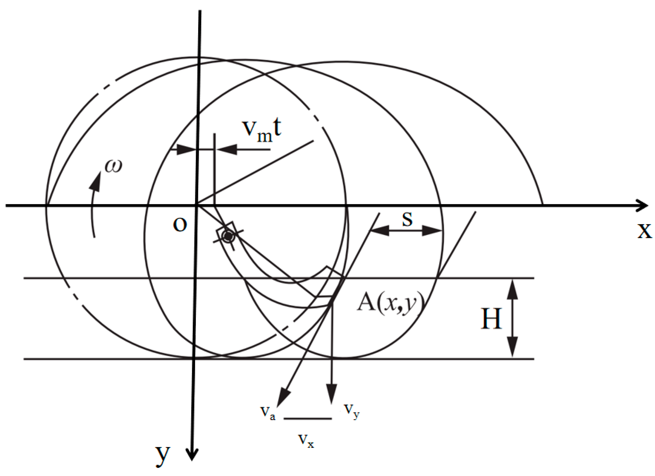
2.4.3. Analysis of the Soil-Throwing Process

The throw-cut combined furrowing knife is adept at laterally displacing soil to predetermined positions, a functionality attributed to its specialized soil-throwing piece structure. In line with the agronomic specifications for embedded substrate cultivation, it is imperative that the soil be uniformly distributed to a distance of 300 mm from the furrow’s edge during the furrowing process, aiding in the efficiency of subsequent film-covering operations. Accordingly, the design parameters for the inclination angle and width of the soil-throwing piece are crucial. Given that the soil in the northwest region predominantly consists of sandy soil, characterized by its discrete particle nature, these soil particles can be accurately described as individual entities. As these particles depart from the soil-throwing piece, they follow a parabolic trajectory, as depicted in Figure 8.
The distance the soil travels from the throwing piece is given by the following formula:
C = v 2 s i n ( 2 θ ) g
v 2 = v x 2 + v y 2 + v z 2
In Formulas (8) and (9), C is the throwing distance, m; v is the initial velocity when thrown, m/s; θ is the angle between initial velocity and ground when thrown, °; g is the gravitational acceleration, 9.8 m/s2; and vx, vy, and vz are the components of initial velocity v in a three-dimensional rectangular coordinate system, m/s.
As can be seen from Figure 7, the horizontal throwing distance is:
H = C s i n θ 1
In Formula (10), θ1 is the angle between the projection of v on the ground and vx, °; H is the horizontal distance of soil-throwing, m; and θ1 satisfies tan(θ1) = vy/vx.
Substituting Equations (9) and (10) into Equation (8), we obtain:
H = v x 2 + v y 2 + v z 2 s i n 2 θ v y g v x 2 + v y 2

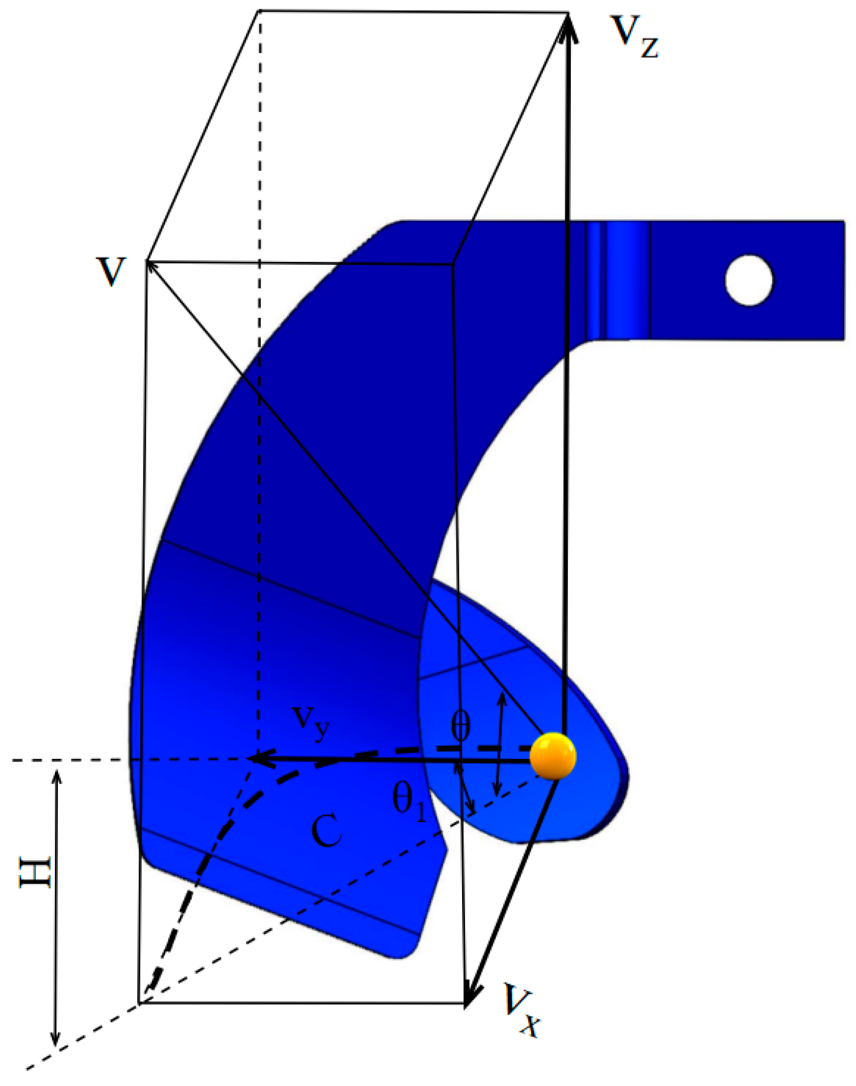
2.4.4. Force Analysis of Soil-Throwing Piece

The width and inclination angle of the soil-throwing blade affect the velocity components vx, vy, and vz. To determine the appropriate parameters for the soil-throwing blade, a dynamic analysis of the thrown soil is necessary. In Figure 9, the coordinate system oxyz is established. Here, o represents the rotation center of the soil-throwing blade. The positive direction of the y-axis aligns with the forward direction of the machine. The x-axis is horizontal, and the z-axis is vertically upward. The front handle of the soil-throwing blade is located in the yoz plane. To conveniently represent the relevant parameters of the soil-throwing blade, the intersection of the long side and the short side of the soil-throwing blade is taken as the origin o1. The short side is defined as the x1-axis, and the long side as the y1-axis. On the plane of the soil-throwing blade, the coordinate system x1o1y1 is established. The angle between this coordinate system and the yoz plane is γ (inclination angle), and the angle between this coordinate system and the xoy plane is β.
Based on the angular relationship between the soil-throwing piece and the yoz and xoy planes, the velocity components vx, vy, and vz are expressed as follows:
v x = v r s i n γ ( s i n β ) + v m v y = 1 2 v r s i n ( 2 a ) 1 2 v r s i n ( 2 γ ) c o s β + v a v z = v r ( c o s 2 γ v r s i n 2 γ c o s β + ω r 1 c o s ( ω t ) )
In Formula (12), r1 is the radius of rotation of point o1, m; vr is the relative speed of soil sliding on the surface of the soil-throwing blade, m/s; ω is the angular speed of rotation of the ditching cutter, rpm; vm is the speed of soil moving forward with the ditching machine, m/s; va is the involved speed of soil driven by the rotation of the soil-throwing cutter, m/s; and vx, vy, and vz are the components of the absolute speed v in the three-dimensional rectangular coordinate system.
The absolute speed v of soil on the soil-throwing blade is the vector sum of the involved speed va driven by the rotation of the soil-throwing cutter, the relative speed vr of soil sliding on the surface of the soil-throwing blade, and the speed of soil moving forward with the ditching machine vm [37]. Therefore, these speeds can be solved separately and then summed vectorially. The direction of the involved speed va is the negative direction of the y-axis, and the calculation formula is:
v a = r 1 s i n π 2 δ 2 ω x 1 s i n ( π 2 γ ) ω
In Formula (13), x1 is the instantaneous horizontal coordinate of the soil particle on the surface of the throw blade and δ2 is the angle between r1 and the y-axis, °.
To solve for the relative speed vr of the soil sliding on the surface of the throw blade, it is necessary to analyze the forces acting on the soil particles on the throw blade. As shown in Figure 8, the soil is subjected to gravity, centrifugal force, Coriolis force, and friction under the rotation of the throw blade. The components of gravity Gx and Gy on the x1 and y1 axes are both mgsinγcosβ. The components of centrifugal force Flx and Fly on the x1 and y1 axes are calculated as follows:
F l x = m ω 2 r 1 s i n π 2 δ 2 x 1 s i n π 2 β c o s γ c o s β F l y = m ω 2 r 1 s i n π 2 δ 2 x 1 s i n π 2 β s i n γ c o s β
Let k = cosβcosγ. The components Fgx and Fgy of the Coriolis force on the x1 and y1 axes are as follows:
F g x = 2 ω v r k s i n ρ F g y = 2 ω v r k c o s ρ
Let k1 = ω2(r1cosδ2 − x1cosβ). The components of the friction force Ffx, Ffy on the x1, y1 axes are as follows:
F f x = m f s i n ρ s i n β g s i n γ + k 1 + 2 v r ω c o s ρ s i n γ + s i n ρ c o s β
In Formula (16), ρ is the angle between the soil relative velocity and the x1 axis, °; F is the friction factor between soil particles and the surface of the soil-throwing piece.
Additionally, according to the geometric relationship, the direction of the relative velocity vr satisfies:
t a n ρ = G x + F l x + F g x + F f x G y + F l y + F g y + F f y = s i n γ c o s γ
When the soil slides from the side and tangent planes of the thrower to the y1 axis of the thrower, the direction of the relative velocity vr coincides with the x1 axis. Thus, the angle ρ is 0°, and the soil is only affected by gravity and centrifugal force. At this time, Equation (17) can be derived as follows:
g = ω c o s β r 1 c o s δ 2 + x 1 c o s β t a n γ
Given that the end height of the tangent surface of the soil-throwing knife is 65 mm and the curves of the tangent edge and the side cutting edge remain unchanged, the position of point o1 can be determined. At this time, the turning radius r1 of point o1 is 230 mm, and the turning radius angle δ2 of point o1 is 60°. The soil-throwing piece is made of manganese steel, and the soil is mostly sandy loam with a friction coefficient f of 0.65 [38]. Since the soil-throwing piece and the tangent part are inclined along the bending line, with the inclination angle consistent with the tangent part, the angle β matches the bending angle of the soil-throwing knife, which is 60° [39]. The forward speed of the machine is 0.5 m/s. The blade shaft speed is 200 r/min, corresponding to ω of 20.94 rad/s. According to the agronomic requirement of throwing soil to the ditch edge with a width of 300 mm in the greenhouse, the soil-throwing width S is taken as 300 mm. The above parameters are substituted into Equations (12), (17), and (18) to solve for the unknowns γ, b, and vr. By eliminating vr using the elimination method, the values are found to be γ = 30° and x1 = 120. At this time, the lateral soil-throwing distance is 300 mm, so the width b of the soil-throwing piece is designed to be equal to x1, that is, 120 mm, ensuring that the lateral soil-throwing width is 300 mm.

2.5. Quantitative Formulas for Key Performance Parameters

2.5.1. Formulas for Calculating Trench Stability and Trench Width Consistency Coefficient

To precisely control the experimental conditions and accurately interpret the results, the following mathematical formulas are introduced in this study. These formulas facilitate the quantitative analysis of experimental data, ensuring the scientific validity and accuracy of the results.
The calculation method for ditching depth stability is as follows:
L 1 = L 0 L × 100 %
In the formula, L1 is the ditching depth stability rate, %; L0 is the actual ditching depth, mm; and L is the theoretical ditching depth, mm.
The ditching width consistency coefficient is calculated as follows:
W ¯ = i = 1 n W i n D i = W i W ¯ D ¯ = i = 1 n D i n C = W ¯ D ¯
In the formula, W ¯ is the average trench width, Wi is the trench width measured for the i-th time, and n is the number of measurements. D ¯ is the average value of the deviation, and C is the trench width consistency coefficient.

2.5.2. Formula for Calculating Total Power Consumption

The torque power consumption and traction power consumption of the tool are used to calculate the total power consumption of the ditching process:
P 1 = T × n 9550
In the formula, P1 is the torque power consumption, W; T is the torque acting on the tool, N·m; and n is the tool speed, rpm.
The calculation formula for traction power consumption is:
P 2 = F × v
In the formula, F is the traction force measured using the WQL-1 traction force meter, N, and v is the forward speed of the trenching equipment, m/s.
That is to say:
P = P 1 + P 2

2.5.3. Formula for Calculating Trench Depth Stability

The average ditching depth is:
h = i = 1 n h i s
In the formula, h is the average trench depth, mm; hi is the ditch depth value at the i-th measurement point, mm; s is the number of measurement points selected in the working area, and s = 10.
The calculation formula for trench depth stability is:
S = i = 1 n ( h i h ) 2 s 1
V = S h × 100 %
U = 1 V
In the formula, S is the standard deviation of the ditching depth, mm; V is the coefficient of variation of the ditching depth, %; U is the stability coefficient of the ditching depth, %; and s = 10.

2.6. Simulation Test Model

This study employed EDEM2020 software to simulate and evaluate the ditching performance of both a single ditching cutter and a combined ditching cutter. Through detailed analysis of the effects of the machine’s forward speed, cutter shaft speed, and ditching depth on the ditching stability and power consumption, the combined ditching cutter was identified as having superior performance. Based on the results of the simulation analysis, this paper establishes the optimal working parameters, providing a crucial foundation for the design of machine parameters.

2.6.1. Simulation Model Parameter Design

In discrete element modeling of soil, the precise configuration of soil particle model parameters is essential for ensuring the accuracy of simulation outcomes. This study determined soil parameters by analyzing the particle characteristics of the soil from the Liutuan solar greenhouse in Alar City, Xinjiang. It also consulted the findings from other researchers on discrete element parameters of soil to develop a model that effectively captures the interaction between the ditching knife and the soil [40,41]. The specific parameters derived from this study are detailed in Table 1.

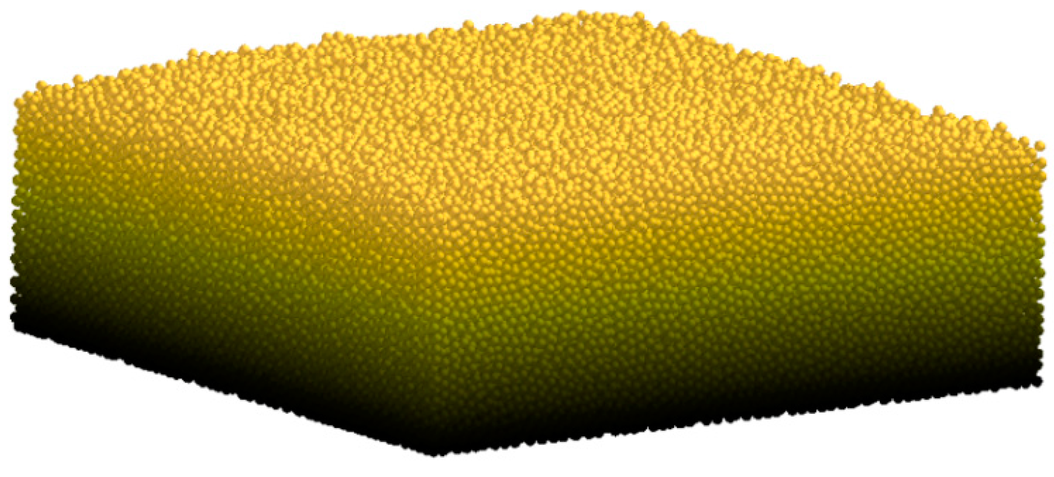
2.6.2. Soil Particle Model Construction

The soil model was established using EDEM 2020 software. Based on the crop agronomic requirements and the size of the furrowing and film-covering machine, the soil trough dimensions were set to 2000 mm × 600 mm × 400 mm (length × width × height). To simulate the characteristics of different soil particles in the solar greenhouse, three different soil particle models—single-ball, double-ball, and triple-ball—were used, all with radii of 1.5 mm. The contact model between soil particles adopted the Hertz–Mindlin with bonding contact model. The model was filled under the action of gravity. To enhance the bonding between particles, sedimentation was carried out after the first filling, and the filling was continued until the model was full. The details are shown in Figure 10 and Figure 11.

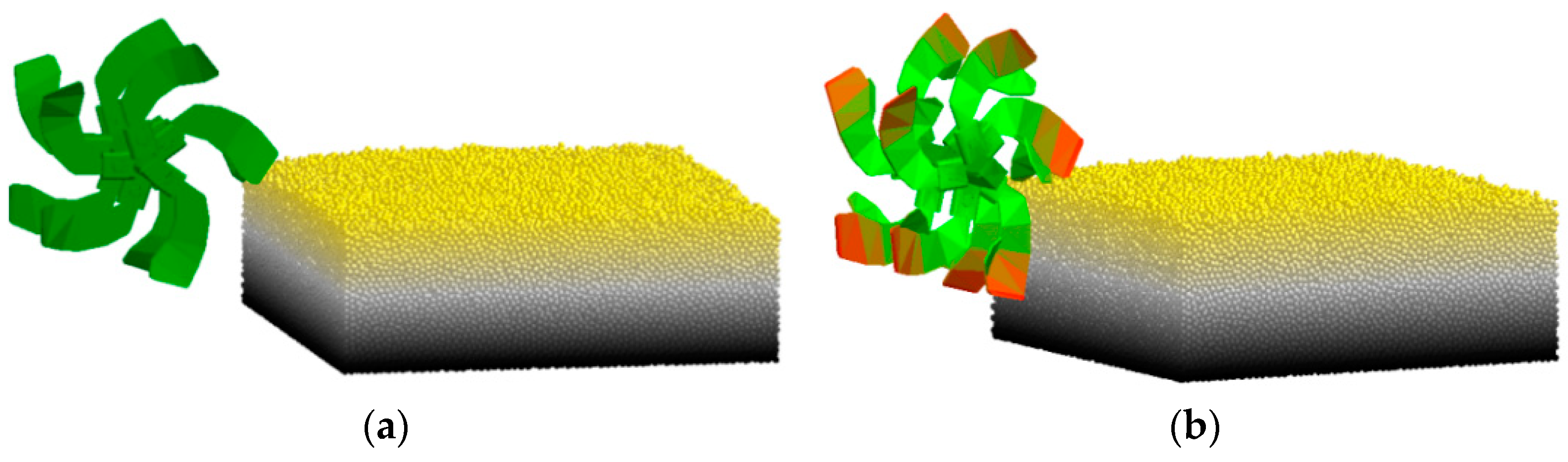
2.6.3. Ditching Knife Model Construction

To improve the efficiency of simulation calculations, the ditching cutter model was simplified by removing structures that did not affect the simulation results. Two ditching cutter models were established using SolidWorks 2023 and saved in STEP format for importation into EDEM 2020 software. In the preprocessing interface, the relative positions of the ditching cutter and the simulated soil were adjusted, and the forward speed and rotation speed around the cutter axis were added to the ditching cutter. The overall simulation model is shown in Figure 12.

2.6.4. Simulation Experiment Design

This study aims to evaluate the ditching performance of the ditching cutter by simulating its movement in the soil trench. The simulation process is shown in Figure 13. Based on design experience, when the field soil conditions remain unchanged, the ditching performance is primarily affected by three factors: forward speed (A), cutter shaft speed (B), and ditching depth (C). Therefore, a three-factor, three-level orthogonal experiment was designed, with the trench depth qualification rate (Y1) and power consumption (Y2) as indicators, using the L9 (3^3) orthogonal table arrangement. The experimental factor levels are listed in Table 2. To perform variance analysis and range analysis on the experimental data, the effect size of each experimental indicator and the optimal combination of factor levels were obtained using SPSS27 software.
The ditching process is crucial for forming the final trench characteristics. To study the influence of different experimental factors on trench stability, the trench section was fitted during the simulation process and presented using marked grid coordinate points. The trench profile curves of different ditching cutters under each experimental factor were drawn. The backfill depth and soil disturbance were analyzed, and the ditching stability and ditching width consistency coefficient of each group of simulation experiments with the combined ditching cutter were calculated.

2.7. Field Trial Design

2.7.1. Experimental Conditions and Materials

In September 2023, a field test of the ditching and film-covering machine was conducted in the test field of the Sixth Regiment of the First Division of the Xinjiang Production and Construction Corps. The soil in the test field was sandy, and soil conditions were consistent throughout the test. During the test, the temperature was approximately 21 °C and the relative humidity was 41%. The five-point test method was used to measure the firmness and moisture content of the soil at depths of 100 mm, 200 mm, and 300 mm. The specific data were as follows: At a depth of 100 mm, the average soil firmness was 142.3 and the moisture content was 11.4%. At a depth of 200 mm, the average soil firmness was 163.4 and the moisture content was 11.3%. At a depth of 300 mm, the average soil firmness was 187.6 and the moisture content was 11%. The equipment used in the test included a ditching and film-covering machine, a TYD-2 digital soil hardness meter, a TQ-660 dynamic torque sensor, a WQL-1-type traction force meter, a soil moisture meter, a steel tape measure, a steel ruler, and an electronic balance (Figure 14).

2.7.2. Ditching Power Consumption Test

The test method is based on the NY/T740-2003 “Quality of Field ditching Machinery Operation” standard. This test uses power consumption as an indicator to study the effects of the machine’s forward speed, the rotation speed of the ditching cutter, and the ditching depth on power consumption. In the field test, the machine’s operating speed and the cutter head rotation speed are determined according to the values in the table and are adjusted by the gear position and the throttle. The forward speed and cutter shaft rotation speed are adjusted by the gear position and the throttle, while the ditching depth is adjusted by changing the relative height of the depth-limiting wheel threaded rod and the fixed sleeve. Power consumption measurement collects the instantaneous torque of the cutter through a torque sensor (The model is TQ-660 dynamic torque sensor, developed by Beijing Shitong Kechuang Company, Beijing, China) and calculates the instantaneous power. To accurately measure the torque experienced by the ditching blade, the torque sensor is strategically positioned between the ditching blade and its drive shaft. After the test, the data processing terminal records the average power of the entire operation stroke. The data in the test factor table are combined to analyze the effects of various factors on ditching power consumption.

3. Results and Discussion

3.1. Simulation Test Results and Analysis

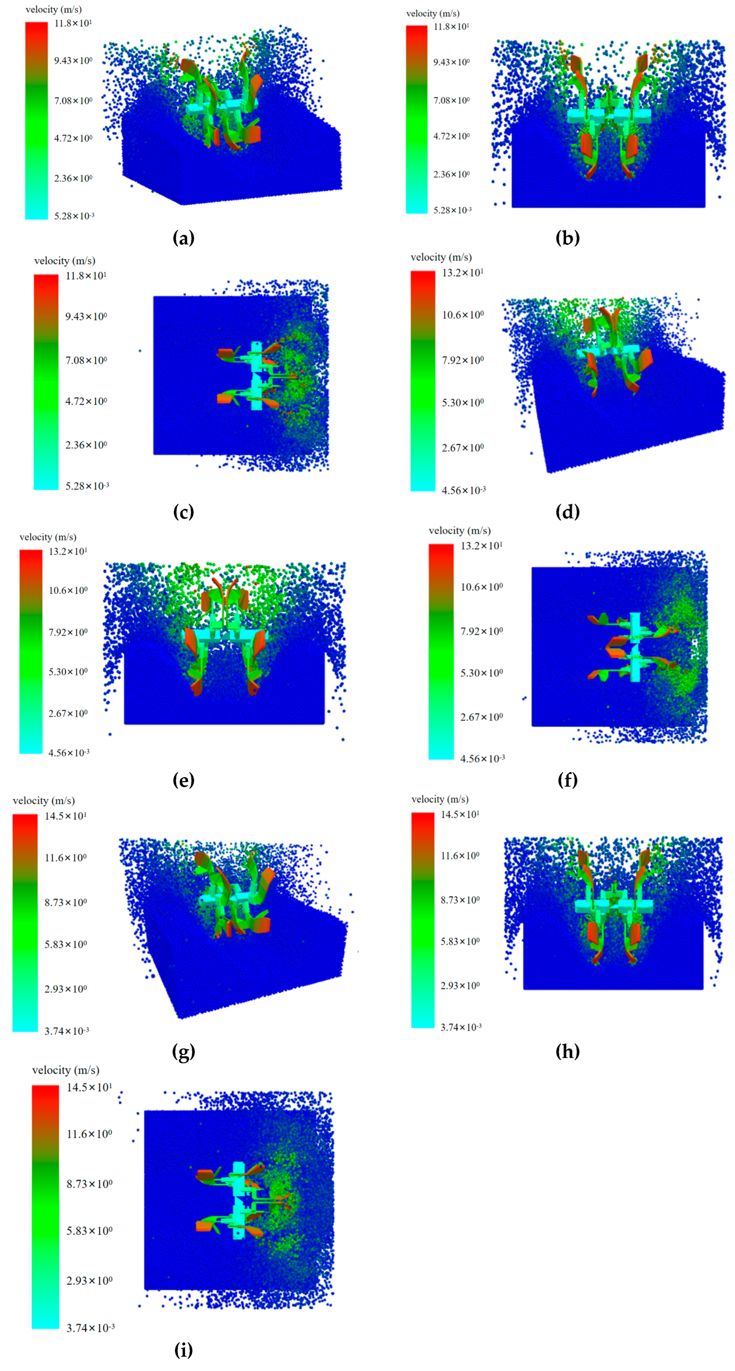
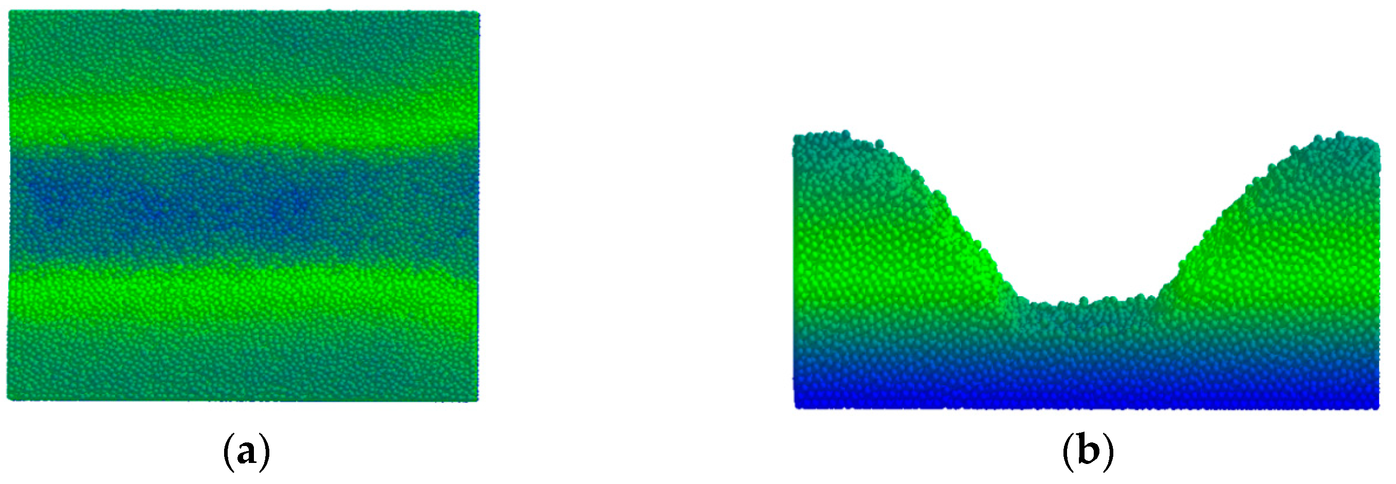
3.1.1. Simulation Groove Section Results and Analysis

This study employs the discrete element simulation (DES) method, focusing on the ditching process essential to the trench’s final configuration. To assess the impact of various experimental factors on trench stability, the simulated trench section is represented using marked grid coordinates. Subsequently, the profile curves of the trench under each experimental factor’s influence are depicted, as illustrated in Figure 15.
As the machine’s forward speed increases, the groove’s stability deteriorates. This instability primarily arises from the increasing inertial force of the soil due to higher speeds, causing uneven movement and soil accumulation. The single soil-cutting knife, which relies solely on a single cutting action, lacks mechanisms for multi-point support and pressure dispersion. Consequently, at high speeds, this can lead to significant soil disturbance, resulting in substantial soil particle accumulation on both sides of the groove and an irregular groove shape. In contrast, the throw-cut combined ditching knife disperses force more evenly through the concerted action of multiple blades. Its unique design minimizes soil displacement, thus effectively maintaining the groove’s stable shape.
As the rotation speed of the cutter shaft increases, the groove initially stabilizes. However, upon further increases, the groove becomes unstable again. At lower speeds, insufficient cutting energy from the blade fails to effectively separate the soil, leading to localized accumulation. When the rotation speed reaches a critical value, the cutting energy is optimal, facilitating uniform soil cutting and separation and thereby stabilizing the groove shape. Beyond this critical speed, excessive cutting force causes rapid soil ejection from the cutting point, leading to increased disturbance and subsequent instability of the groove shape. Nevertheless, the throw-cut combination ditching knife, through the synergistic effect of multiple blades, maintains the stability of the groove shape across a broader range of rotation speeds, displaying superior stability compared to the single soil-cutting knife.
With deeper ditching, the cutting force exerted on the soil increases, enhancing soil disturbance and displacement, which destabilizes the groove shape. Deeper ditching operations, compared to shallow ones, result in greater vertical and horizontal soil displacement due to increased soil layer thickness. Under these conditions, both the throw-cut combination ditching knife and the single soil-cutting knife exhibit reduced stability as the trench depth increases. Despite this, the throw-cut combination ditching knife still demonstrates a higher performance advantage under most operating conditions.

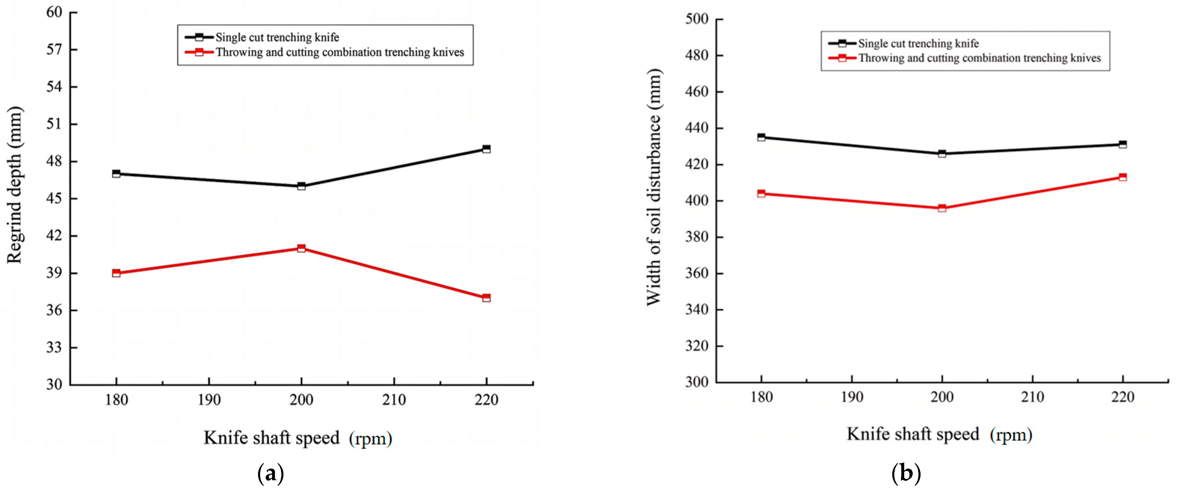
3.1.2. Analysis of Backfill Depth and Soil Disturbance

According to data analysis from Table 2 and Table 3, it is evident that maintaining a consistent forward speed while increasing the blade shaft speed leads to heightened soil disturbance by both the single soil-cutting knife and the throw-cut combined ditching knife, underscoring the significant impact of blade shaft speed on soil disturbance. At higher speeds, this increased soil disturbance adversely affects ditching quality. The single soil-cutting knife exhibits a maximum soil disturbance width of 435 mm and a backfilling depth of 49 mm. In contrast, the throw-cut combined ditching knife demonstrates better control, with a maximum soil disturbance width of 413 mm and a backfilling depth of 41 mm. This data suggests that the single soil-cutting knife causes more extensive soil disturbance during operation compared to the throw-cut combined ditching knife, which has narrower disturbance width and backfilling depth, indicating less soil disruption and better maintenance of trench integrity. The throw-cut combined ditching knife effectively disperses soil laterally during ditching, preventing soil from falling back into the trench—a critical factor in preserving the trench’s width and shape. Conversely, the design limitations of the single soil-cutting knife often result in soil being thrown back into the trench, leading to soil backflow and compromised trench shape.
The throw-cut combined ditching knife, with its dual functionality of cutting and throwing, exhibits superior resistance to soil disturbance. Its ditching performance and ability to control soil disturbance surpass that of the traditional single soil-cutting knife. This design significantly reduces soil disturbance width and backfill depth, enhances soil-throwing efficiency, and maintains a moderate trench bottom width. These attributes contribute to high-quality ditching outcomes and create a favorable planting environment, which is crucial for meeting the demands of embedded substrate cultivation. Thus, the throw-cut combined ditching knife represents a more optimal solution.
Origin2022 software facilitated the organization and plotting of data to analyze the impact of two different ditching knives on trench shape parameters. Figure 16 illustrates the comparative results of trench shape parameters achieved by these ditching knives under varying operational conditions.

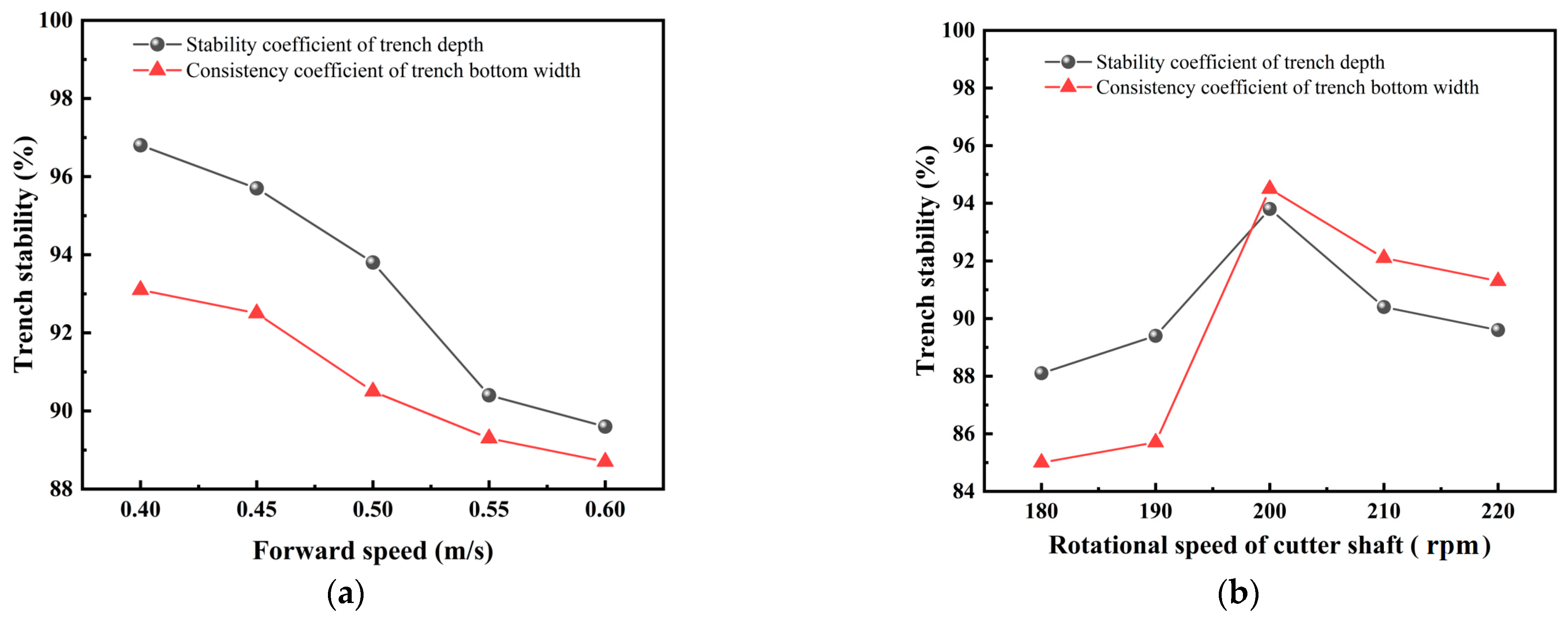
3.1.3. Analysis of Ditching Stability and Ditching Width Consistency Coefficient

The ditching depth stability and ditching width consistency coefficient for each group of simulation experiments with the combined ditching cutter were calculated, as shown in Figure 17.
Analysis of Figure 17a reveals that at lower forward speeds, the cutter achieves full contact with the soil, facilitating effective cutting while causing minimal and evenly distributed soil disturbance. However, as the forward speed increases from 0.4 m/s to 0.55 m/s, the soil force escalates, leading to an irregular groove shape and significantly reduced groove stability. Upon reaching a forward speed of 0.6 m/s, the inertial force exerted by the cutter on the soil heightens, accelerating the soil particles’ movement. This results in intensified rolling and irregular deposition of soil, and the reduced contact time between the cutter and soil fails to effectively counteract soil resistance, thus diminishing the groove’s stability. Nonetheless, at this speed, the groove width consistency remains at 88.5%. At this juncture, the soil is nearly in a balanced state, maintaining relative structural stability despite disturbances.
Analysis of Figure 17b indicates that at lower cutter shaft speeds, the cutter’s energy is insufficient to overcome soil cohesion, leading to uneven soil force and unstable groove structure. As the cutter shaft speed increases, the cutting efficiency improves, rapidly and uniformly separating the soil and stabilizing the groove structure. Groove stability incrementally enhances, peaking when the cutter shaft speed reaches 200 r/min, significantly improving the groove width consistency coefficient, with the ditching depth and groove width consistency exceeding 85%. However, beyond a cutter shaft speed of 210 r/min, the increased impact force and friction between the cutter and the soil cause significant secondary disturbances and displacement, decreasing the consistency of the groove depth and width and adversely affecting the groove’s overall stability.

3.1.4. Results and Analysis of Orthogonal Simulation Experiment on Ditching Knife

The power consumption of the ditching device mainly consists of two parts: the torque power required for the rotation of the cutter shaft and the traction power required for the ditching device to move forward. The sum of these two components represents the total power consumption of the ditching device. This study adopts the discrete element simulation method to numerically calculate and analyze the torque of the ditching cutter under different motion parameters.
The torque of the ditching cutter is simulated using EDEM 2020 software to study its power consumption characteristics. The built-in post-processing module, Analyst Tree 2020, of the software is used to export the torque and force data of the ditching cutter during the simulation process. The data acquisition interval is set to 0.1 s to ensure accuracy and continuity. Subsequently, the power consumption of the ditching cutter is calculated using the formula based on the set speed constant and the torque and force obtained from the simulation experiment.
In the simulation experiment, the motion trajectory of the ditching cutter in the soil groove is shown in Figure 18. The ditching cutter rotates around the cutter shaft and moves forward at a constant speed along the y-axis direction. To eliminate the non-steady-state effects before and after the ditching cutter enters and leaves the soil groove, only the time interval from the tool completely contacting the soil to leaving the soil is analyzed to reflect the actual working state of the ditching cutter. Figure 18 shows the ditching effect after the operation is completed.
The experimental results were analyzed using SPSS 2020 data processing software, as shown in Table 4 and Table 5.
According to the data analysis results in Table 4 and Table 5, the three test factors that affected the qualified rate of ditching were traction speed, ditching depth, and cutter shaft speed. Among these, the cutter shaft speed had the most significant impact on the experimental results. The importance of the test factors, in order of significance, was as follows: cutter shaft speed, forward speed, and ditching depth.

3.2. Field Trial Results and Analysis

In this study, we employed a three-factor, three-level experimental design to systematically assess the impact of varying operating conditions on the performance of a ditching machine. The design encompassed three principal factors: forward speed, cutter shaft speed, and ditching depth. The levels of forward speed were established at 0.4 m/s, 0.5 m/s, and 0.6 m/s. For cutter shaft speed, the levels were set at 180 rpm, 200 rpm, and 220 rpm. Lastly, the ditching depth levels were defined at 250 mm, 300 mm, and 350 mm.
The experimental plan and results are presented in Table 6.

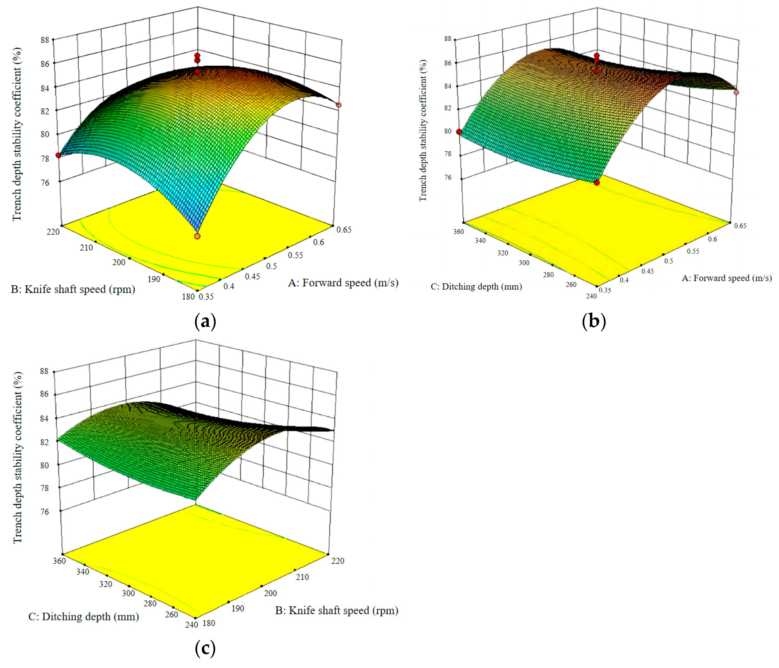
3.2.1. Response Surface Analysis

Design-Expert 13 was used to fit the test data, and the regression equation of the forward speed v, the blade shaft speed n, and the ditching depth h on the ditching power consumption p was obtained, as shown in Formula (24):
P = 0.6668 + 0.0101 A + 0.0129 B + 0.0288 C 1.48 A B 0.25 A C 0.75 B C 4.12 A 2 2.17 B 2 0.0155 C 2
The regression equation of the forward speed v, the cutter shaft speed n, and the ditching depth h on the trench depth stability s is shown in Formula (25):
S = 85.26 + 1.49 A 0.6875 B 0.475 C 1.48 A B 0.25 A C 0.75 B C 4.12 A 2 2.17 B 2 + 0.5075 C 2
In the formula, P is the power consumption of ditching, W; S is the stability of trench depth, %; A is the operating speed, m/s; B is the speed of the cutter shaft, rpm; and C is the ditching depth, mm.
To more clearly demonstrate the impacts of different experimental factors on the ditching power consumption and trench depth stability of the machine, we fitted quadratic regression model Equations (24) and (25) for ditching power consumption and trench depth stability. The response surface optimization model was then obtained, as shown in Figure 19 and Figure 20.
This study investigates the impact of machine forward speed and cutterhead speed on power consumption while maintaining a constant ditching depth. As demonstrated in Figure 19, when the ditching depth is kept constant, increases in both the forward speed of the machine and the cutterhead speed result in higher power consumption. Notably, the cutter shaft speed significantly influences the power consumption. An increase in forward speed elevates the number of soil particles cut and thrown per unit of time, enhancing the cutting resistance and friction and thereby raising the power consumption. Higher cutter shaft speeds increase the frequency of contact between the ditching cutter and the soil particles, cutting and throwing more soil particles and augmenting the adhesion and friction at the ditching cutter surface. These factors collectively escalate energy consumption during the cutting and throwing processes.
Figure 20 illustrates that, at lower forward and cutterhead speeds, the tool’s cutting effect on the soil is subdued and fewer soil particles are expelled from the ditch, leaving less residual soil at the bottom and enhancing ditch depth stability. At medium speeds, the cutting and throwing actions reach a balance, with the amounts of soil cut and thrown being relatively equal, resulting in a stable ditch depth structure with optimal ditch depth stability at this phase. As the forward speed and cutterhead speed further increase, the volume of cut soil exceeds that of thrown soil, accumulating more residual soil at the ditch bottom and diminishing the ditch depth stability. The intense inertial forces and kinetic energy from high-speed cutting cause soil particles to roll and deposit irregularly, affecting the flatness of the ditch bottom.
Through contour plots, response surface plots, interaction analysis between factors, and range analysis using the software, it was determined that the factors influencing power consumption rank as follows: cutter shaft speed > operating speed > ditching depth.
To achieve optimal ditch depth stability and minimize power consumption for ditch opening, in line with the agronomic requirements of embedded substrate cultivation, the following working parameters are recommended: operating speed: 0.5 m/s, cutter shaft speed: 200 rpm, and ditch opening depth: 300 mm. At these settings, the power consumption for ditch opening is 0.668 kW and the ditch depth stability is 86.7%. This parameter combination provides excellent trench depth stability and relatively low power consumption, meeting the operational requirements of ditching and mulching machines.

3.2.2. Ditching Performance Test and Results

This study’s experimental approach adheres closely to the standard guidelines outlined in “Quality of Field ditching Machinery Operation” (NY/T740-2003). It accurately calculates key performance indicators for the ditching and film-covering machine, such as ditching depth, depth stability, ditch surface width, ditch bottom width, and soil crushing rate post-ditching. The specific results are presented in Table 7.
The method for measuring the ditching depth is as follows: Before measurement, the soil at the bottom and around the ditch is cleared to ensure measurement accuracy. Two operational paths, each at least 50 m long, are selected. Along each path, five points are evenly spaced in the working direction for measuring the ditching depth, totaling ten measurement points. At each point, a ruler is placed at the intersection of the original surface and the two ditch walls. The ditching depth is then measured as the vertical distance from the center of the ditch bottom to the ruler.
Field tests measured and calculated the stability of the ditching depth and soil crushing rate. Data on the ditching depth, trench shape, trench surface width, and trench bottom width were collected, as shown in Table 7. The experimental results were compared with local agronomic requirements and relevant standards, leading to the following conclusions: The average ditching depth in the field test was 310 mm. The measurement results met the standards, with a small depth fluctuation range, demonstrating good stability and reliability of the ditching knife. The average ditching depth stability was 87.1%, exceeding the standard of 80.0%. This small depth variation is conducive to subsequent tillage and cultivation operations. The average trench surface width was 413 mm, and the trench bottom width was 304 mm. These dimensions enhanced soil drainage and aeration, improving the crop growth environment. The average soil crushing rate after ditching was 92.4%. This high soil crushing rate indicates that the trencher can fully crush the soil during operation, improving soil looseness, which benefits crop root growth and the penetration of water and fertilizer. It also reduces the difficulty and labor intensity of subsequent land preparation operations.
Additionally, a comparison between the simulation test results and field test results revealed high consistency under the same parameter conditions, verifying the accuracy of the simulation experiment. In summary, the ditching knife motion analysis and simulation method used in this paper are reliable and reasonable.

4. Conclusions

This study targets the unique soil conditions of the Gobi desert and saline–alkali lands in Northwest China by designing and optimizing a combined ditching knife suitable for yellow sand substrate cultivation in solar greenhouses, enhancing the efficiency of mechanized crop planting. The interaction between the soil and the soil-throwing piece was analyzed, and a dynamic equation was established to identify the key performance parameters of the machine. The main factors affecting the ditching performance were determined through simulations using EDEM 2020 software, and both prototype production and field testing were successfully conducted, providing a scientific foundation for mechanized planting in this environment.
  • The overall design of the ditching and film-covering machine and the optimization of its crucial component—the ditching knife—have enhanced the uniformity of soil-throwing and the stability of ditching depth. The optimized key dimensions of the ditching knife include an end height of the tangent surface at 65 mm, an inclination angle of 30°, a soil-throwing piece width of 120 mm, and a lateral width of soil throwing reaching 300 mm.
  • The improved structure of the ditching knife was validated by EDEM 2020 simulation analysis, demonstrating enhanced control over soil disturbance and reduced soil return depth in sandy soils, showcasing robust anti-disturbance capabilities. The optimal operating parameters for the ditching knife were set as: operating speed of 0.5 m/s, knife shaft speed of 200 rpm, ditching depth of 300 mm, ditching power consumption of 0.668 kW, and trench depth stability of 86.7%.
  • Field test results confirmed the accuracy of the simulation model and the machine’s operational performance. The tests revealed an average ditching depth of 310 mm, a trench surface width of 413 mm, a trench bottom width of 304 mm, and a post-ditching soil crushing rate of 92.4%, all meeting or surpassing national agricultural mechanization standards.
The ditching and film-covering machine developed in this study not only suits the specialized soil environment of Northwest China, but also markedly improves the efficiency and quality of mechanized operations by optimizing the components of the ditching knife. This provides crucial technical support for agricultural production in the region. Future research will continue to refine the furrow opening quality requirements for different crops and further adapt the equipment for broader agricultural applications.

Author Contributions

Conceptualization, Y.S., J.X. (Jiahui Xu), J.X. (Jianfei Xing), L.W. and W.L.; Methodology, Y.S., J.X. (Jianfei Xing) and X.W.; Software, Y.S. and C.H.; Validation, Y.S., J.X. (Jiahui Xu), L.W. and W.L.; Formal analysis, Y.S., J.X. (Jianfei Xing) and X.W.; Investigation, Y.S.; Resources, J.X. (Jiahui Xu); Data curation, Y.S. and J.X. (Jiahui Xu); Writing—original draft, Y.S. and C.H.; Writing—review & editing, Y.S., J.X. (Jianfei Xing), X.W., L.W. and W.L.; Supervision, X.W., C.H., L.W. and W.L. All authors have read and agreed to the published version of the manuscript.

Funding

This research was supported by the XPCC Science and Technology Plan Project (Grant No. 2023AB005-01), the Corps Science and Technology Talent Project (2024DB031) the Agriculture Bureau Project (Grant No. 2023AA304), the Tarim University President Fund Project (Grant No. TDZKSS202113), and the Vegetable Industry System (XJARS-07-25). We extend our heartfelt gratitude to these funding agencies for their generous support, which was crucial for the successful completion of our study.

Data Availability Statement

Data are contained within the article.

Acknowledgments

The authors would like to thank their schools and colleges, as well as the funding providers of the project. All support and assistance are sincerely appreciated.

Conflicts of Interest

The authors declare no conflicts of interest.

References

  1. Ahmed, Z.; Gui, D.; Murtaza, G.; Liu, Y.; Ali, S. An Overview of Smart Irrigation Management for Improving Water Productivity under Climate Change in Drylands. Agronomy 2023, 13, 2113. [Google Scholar] [CrossRef]
  2. Li, W.R. Analysis on agricultural ecological environment protection and agricultural sustainable development in Northwest China. Hebei Agric. 2024, 6, 41–42. [Google Scholar]
  3. Jiang, W.; Liu, J.; Zhao, X. Effects of saline drip irrigation on greenhouse tomato growth and yield under yellow sand cultivation mode. Acta Agric. Univ. Jiangxiensis 2024, 46, 356–366. [Google Scholar]
  4. Chen, Y.Y.; Luo, Y.J.; Shi, Z.X. Research on the development trend of soilless cultivation. Chin. Veg. 2023, 36, 139–148. [Google Scholar] [CrossRef]
  5. Savvas, D.; Giannothanasis, E.; Ntanasi, T.; Karavidas, I.; Ntatsi, G. State of the Art and New Technologies to Recycle the Fertigation Effluents in Closed Soilless Cropping Systems Aiming to Maximise Water and Nutrient Use Efficiency in Greenhouse Crops. Agronomy 2024, 14, 61. [Google Scholar] [CrossRef]
  6. Li, B.S.; Li, H.; Wang, Q.; Li, W.K.; Zhao, M.J.; Zhou, C.B. Effects of film covering on root zone temperature and growth of sweet pepper seedlings in ridge-embedded and furrow-embedded substrate cultivation in solar greenhouse. Shandong Agric. Sci. 2021, 6, 33–38. [Google Scholar] [CrossRef]
  7. Tan, Z.M.; Zheng, Y.; Shu, S.; Xiong, C.R.; Du, J.G.; Li, C.Y. Yellow sand soilless cultivation model of greenhouse tomatoes in southern Xinjiang. North. Hortic. 2020, 22, 166–169. [Google Scholar]
  8. Jiang, N.; Yang, Z.; Zhang, H.; Xu, J.; Li, C. Effect of Low Temperature on Photosynthetic Physiological Activity of Different Photoperiod Types of Strawberry Seedlings and Stress Diagnosis. Agronomy 2023, 13, 1321. [Google Scholar] [CrossRef]
  9. Guo, H.; Yao, L. Problems and countermeasures of high-quality development of Xinjiang vegetable industry under the background of rural revitalization. North. Hortic. 2024, 4, 129–136. [Google Scholar]
  10. Chen, Y.M.; Li, Z.G.; Zhang, W.B. Research progress and development strategies of mechanization of facility agriculture. Agric. Eng. 2022, 12, 22–24. [Google Scholar] [CrossRef]
  11. Sun, Z.Y. Analysis on the advantages of east-west planting of vegetables in solar greenhouse. Jiangsu Agric. Mech. 2021, 2, 14–16. [Google Scholar] [CrossRef]
  12. Li, J.; Li, H.; Chen, Y.; Lin, P.; Zhang, Q.; Cheng, Y.; Yang, Z.; Huang, G. Research on Ditching Mechanism of Self-Excited Vibration Ditching Machine. Agronomy 2023, 13, 905. [Google Scholar] [CrossRef]
  13. Chai, M.H. Comparative experiment report on mechanized trenching and fertilization for grape production management and maintenance in Yaodu District. Agric. Dev. Equip. 2024, 5, 145–147. [Google Scholar]
  14. Yang, X.; Wang, J.; Yang, J. Design and experiment of furrow opener for orchard furrow fertilization machine. J. Chin. Agric. Mech. 2023, 9, 36–42. [Google Scholar] [CrossRef]
  15. Liu, D.; Gong, Y.; Wang, G. Design and experiment of a compound operation machine for trenching, fertilization, mulching and soil covering in dry pond melon. Agric. Res. Arid Areas 2020, 5, 243–251. [Google Scholar]
  16. Liu, S.X.; Xu, C.B.; Zhang, H.J. Transactions of the Chinese Society for Agricultural Machinery Research status and development analysis of orchard basal fertilizer fertilization equipment. Trans. Chin. Soc. Agric. Mach. 2020, 2, 99–108. [Google Scholar]
  17. Nie, Y. Research status and development trend of orchard furrow fertilization machine. Agric. Sci. Technol. Equip. 2020, 5, 55–56. [Google Scholar] [CrossRef]
  18. Hamroqul, R. Parameters of the furrow cutter with levellers of the combined machine. E3S Web Conf. 2023, 390, 6–7. [Google Scholar] [CrossRef]
  19. Sukhbir, S.; Ashok, T.; Singh, A.K. Effect of Furrow Opener Design, Furrow Depth, Operating Speed on Soil Characteristics, Draft and Germination of Sugarcane. Sugar Tech 2016, 19, 476–484. [Google Scholar] [CrossRef]
  20. James, B.; Jack, D.; Mustafa, U.; John, M.F. Bentleg furrow opener performance analysis using the discrete element method. Biosyst. Eng. 2020, 189, 99–115. [Google Scholar] [CrossRef]
  21. Ravshanov, K.; Fayzullaev, K.; Ismoilov, I.; Irgashev, D.; Mamatov, S.; Mardonov, S. The machine for the preparation of the soil in sowing of plow crops under film. IOP Conf. Ser. Mater. Sci. Eng. 2020, 883, 23–25. [Google Scholar] [CrossRef]
  22. Neil, B.; Allan, J.; Gordon, O. Performance of hoe and triple disc furrow openers on no-till grain drills in a fine sandy loam soil. Soil Tillage Res. 2019, 195, 104–106. [Google Scholar] [CrossRef]
  23. Liu, P.Z.; Zhang, T.; Zhang, F.G.; Ren, X.L.; Chen, X.L.; Zhao, X.N. Ridge and furrow configuration improved grain yield by optimizing the soil hydrothermal environment and maize canopy traits in Northwest China. Plant Soil 2022, 499, 23–36. [Google Scholar] [CrossRef]
  24. Lei, X.; Yuan, Q.; Xu, T.; Qi, Y.; Zeng, J.; Huang, K.; Sun, Y.; Herbst, A.; Lyu, X. Technologies and Equipment of Mechanized Blossom Thinning in Orchards: A Review. Agronomy 2023, 13, 2753. [Google Scholar] [CrossRef]
  25. Aili, H.; Ying, C. Soil disturbance and draft force of selected seed openers. Soil Tillage Res. 2014, 140, 48–54. [Google Scholar] [CrossRef]
  26. Chen, X.G.; Zhang, Z.Q. Construction of agricultural production conditions, capital inflow to rural areas and modernization of agricultural production methods. Contemp. Econ. Res. 2024, 6, 86–94. [Google Scholar]
  27. Zeng, Y.; Jiang, X.; Wu, M. Development of a stratified cutting and throwing trenching cutter set for oil tea forest based on DEM-MBD. Trans. Chin. Soc. Agric. Eng. 2024, 8, 30–42. [Google Scholar]
  28. Liu, M.Z.; Xie, F.P.; Liu, D. Analysis and experiment on power consumption of reverse rotary trenching machine roller based on particle size effect. Trans. Chin. Soc. Agric. Eng. 2024, 7, 83–92. [Google Scholar]
  29. Chen, Y.F.; Liao, K.; Chen, F. Optimization design and experiment of forest trencher cutter. J. Chin. Agric. Mech. 2024, 3, 38–43. [Google Scholar] [CrossRef]
  30. Zhang, M.W.; Liu, H.Y. Design and research of a new rotary tillage, furrowing and fertilizing seeder. Agric. Mech. Res. 2024, 8, 120–124. [Google Scholar] [CrossRef]
  31. Cai, Y.C.; Gao, Q.M.; Luo, Y.Y. Design and experiment of self-propelled vegetable garden ditch fertilization machine. China Agric. Mach. Equip. 2023, 8, 70–73. [Google Scholar]
  32. Xu, C.B.; Wang, J.X.; Zhang, J.H.; Liu, S.X.; Quan, Z.; Zhang, C.F. Finite element simulation analysis of key structures of orchard double-row ditch fertilization machine. J. Agric. Mech. Res. 2022, 9, 12–13. [Google Scholar] [CrossRef]
  33. Shi, Y.L.; Chen, X.Y.; Chen, D.M.; Wang, D.W.; Shang, S.Q. Design and experiment of plowshare furrowing and ridging device for sweet potato ridging and shaping machine. Trans. Chin. Soc. Agric. Mach. 2022, 10, 16–25. [Google Scholar]
  34. Zhang, H.P.; Lin, C.; Chen, L.X.; Zhang, P.K.; Zheng, S.H. Design and experiment of a machine for trenching, fertilizing and covering soil in tea garden. J. Chin. Agric. Mech. 2022, 3, 28–35. [Google Scholar] [CrossRef]
  35. Wang, C.W.; Zou, K.; Xiao, H. Design and experiment of tobacco furrowing and soil-raising machine. China Agric. Mach. Equip. 2024, 1, 2–8. [Google Scholar]
  36. Li, X.J.; Li, L.H. Design and experiment of combined stubble-killing and seedling-strip rotary tillage machine. J. Chin. Agric. Mech. 2020, 8, 13–19. [Google Scholar] [CrossRef]
  37. Qin, K.; Liang, X.L.; Cao, M.C.; Ding, W.M.; Wu, Z.M.; Fang, L.F. Design and experiment of combined trenching knife for cutting and throwing in tea garden. Trans. Chin. Soc. Agric. Mach. 2021, 5, 74–82. [Google Scholar]
  38. Guo, H.; Sun, B.H.; Bi, Z.B. Design and experiment of hanging grape vine burying machine. Agric. Mech. Res. 2018, 12, 86–90. [Google Scholar] [CrossRef]
  39. Jia, Y.; Hu, J.; Li, Q.D. Simulation and experimental study of deep tillage shovel based on EDEM discrete element method. Chin. Agric. Mech. 2016, 4, 14–18. [Google Scholar] [CrossRef]
  40. Chen, H.X.; Qi, W.; Wang, J. Design of furrow opener based on discrete element method and response surface method. Mech. Des. 2023, 1, 65–71. [Google Scholar] [CrossRef]
  41. Yang, W.M.; Wu, B.; Peng, Z.; Tan, S.W. Evaluation of trenching quality of vertical spiral trencher based on discrete element method. J. Southwest Univ. 2019, 12, 1–7. [Google Scholar] [CrossRef]
Figure 1. Embedded substrate cultivation model.
Agronomy 14 01704 g001
Figure 2. Comprehensive structural diagram of the ditching and film-covering machine. Note: 1. Guide and depth-limiting device, 2. trench opener, 3. upper retaining plate, 4. side retaining plate, 5. driving wheel, 6. engine, 7. frame, 8. film frame, 9. suppression device, 10. suppression roller, 11. multi-link regulating mechanism, 12. walking wheel, 13. film pressing wheel, 14. earth-covering disc, 15. winch, 16. matrix box, 17. gear adjustment lever, 18. joystick.
Agronomy 14 01704 g002
Figure 3. Schematic diagram of single soil-cutting ditching knife.
Agronomy 14 01704 g003
Figure 4. Schematic diagram of the optimized throwing and cutting combined ditching knife structure.
Agronomy 14 01704 g004
Figure 5. Schematic diagram of the end height of the tangent surface of the thrower. Note: 1. Knife handle, 2. lateral view coordinates of the lateral cut, 3. chipper, 4. orthotopic lateral view coordinates, 5. tangent Section, 6. orthotropic end face height, 7. orthotropic lateral projection, 8. tangent blade, 9. chipper, 10. lateral section, 11. side cutting edge.
Agronomy 14 01704 g005
Figure 6. Schematic diagram of soil cutter movement.
Agronomy 14 01704 g006
Figure 7. Effect of λ value on the motion trajectory of ditching cutter.
Agronomy 14 01704 g007
Figure 8. Analysis of the soil-throwing process.
Agronomy 14 01704 g008
Figure 9. Schematic diagram of soil forces on the soil-throwing piece.
Agronomy 14 01704 g009
Figure 10. Particle shape.
Agronomy 14 01704 g010
Figure 11. Simulation test soil trough.
Agronomy 14 01704 g011
Figure 12. Schematic diagram of the overall simulation model. Note: (a) Overall simulation model of a single soil-cutting knife. (b) Overall simulation model of combined ditching cutter.
Agronomy 14 01704 g012
Figure 13. Simulated running process of ditching knife under various operating conditions. Note: (a) v = 0.4 m/s, cutter n = 180 rpm, trench depth 300 mm; (b) v = 0.4 m/s, cutter n = 200 rpm, trench depth 300 mm; (c) v = 0.4 m/s, cutter n = 220 rpm, trench depth 300 mm; (d) v = 0.5 m/s, cutter n = 180 rpm, trench depth 300 mm; (e) v = 0.5 m/s, cutter n = 200 rpm, trench depth 300 mm; (f) v = 0.5 m/s, cutter n = 220 rpm, trench depth 300 mm; (g) v = 0.6 m/s, cutter n = 180 rpm, trench depth 300 mm; (h) v = 0.6 m/s, cutter n = 200 rpm, trench depth 300 mm; (i) v = 0.6 m/s, cutter n = 220 rpm, trench depth 300 mm.
Agronomy 14 01704 g013
Figure 14. Field trial of an integrated embedded substrate-furrowing and mulching machine.
Agronomy 14 01704 g014
Figure 15. Effects of test factors on furrow type and furrow ridge. Note: (a) v = 0.4 m/s, N = 200 rpm, L = 300 mm. (b) v = 0.5 m/s, N = 200 rpm, L = 300 mm. (c) v = 0.6 m/s, N = 200 rpm, L = 300 mm. (d) v = 0.4 m/s, N = 180 rpm, L = 300 mm. (e) v = 0.4 m/s, N = 200 rpm, L = 300 mm. (f) v = 0.4 m/s, N = 220 rpm, L = 300 mm. (g) v = 0.4 m/s, N = 200 rpm, L = 250 mm. (h) v = 0.4 m/s, N = 200 rpm, L = 300 mm. (i) v = 0.4 m/s, N = 200 rpm, L = 350 mm. (ac) Effect of forward speed on furrow type and furrow ridges; (df) effect of cutter shaft speed on furrow type and furrow ridges; (gi) effect of depth of furrow opening on furrow type. Black line is the profile of the furrow type furrow ridges of the throw-and-cut combined furrowing cutter, with the cross-section at the center point. Blue line—throw-cut combined ditching knife is the profile of ditch-type ditch ridge at 0.5 m from the center point. Green line—profile of a single cutter ditch ridge, section at the center point. Red line—single ditching knife for the profile of ditch-type ditch ridge at 0.5 m from the center point.
Agronomy 14 01704 g015
Figure 16. Comparison of parameters of groove shape formed by two groove cutters under different working conditions. Note: (a) Backfill depth comparison. (b) Comparison of soil disturbance width.
Agronomy 14 01704 g016
Figure 17. Stability of ditching depth and consistency coefficient of ditching width under different working conditions. Note: (a) As the forward speed increases. (b) As the cutter shaft speed increases.
Agronomy 14 01704 g017
Figure 18. Ditching effect. (a) Edge throwing effect. (b) Muck in the bottom of a gully.
Agronomy 14 01704 g018
Figure 19. Response surface and contour plot of each factor on power consumption. Note: (a) A, B: interactive response surface and contour lines. (b) A, C: interaction response surface and contour lines. (c) B, C: interaction response surface and contour lines.
Agronomy 14 01704 g019
Figure 20. Response surface and contour map of each factor of trench depth stability. Note: (a) A, B: interactive response surface and contour lines. (b) A, C: interaction response surface and contour lines. (c) B, C: interaction response surface and contour lines.
Agronomy 14 01704 g020
Table 1. Simulation model parameters.
PropertyUnitValue
Soil trough L × W × Hmm2000 × 600 × 400
Forward speedm/s0.4–0.6
Rotational speed of cutter shaftrpm180–220
Soil densitykg/m31600
Poisson’s ratio for soil 0.35
Soil shear modulusPa1 × 106
Iron densitykg/m37860
Fe Poisson’s ratio 0.4
Shear modulus of FePa8 × 1010
Soil–soil recovery factor 0.6
Soil–Fe coefficient of recovery 0.5
Soil–soil static friction factor 0.4
Soil–Fe static friction factor 0.7
Soil–soil rolling friction factor 0.55
Soil–Fe rolling friction factor 0.05
Normal contact stiffness factorN·m−319,000
Tangential contact stiffness factorN·m−314,000
Critical normal stressKPa50
Critical tangential stressKPa30
Table 2. Key parameters of single soil cutter opener configuration.
Cutter Shaft Speed (rpm)Soil Disturbance Width (mm)Backfill Depth (mm)
18043547
20042646
22043149
Table 3. Key parameters of the combined ditching knife configuration.
Cutter Shaft Speed (rpm)Soil Disturbance Width (mm)Backfill Depth (mm)
18040439
20039641
22041337
Table 4. Analysis of orthogonal experimental results.
Test NumberForward Speed A (m/s)Knife Shaft Speed B
(rpm)
Ditching Depth C
(mm)
Trench Depth Pass Rate Y1 (%)Total Power Y2 (W)
11 (0.4)1 (180)1 (250)97.6655
212 (200)2 (300)99.2515
313 (220)3 (350)97.8867
42 (0.5)1298.2972
522397.71008
623198.4892
73 (0.6)1396.31513
832197.31032
933298.11347
K1294.60292.10293.30
K2294.30294.20295.50
K3291.70294.30291.80
k198.2097.3797.77
k298.1098.0798.50
k397.2398.1097.27
Extremely poor R0.970.731.23
Optimum levelA1B3C2
Major and minor factorsB > A > C
Best combinationA1B2C1
Table 5. Results of orthogonal experiments.
NormSource of VariationSquare SumDegrees of FreedomMean SquareF-ValueSignificance
Trench depth pass rate (Y1)A2.06921.035129.3130.007
B1.02920.51464.3060.015
C2.30921.154144.3060.008
Errors0.01620.008
Aggregate5.4238
Power wastage
(Y2)
A573,889.82286,944.9168.1030.06
B72,673.88236,336.9424.4140.045
C114,297.9257,148.9533.6790.029
Errors3393.73621696.868
Aggregate764,255.38
Table 6. Pilot program and results.
Test NumberForward Speed (m/s)Knife Shaft Speed (rpm)Ditching Depth (mm)Total Power (KW)Trench Depth Pass Rate (%)
10.62203000.75178.6
20.52003000.66884.3
30.42003500.75180.2
40.51802500.61484.3
50.51803500.65784.6
60.52203500.69281.4
70.61803000.71682.6
80.41803000.71676.4
90.52003000.67785.4
100.52003000.65383.6
110.62003500.74282.4
120.42002500.64780.4
130.42203000.72678.3
140.52003000.66286.3
150.52003000.67486.7
160.52202500.63884.1
Table 7. Results of open furrow field trials.
Operational Performance
Indicators
UnitStandardExperimental
Measurements
Ditching depthmm≥300310
Ditching depth stability%≥80.087.1
Trench widthmm400413
Width of the trench bottommm300304
Rate of soil fragmentation after furrowing%≥5592.4
Disclaimer/Publisher’s Note: The statements, opinions and data contained in all publications are solely those of the individual author(s) and contributor(s) and not of MDPI and/or the editor(s). MDPI and/or the editor(s) disclaim responsibility for any injury to people or property resulting from any ideas, methods, instructions or products referred to in the content.

