Article

Design and Testing of a 2-DOF Adaptive Profiling Header for Forage Harvesters

1
College of Engineering, South China Agricultural University, Guangzhou 510642, China
2
Department of Cell and Developmental Biology, College of Life Sciences, Zhejiang University, Hangzhou 310058, China
3
College of Electronic Engineering, South China Agricultural University, Guangzhou 510642, China
*
Author to whom correspondence should be addressed.
Agronomy 2024, 14(9), 1909; https://doi.org/10.3390/agronomy14091909
Submission received: 4 August 2024 / Revised: 21 August 2024 / Accepted: 24 August 2024 / Published: 26 August 2024
(This article belongs to the Section Precision and Digital Agriculture)

Abstract

:
The existing forage harvester header cannot automatically adjust the height and inclination during operation, resulting in uneven stubble height of forage, which, in turn, affects the efficiency of harvesting and the quality of forage regeneration. To address this issue, this study conducted the design and experimentation of a 2-degrees-of-freedom (DOF) profiling header. Firstly, this study designed an adaptive profiling header with 2-DOF adjustment, which was realized by the height adjustment mechanism and the tilt angle adjustment mechanism. The relationship model between the profiling device and the attitude of the header was established so that the header can acquire ground undulation in real time through the angle sensor of the profiling device. In order to verify the rationality of the header design, a co-simulation model of ADAMS and MATLAB/Simulink was built, and the header attitude control system was designed based on the fuzzy PID algorithm. The co-simulation results show that the header height ( H ) is always kept around 150 mm during the forwarding process of the harvester, with a maximum error of 5.8 mm, and the average relative error ( R E H ) and root mean square error ( R M S E H ) were 1.4% and 2.6 mm, respectively, and the maximum error of the tilt angle ( γ ) of the header is 0.53° and the R M S E γ is 0.22°, which indicates that the header profiling mechanism can accurately reflect the undulation of the terrain and the header attitude control system has good robustness. Finally, the test platform was built and tested in a grassland. The test results show that the average height of the header is 149.8 mm, the maximum error is 7.5 mm, and the R E H and R M S E H are 3.4% and 5.3 mm, respectively. The average error of the header inclination is 0.34°, and the maximum error is 0.57°. The test results indicate that the header can realize the adaptive adjustment of height and inclination, and the control system has high precision, stability and reliability, meeting the demand of automatic regulation of header attitude of a forage harvester.

1. Introduction

According to agronomic standards, perennial forage grasses like Pennisetum require multiple mowings, and the stubble height must meet strict specifications [1,2]. Generally, the stubble height should be minimized without affecting the next stage or the second year’s growth, which requires the header to be able to adapt well to the undulating changes in the terrain. At present, during the forage harvesting operation, the header attitude still needs to be manually controlled, which is difficult to operate. However, with the increase in the speed of forage harvesting operations, the method of manually adjusting the header attitude parameters can no longer meet the current operation requirements [3,4,5]. In addition, China has a tradition of “not planting grass on good land”, which means that forage grass may be planted in mountainous and hilly areas with large ground undulations and many rocks [6]. Therefore, the header of the forage harvester should have a good profiling function, and be able to automatically adjust the height and inclination according to the terrain conditions during operation [7,8,9].
The height of the harvester header determines the stubble height, which is an important parameter in the harvester operation process [10,11,12]. Improper adjustment of the header height will cause a large amount of harvest loss. If the header is too high, the stubble height will increase, increasing the loss in the harvesting process and even affecting the subsequent sowing quality. If the header is too low, it is easy to cause the cutter to scrape the soil, reducing the service life of the header [13,14]. The key to adjusting the header height is how to measure the current actual height from the ground. The existing measurement methods are mainly divided into contact measurement and non-contact measurement [15,16]. Non-contact measurement measures the header height through ultrasonic, infrared, image, and other sensors [17,18]. Ultrasonic measurement has the characteristics of easy control and good directionality. It can play a role in relatively harsh harvesting operation environments, but it is easily disturbed by weeds and soil during implementation [19]. Measurement based on image processing methods utilizes computer vision and other means of picture acquisition and information processing of the target crop, and the processing results are used as the basis to control the header height, but the image quality is easily affected by the environment [20,21].
Contact measurement is a method of measuring header height by directly contacting the ground with a contoured mechanical structure and detecting ground undulations in real time [10,16,22]. However, this measurement method has many mechanical components, limited lifespan, and is easily disturbed by mud in the field. Xie et al. [23,24] established a dynamic model of the header and designed a linear quadratic regulator (LQR) optimal control algorithm to further improve the performance of the system. Most control methods, including the above studies, basically use sensors to collect the height difference between the center position of the header and the ground, and then dynamically adjust the header pitch height along the travel direction according to a certain control strategy. Ni et al. [10] used a linear fitting method to establish a mathematical model of soil compaction and compaction depth, determined a calculation model for adjusting the header height, and designed a harvesting platform floating control system. Field performance tests showed that the absolute error between the actual stubble height after harvesting and the set header height was less than 2 mm. Zhu et al. [25] developed a hydraulic profiling system for the header for hilly and mountainous areas to solve the problem of rigid connection of the folding mechanism. The feasibility of the hydraulic profiling scheme was verified by ADAMS-AMESim joint simulation technology. The results showed that the header could swing within the range of ±30° and the hydraulic profiling system could pass through 250 mm corrugated roads, enhancing the operation capability of the harvester in hilly and mountainous areas. Liu et al. [26] designed an adaptive profiling header that uses a contact profiling device to detect height and a fuzzy PID control algorithm to control the header’s attitude. Their experimental results showed that the profiling device can accurately sense changes in field terrain, and the average error of header height control is 6.75 mm, which meets the requirements for rice harvesting and use. Ruan et al. [27] designed an automatic height control system for the combine harvester’s header. In this system, there are profiling plates on both sides of the cutting table, which can detect the height of the two ends of the header from the ground. However, the header has only one degree of freedom and cannot adjust the inclination angle. Cheng et al. [28] established an experimental device based on the inclination measurement method to detect the header attitude relative to the ground. The header structure has two degrees of freedom and can control the height and left and right horizontal angles. However, the profiling wheel is located at the rear side of the header, which causes a problem of signal acquisition lag during operation.
In summary, researchers have extensively studied contact and non-contact methods for measuring the header height, but the adjustment of the header mostly only considers a single degree of freedom, that is, only adjusting the header height. In areas with large ground undulations, there is still a problem of uneven cutting height [8,28]. To this end, based on the requirements of the 14th Five-Year National Key R&D Program project “Creation and Application of Full-Process Intelligent Operation Equipment for Main Forage and Feed Production”, this paper takes the traditional header as a reference object and carries out the design and experiment of a 2-DOF profiling header. The main contributions of this paper are as follows:
(1)
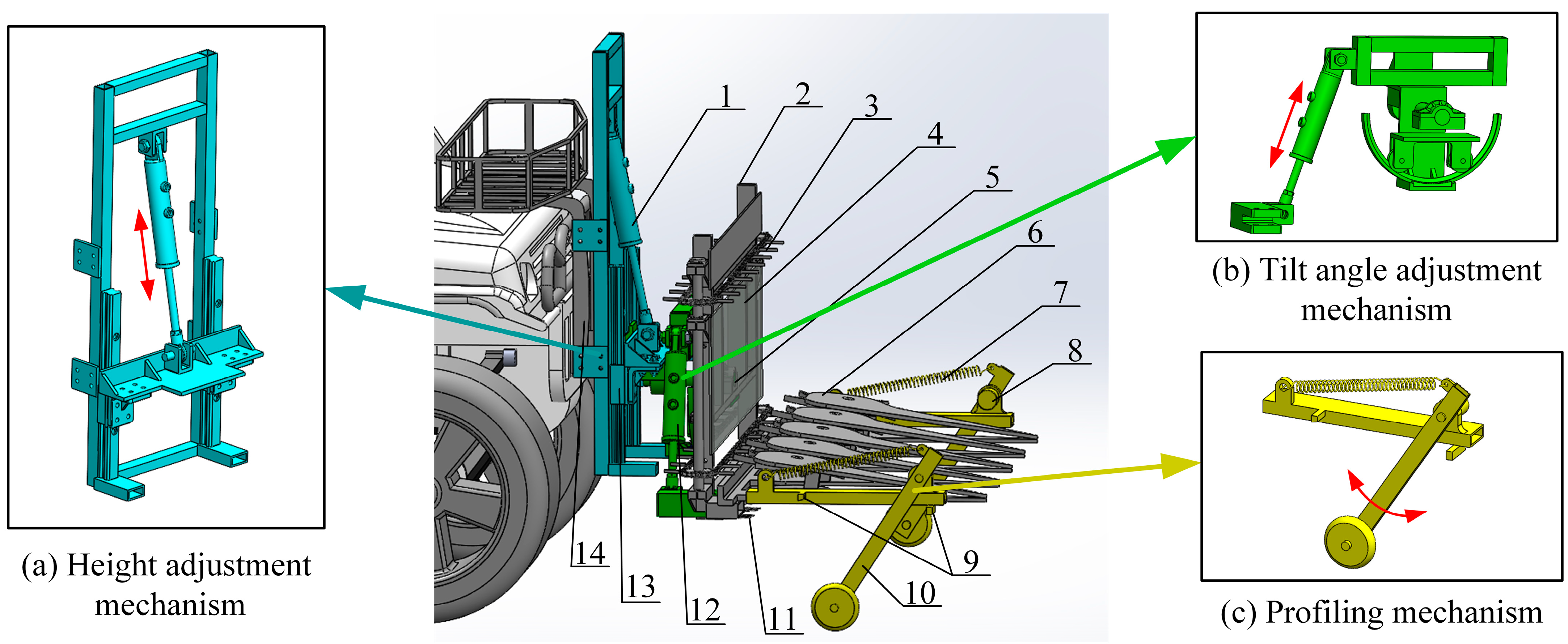
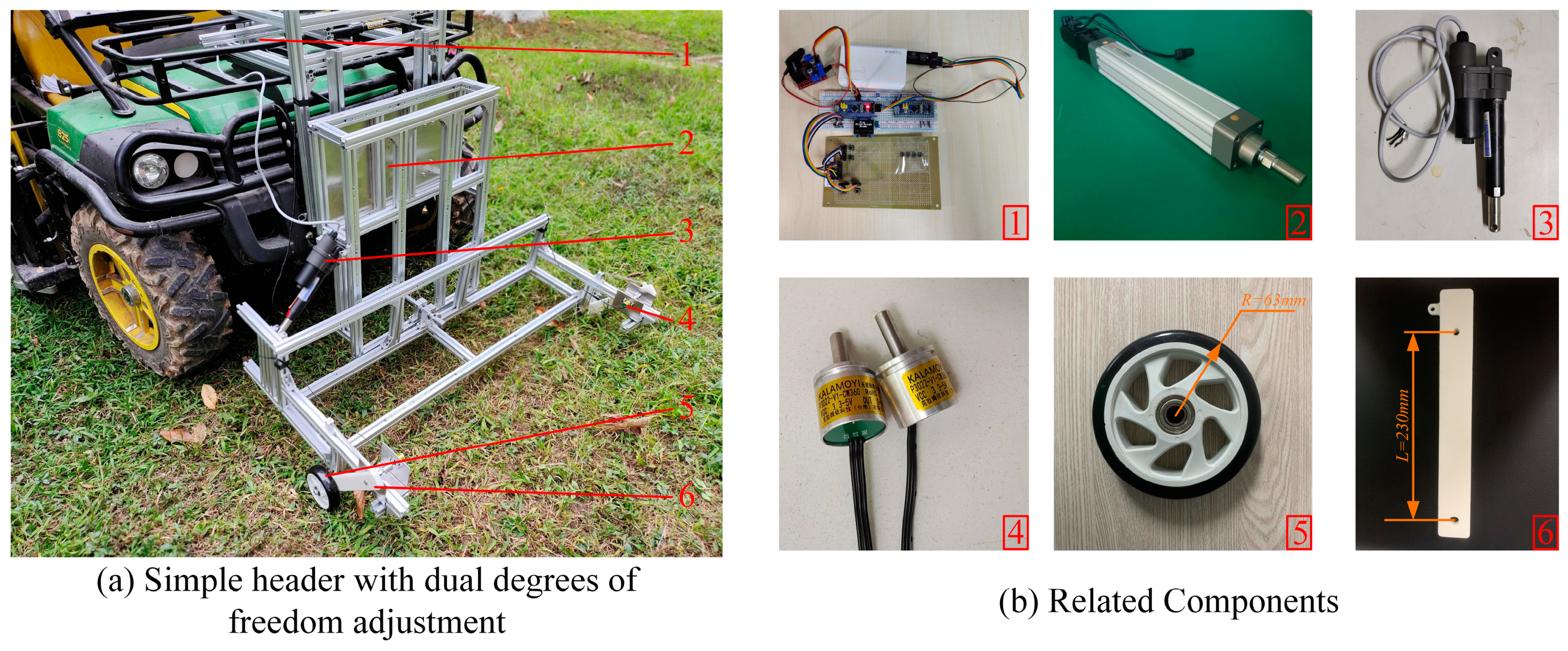
An adaptive profiling header with 2-DOF adjustment is designed. This header achieves 2-DOF adjustment through the height adjustment mechanism and the tilt adjustment mechanism.
(2)
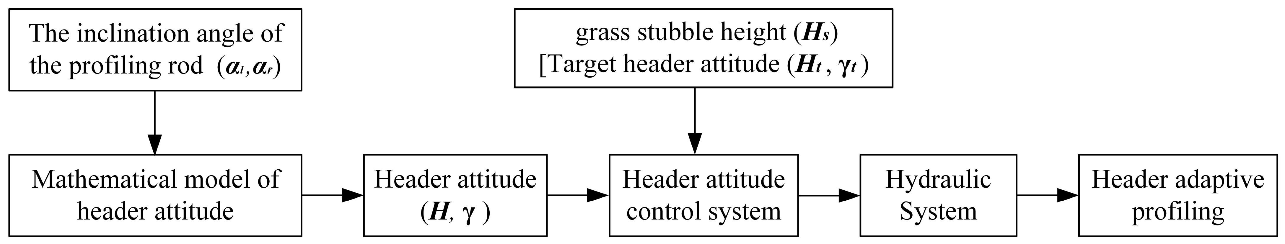
A relationship model between the profiling device and the header attitude is established. This model is the theoretical basis for the header attitude control strategy, which enables the system to detect terrain changes in real time.
(3)
A co-simulation model of ADAMS and MATLAB/Simulink was built, and the header attitude control system was designed based on the fuzzy PID algorithm. The co-simulation results verified the rationality of the mechanical design of the 2-DOF adjustment header, and the profiling mechanism can accurately reflect the undulating changes of the terrain.
(4)
A test platform was built and tested. The test results showed that the header can achieve adaptive adjustment of height and inclination, and the control system has high accuracy, stability, and reliability, which provides a reference for the design of the header attitude adaptive adjustment system of the forage harvester.

2. Materials and Methods

2.1. Design of 2-DOF Adjustment Mechanism for Header

The header of traditional forage harvesters cannot adjust the tilt angle, which makes it difficult to meet the requirements of forage harvesting in complex terrain in hilly and mountainous areas. To this end, this study proposes an innovative mechanical design scheme, which is to achieve 2-DOF adjustment of the header through a height adjustment mechanism and a tilt angle adjustment mechanism. This new type of header is essentially a 2-DOF spatial mechanism that can decompose the spatial movement of the header during operation into lifting movement on the longitudinal plane and rotational movement on the transverse plane. Compared with the traditional single-DOF header, the structure of this new type of header is relatively complex, but it is easy to establish a mathematical model and can accurately control its attitude.

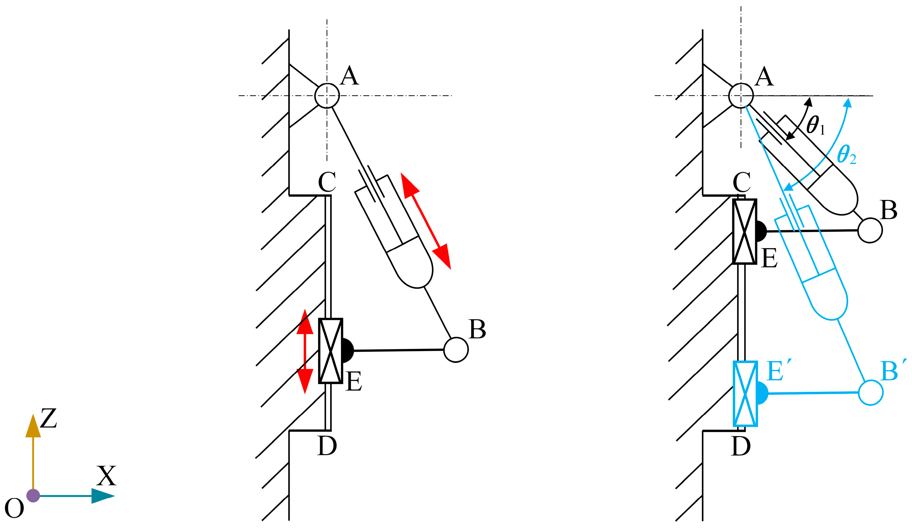
2.1.1. Height Adjustment Mechanism

Most harvester headers generally use a four-bar linkage for height adjustment. The design advantage of this mechanism is that the hydraulic cylinder is located in the middle of the four-bar linkage, so that a shorter hydraulic cylinder can achieve a wider range of height adjustment. However, the disadvantage of this mechanism is that in the four-bar linkage, the structure of the header is similar to that of a cantilever beam, which means that when the header needs to be finely adjusted in height, the control of the hydraulic cylinder must be extremely precise, which undoubtedly increases the difficulty of implementation. In contrast, the guide rail-slider mechanism shows superior performance in controlling the header height. The hydraulic cylinder can adjust the header height in an almost vertical direction, which is easier to achieve precise height control than the four-bar linkage. Therefore, in this study, we decided to use the guide rail-slider form as the height adjustment mechanism.
The adaptive profiling header is a symmetrical spatial mechanism. For the convenience of research, the height adjustment mechanism can be projected onto the longitudinal plane of the agricultural machinery body for analysis, which is approximately simplified to the plane motion of a rigid body [9]. In the longitudinal plane X O Z of the vehicle body, by simplifying the height adjustment mechanism of the header, the motion relationship of the structure is obtained, as shown in Figure 1.
As the length of the hydraulic cylinder changes, the header height also changes, and the range of the height adjustment mechanism is analyzed. When the header is at the highest point, the angle θ is the minimum value θ 1 , and when the header is at the lowest point, the angle θ is the maximum value θ 2 . As can be seen from the figure, A B is the total length of the height adjustment hydraulic cylinder, and the maximum range of the stroke is B B . Therefore, the calculation formulas for the total length of the height adjustment hydraulic cylinder and the maximum range of height adjustment are:
A B = B E c o s θ
B B = A B s i n θ 2 A B s i n θ 1

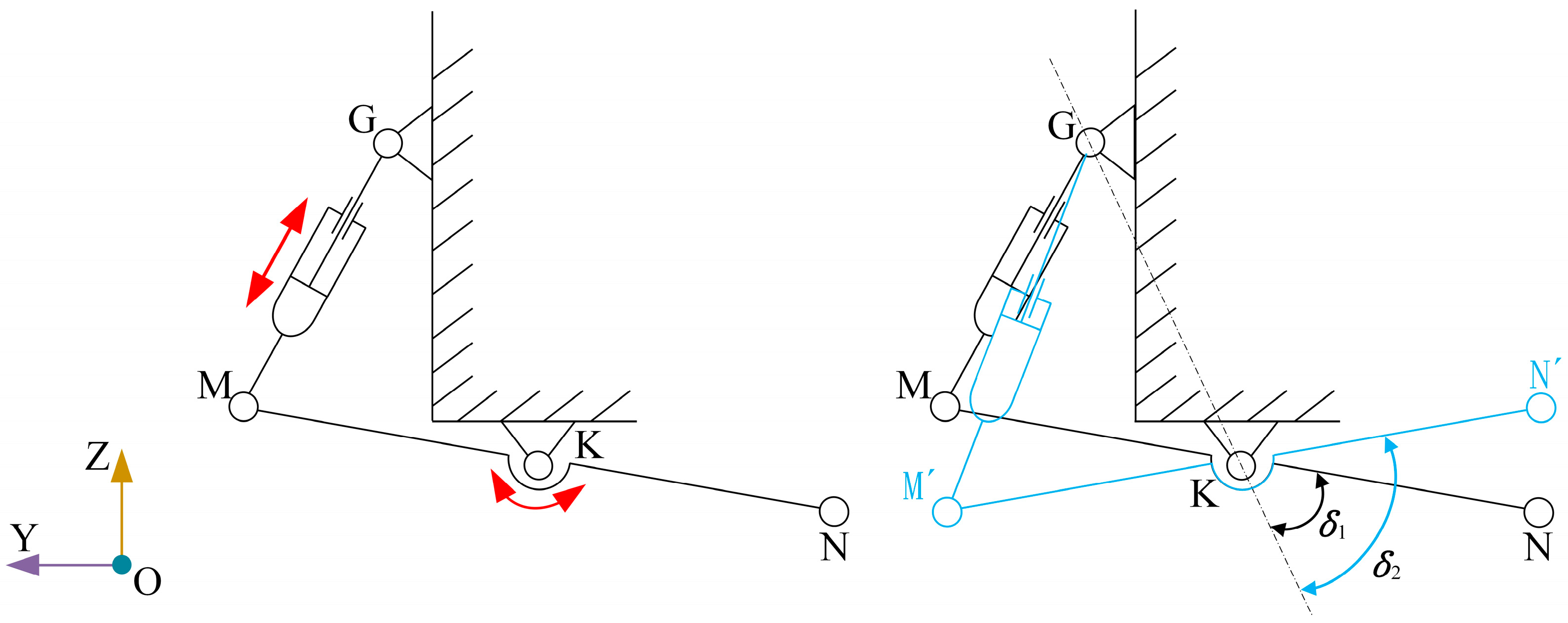
2.1.2. Tilt Angle Adjustment Mechanism

In order to clearly represent the tilt angle adjustment mechanism, the mechanism can be projected onto the positive plane of the agricultural machinery body for analysis, which can be approximately simplified into the plane motion of a rigid body [9]. In the longitudinal plane Y O Z of the vehicle body, by simplifying the tilt adjustment mechanism of the header, the motion relationship of the structure is obtained, as shown in Figure 2.
During the adjustment of the header, as the length of the hydraulic cylinder changes, the header’s inclination angle also changes. When the hydraulic cylinder is retracted to the limit, the header is in the left inclination limit position, and the angle δ between the header and the G K line has a minimum value of δ 1 . When the hydraulic cylinder is extended to the limit, the header is in the right inclination limit position, and the angle δ has a maximum value of δ 2 . As can be seen from the figure, the total length of the inclination adjustment hydraulic cylinder is G M , and its calculation formula is:
G M = G K 2 + M K 2 2 × | G K | × | M K | × c o s δ

2.2. Structural Design of the Header

2.2.1. 3D Model of the Header

The 2-DOF header is mainly composed of header connecting the frame, height adjustment mechanism, tilt angle adjustment mechanism, cutting deck, and profiling device, as shown in Figure 3. Among them, there is a profiling device on each side of the header, which is connected to the header in the form of a shaft connection. The change in the angle between the profiling rod and the ground reflects the height of each side of the header from the ground, and the difference between the angles reflects the left–right tilt of the header. In addition, the contact point between the profiling rod and the ground is always in front of the header, which eliminates the lag in the angle sensor data. The profiling rod installation point is above the cutter, and at the lowest point of the header, the front end is still at a certain height from the ground, which reduces the possibility of the front structure hitting the raised soil mound on the ground.
The profiling header has two degrees of freedom, and the height and inclination of the header can be adjusted simultaneously. The header height is controlled by the extension and retraction of the height adjustment hydraulic cylinder, which drives the middle platform to move up and down along the guide rail rigidly connected to the vehicle body, as shown in Figure 3a; the header’s inclination angle is controlled by the extension and retraction of the inclination adjustment hydraulic cylinder, and the front header rotates around the connection axis with the middle platform, as shown in Figure 3b. The profiling rods on both sides of the header can rotate around the connection axis, and the attitude data of the header can be obtained by the angle sensor installed on the profiling rod. The profiling mechanism is shown in Figure 3c. The main parameter settings of the header are shown in Table 1.

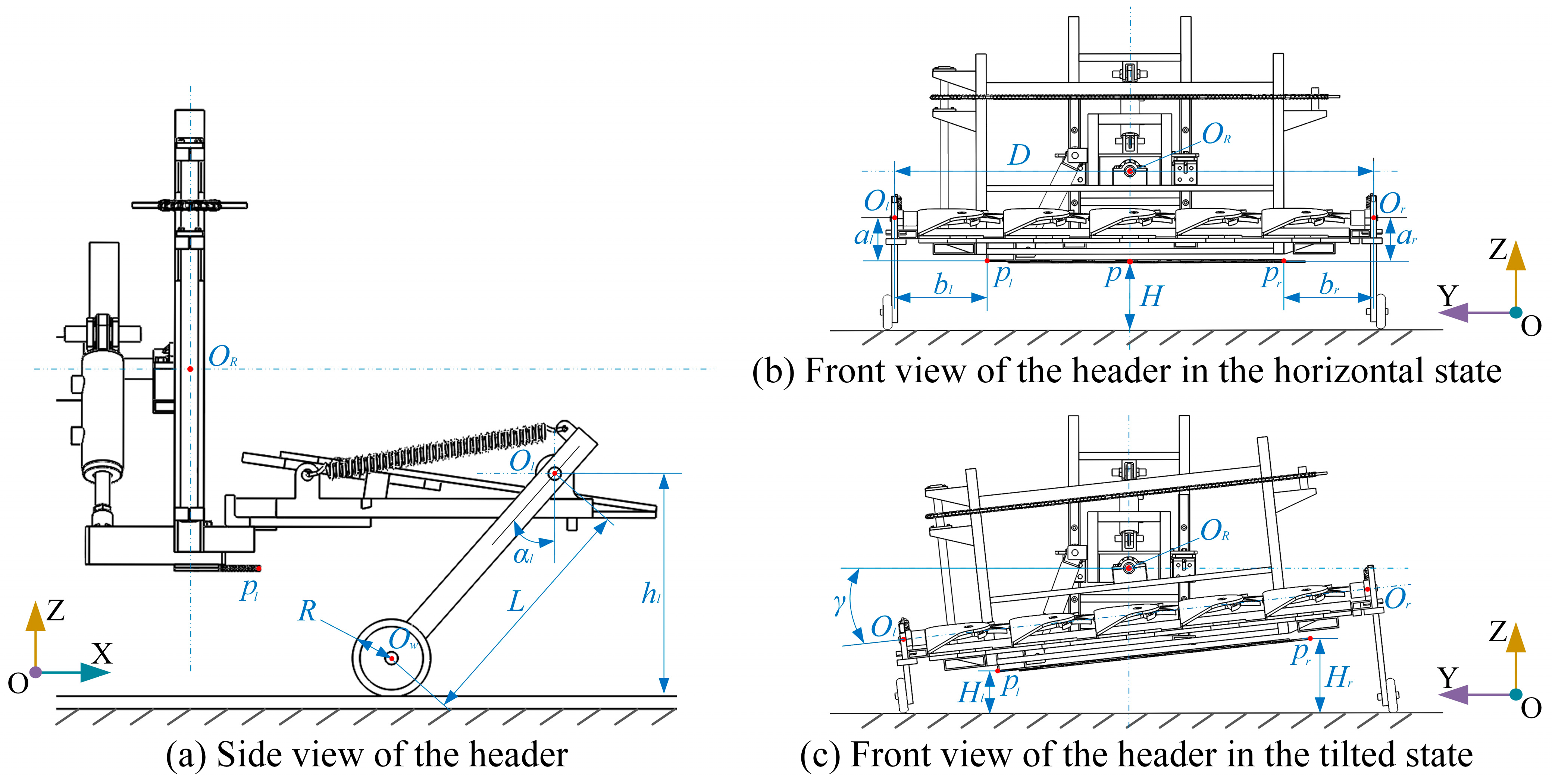
2.2.2. Relationship Model between Profiling Device and Header Attitude

According to the three-dimensional model of the header, a mathematical model of the header attitude and the profiling device is established. The purpose is to clarify the geometric relationship and motion law of each component, which can be used as a theoretical basis for determining the header attitude control strategy. The relationship between the profiling device and the header height H and the header inclination angle γ is shown in Figure 4. In this paper, the distances between the left and right endpoints ( p l , p r ) of the header and the ground are used as the ground heights ( H l , H r ) of the two sides of the header, and the deflection angles of the profiling rods on both sides of the header are α l and α r , respectively. When the absolute value of the angle difference between the profiling rods on the left and right sides | α l α r | is 0, the height difference ( H d ) on both sides of the header is 0 ( H = H l = H r ), which can be considered that the header is parallel to the ground ( γ = 0 ), and it is the most ideal working state of the header.
In order to obtain the height of the two sides of the header from the ground, first calculate the vertical distance between the rotation axis ( O l , O r ) of the two sides of the profiling rod and the ground; the formula is as follows:
h l = L cos α l + R
h r = L cos α r + R
where h l and h r are the heights of the rotation axis points O l and O r of the left and right side profiling rods from the ground, respectively. L represents the distance between the rotation axis of the profiling rod and the wheel axis O w , and R represents the radius of the profiling wheel, from which the header inclination angle can be obtained as follows:
γ = arctan h l h r D = arctan L D cos α l cos α r
where γ represents the lateral inclination angle between the header and the ground; D represents the distance between the rotation axis points ( O l , O r ) of the profiling rod.
Since the bottom of the header and the rotation axis of the profiling rod are not at the same horizontal height, the height of the rotation axis point of the profiling rod from the ground is not equal to the height of the header. Taking the left profiling rod as an example, it is known that the vertical distance between O l and the left end point p l of the bottom of the header is a l , and the horizontal distance is b l , then the vertical distance H l of point p l from the ground is:
H l = h l a l cos γ b l sin γ = L cos α l + R a l cos γ b l sin γ
Similarly, the vertical distance H r between the right point p r at the bottom of the header and the ground is:
H r = h r a r cos γ b r sin γ = L cos α r + R a r cos γ b r sin γ
In this study, the header is regarded as a rigid body, and the height of the midpoint p at the bottom of the header is defined as the header height H . Generally, the actual header height H is equal to the forage’s stubble height ( H s ), then:
H = H l + H r 2 = H s
In addition, this paper uses the height difference ( H d ) between the left and right sides of the header to represent the height difference between the stubble ( H s d ). The profiling system can keep the header parallel to the ground by directly controlling the size of H d , thereby ensuring the uniformity of the stubble height.
H s d = H d = H l H r
When H d = 0 , H = H l = H r , the header is parallel to the ground ( γ = 0 ), and the stubble height has the best uniformity ( H s d = 0 ).

2.3. Working Principle of Header Adaptive Adjustment

The header attitude adaptive adjustment system uses the angle sensor data of the profiling devices on both sides as the control input signal and adjusts the height and inclination in real time according to the actual situation of the header and the ground. During operation, the profiling device is always in contact with the ground under the action of tensile spring torque and its own gravity, and the ground fluctuation is converted to the actual heights of both sides of the header ( H l , H r ) by the angle sensors on the profiling device. According to Formulas (6)–(9), the actual height ( H ) and inclination ( γ ) of the header can be calculated, compared with the set value ( H t , γ t ), and the error is calculated and input into the system. The system controls the extension and contraction of the height adjustment hydraulic cylinder according to the set value to control the header height [29] so that the stubble height of the forage meets the requirements of the operation. On the slope section, the system adjusts the inclination hydraulic cylinder so that the absolute value of the height difference on the left and right sides of the header | H d | tends to 0, thereby keeping the header parallel to the ground ( γ = 0 ) to meet the requirement of uniform stubble height of the forage. The specific working principle of header height and inclination adaptive adjustment is shown in Figure 5.

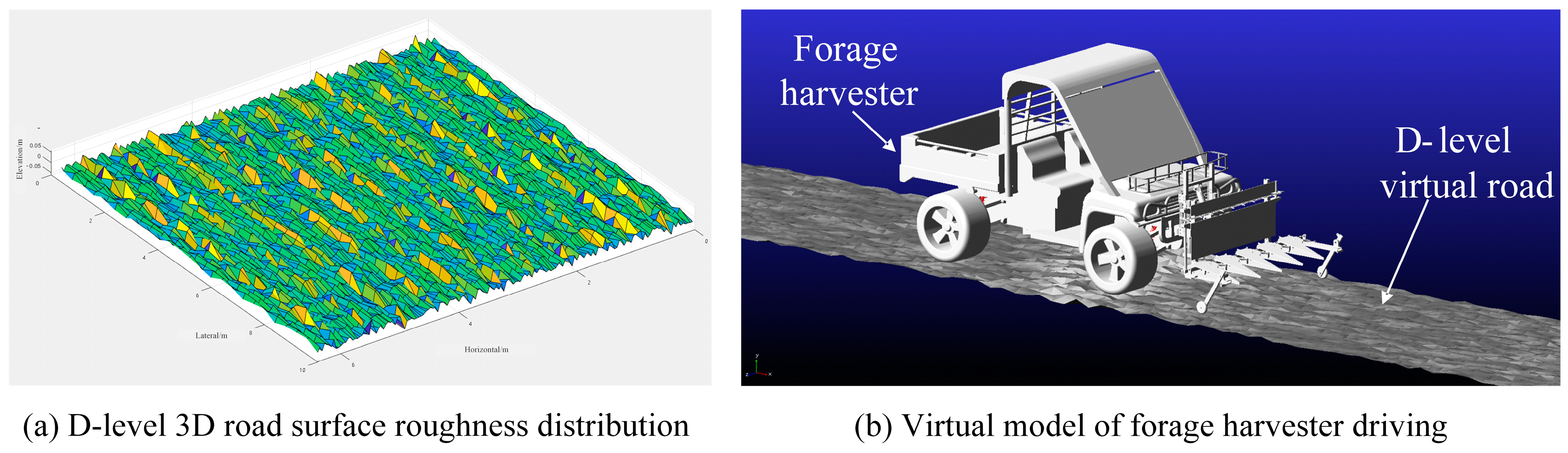
2.4. ADAMS and MATLAB/Simulink Co-Simulation Model

In order to verify the design rationality of the 2-DOF adaptive profiling header, this paper intends to use simulation technology to simulate the process of header control when the forage harvester is driving on the soil road. Before the co-simulation, the header model of Solidworks is first imported into the professional software ADAMS 2020 [30,31], and the dynamic model of agricultural machinery driving is established. Then, the header attitude control system based on the fuzzy PID algorithm is built in the MATLAB/Simulink [32] platform for co-simulation.

2.4.1. Virtual Road

When performing vehicle-level ADAMS dynamic simulation, it is necessary to establish a general model of the 3D road surface file to meet the simulation conditions of agricultural machinery under various working conditions. According to the road grading standard of GB 7031-2005 [33], the road surface in the forage growth environment is classified as a Class D Road surface. In order to meet the needs of ADAMS simulation road surface excitation, MATLAB is combined to generate the road surface based on the sine wave superposition method [34,35], and finally, a Class D three-dimensional spatial road surface spectrum file with a length of 100 m and a width of 20 m is obtained, which provides a realistic road surface input for the simulation of the forage harvester operation, as shown in Figure 6a. According to the road surface roughness data generated by MATLAB, MATLAB is used to write a triangular unit data matrix that can be recognized in ADAMS, and the road surface file (.rdf) is called out in ADAMS/View to obtain a three-dimensional virtual road surface. After multiple test experiments, it is proved that it can meet the simulation requirements of the road surface excitation of the virtual prototype of the forage harvester, as shown in Figure 6b. Finally, the header dynamics model is imported into ADAMS to establish the dynamics model of the forage harvester.

2.4.2. Design of Fuzzy PID Controller

Compared with traditional PID controllers, fuzzy PID controllers perform better in dealing with nonlinear, uncertain, and multivariable systems; have stronger adaptability and robustness [26], and have been successfully applied to many different disciplines, such as agriculture [36,37,38]. Fuzzy PID controller is a time-varying control system [4]. During the process of forage harvesting, the header attitude table changes uncertainly over time. Therefore, this study designed a fuzzy PID algorithm for header attitude control based on the relationship model between the profiling device and the header attitude and used the MATLAB/Simulink module to establish a fuzzy PID control simulation model. The fuzzy PID algorithm can realize the adaptive optimization of PID parameters by using fuzzy rules to adjust the controller parameters in real time, thereby effectively improving the dynamic response performance of the system [18,19].
The fuzzy inference controller realizes parameter adaptive optimization through three methods: fuzzification, fuzzy inference, and solving fuzzy. The principle is to fuzzify the input error e and the error change rate e c , perform fuzzy inference through a predefined fuzzy rule base, and obtain the fuzzy control output. Then the fuzzy output is defuzzified into a specific PID parameter adjustment value, and the PID parameters are dynamically adjusted to achieve adaptive control. Compared with traditional PID control, this adaptive tuning method enables the controller to adjust the three parameters K P , K I , K D in the PID controller online when facing various complex environments such as uneven roads, thereby adjusting the control amount of the header height and inclination, achieving a more flexible and robust control effect. The fuzzy PID control block diagram of the header adaptive adjustment system is shown in Figure 7.
In this study, the 2-DOF adjustment (height and inclination) of the header is adjusted by using the correction values of the three parameters of the PID controller ( Δ K P , Δ K I , and Δ K D ) as the output values of the fuzzy controller. In the header height adjustment control, the header height error e 1 and the height error change rate e c 1 are selected as the input variable values of the controller. The basic domains of e 1 and e c 1 are [−25 cm, 25 cm] and [−10 cm/s, 10 cm/s], respectively; the interval of Δ K P 1 is [−0.60, 0.60], the interval of Δ K I 1 is [−0.50, 0.50], and the interval of Δ K D 1 is [−0.35, 0.35]. Similarly, in the header inclination adjustment control, the header inclination error e 2 and the inclination error change rate e c 2 are selected as the input variable values of the controller. The basic domains of e 2 and e c 2 are [−10 cm, 10 cm] and [−20 cm/s, 20 cm/s], respectively; the interval of Δ K P 2 is [−0.30, 0.30], the interval of Δ K I 2 is [−0.10, 0.10], and the interval of Δ K D 2 is [−0.15, 0.15].
The variables of error e and error change rate e c are all fuzzy subsets of 7 levels, and the corresponding fuzzy language variable sets are [negative big, negative medium, negative small, zero, positive small, positive medium, positive big], respectively expressed as [NB, NM, NS, ZO, PS, PM, PB]. According to the PID parameter adjustment principle, combined with the actual adjustment process and experience of the header attitude of the forage harvester, the fuzzy control law is established, as shown in Table 2. In addition, in order to simplify the calculation process, the membership functions of e and e c are trigonometric functions. The principle of PID parameter self-tuning is as follows:
(1)
When the deviation is large, the response speed needs to be increased to eliminate the system deviation as soon as possible. At the same time, in order to avoid overshoot of the system response, the proportional coefficient K P should be increased, the differential coefficient K D should be reduced, and the integral coefficient K I is usually zero.
(2)
When the deviation and the deviation change rate are medium, K P needs to be reduced, and K D and K I take medium values to ensure the response speed of the system and reduce the overshoot of the system.
(3)
When the deviation is small, by increasing the values of K P and K I , the system has better steady-state performance. Considering the anti-interference ability of the system, in order to avoid overshoot and oscillation, K D should be appropriately selected.
(4)
When the deviation change rate is large, K P should be reduced and K I should be increased.

2.4.3. Co-Simulation Based on Fuzzy PID Control System

  • Construction of Co-Simulation System
The purpose of building the co-simulation model of ADAMS and MATLAB/Simulink is to verify the design rationality of the adaptive 2-DOF header by simulating the working process of the profiling device and its influence on the harvesting quality during the harvesting operation on the undulating road surface. Before the co-simulation, the harvester model designed in Solidworks is first imported into the ADAMS software, and the state variables related to the working state of the harvester are created in ADAMS. These variables will be used for data interaction with MATLAB/Simulink. Then, a header attitude control system based on the fuzzy PID algorithm is built in the MATLAB/Simulink platform for co-simulation. Among them, the header attitude is the variable output from ADAMS to MATLAB/Simulink, and the value of the hydraulic cylinder force solved by MATLAB/Simulink is the variable input from MATLAB to ADAMS. Add the above variables to the “ADAMS Controls” module, set the control software to MATLAB 2021b, and finally export the ADAMS model to Simulink format for co-simulation in Simulink. The co-simulation model is shown in Figure 8.
During the simulation, the profiling devices on the left and right sides of the header move with the ground, and the angle sensor outputs signals in real time. The system can obtain the height data of both sides of the header relative to the ground in real time through the relationship model between the profiling device and the header attitude and adjust the header attitude in real time based on the information, thereby realizing the header profiling function.
b.
Evaluation Metrics
The adjustment accuracy of the header attitude is an important indicator for evaluating the header profiling effect. The higher the adjustment accuracy of the header, the more accurate the stubble height, and the better the yield and quality of forage in the regeneration season. In order to evaluate the control effect of the header during operation, this study compares the data of the header target posture and the actual posture and uses relative error ( R E ) and root mean square error ( R S M E ) as the measurement criteria. The relevant formula is as follows:
A E H = H i H t
R E H = A E H H t
R M S E H = 1 N ( H i H t ) 2 N           ( i = 1,2 , , N )
In the formula, A E H represents the absolute error of the header height, R E H represents the R E of the header height, R M S E H represents the R S M E of the header height, and N represents the number of samples. Similarly, the evaluation index of the header inclination angle is also evaluated using the R E γ and the R M S E γ . The specific formula is as follows:
A E γ = γ γ t
In the formula, A E γ is the absolute error of the header inclination, γ t is the target inclination set by the header, and γ t generally set to 0. Therefore, this study uses the absolute error A E γ of the inclination instead of its R E γ , that is:
R E γ = A E γ = γ
R M S E γ = 1 N ( γ i ) 2 N           ( i = 1,2 , , N )
c.
Co-Simulation Results and Analysis
According to the DB5117/T 97-2024 Pennisetum harvesting standard [39,40], the optimal stubble height ( H s ) for mechanical harvesting of Pennisetum is 100~200 mm, and the stubble height error ( E h s ) does not exceed 10%. Therefore, in this study, the target value of the header height ( H t ) is set to 150 mm and the target value of the header inclination angle γ t is set to 0°.
In ADAMS, the harvester is set to run on a virtual D-level road, and the speed is set to 3 km/h. In Simulink, the joint simulation time is set to 5 s, the step size is a fixed step size, and the data interaction cycle is 1 ms. The initial height value of both sides of the header is set to 150 mm, and the height of the header during operation is output after the simulation starts. The results of the co-simulation are shown in Figure 9.
The results of the joint simulation show that the attitude of the header can be adaptively adjusted according to the changes in the terrain during the movement. Among them, the header height is always maintained at about 150 mm, with an average error of 2.1 mm, a maximum error of 5.8 mm, and R M S E H of 2.6 mm; the average error of the header inclination is 0.18°, the maximum error is 0.53°, and R M S E γ is 0.22°. These results show that during the entire movement of the header, not only is the height control effect good and the deviation small, but it can also maintain a high level of accuracy, can effectively adapt to terrain changes, and ensure the working stability and accuracy of the header.
The results of the simulation test confirm that the mechanical structure of the 2-DOF adaptive profiling header designed in this study is reasonable and can accurately reflect the undulating conditions of the ground, and the regulation of the height and inclination of the header meets the predetermined test standards and has certain stability and anti-interference ability.

3. Experimental Testing and Analysis

3.1. Test Platform Construction

In order to verify the actual profiling effect of the 2-DOF header, this study built a simple header on the John Deere 825i all-terrain vehicle, as shown in Figure 10a. The relevant components are shown in Figure 10b, where 1 is the ST32 controller (STM32F103C8T6), 2 is the height adjustment device, 3 is the tilt adjustment device, 4 is the angle sensor, 5 is the profiling wheel, and 6 is the profiling rod. It is worth noting that the angle sensor used in this test platform is the P3022-V1-CW360 sensor of PandAuto, with a resolution of 360°/4096 (12 bits) ≈ 0.088°, and the sampling frequency is set to 1000 HZ. It can perform 360° measurement and output a voltage signal of 0~5 V, which meets the needs of the deflection angle measurement of the profiling device.

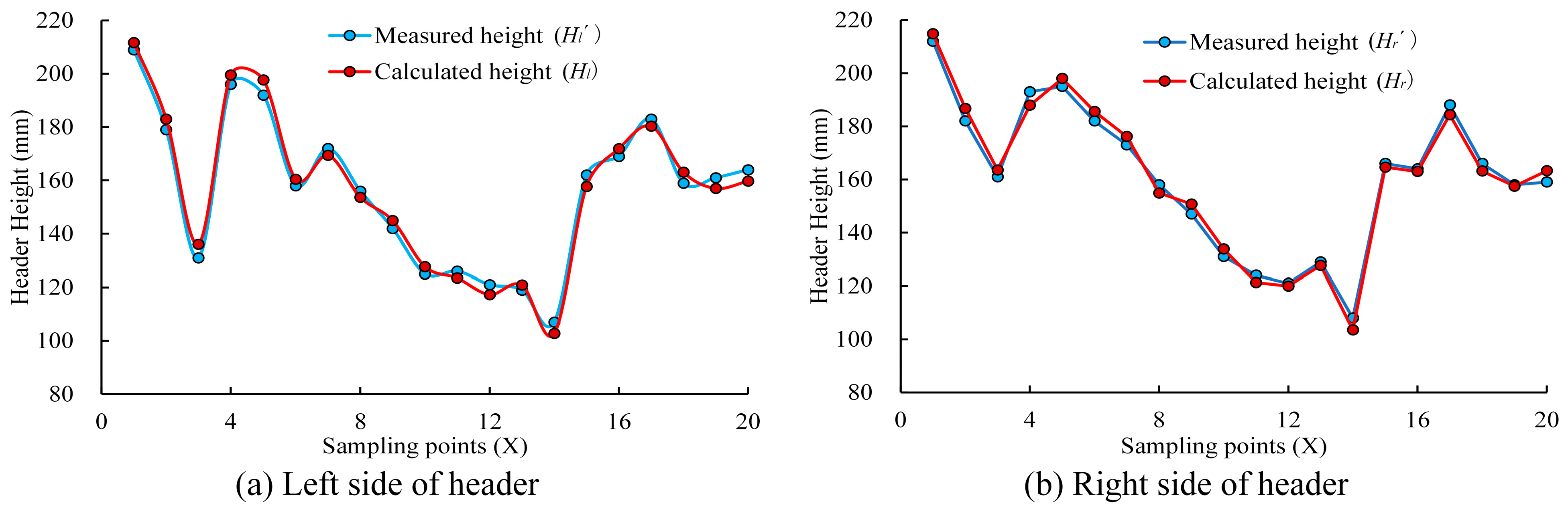
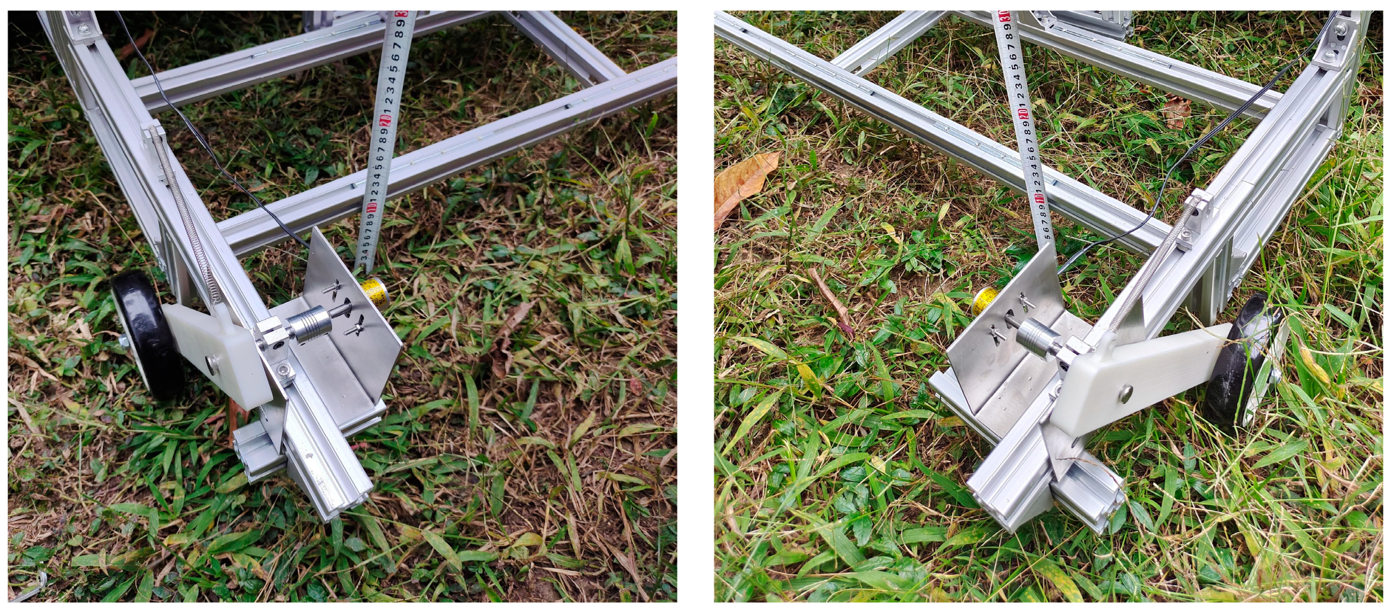
3.2. Calibration of Header Profiling Device

Since the inclination adjustment mechanism of the header is asymmetrically designed and there are combined errors during the installation process, this may directly affect the profiling effect of the header. Therefore, after the header is installed, the profiling device must be calibrated first to ensure the accuracy of the data. During the calibration of the header profiling device, the header is adjusted to a specific attitude, and the heights of the header from the ground on both sides ( H l , H r ) are measured and recorded using a ruler. Then, the corresponding angle sensor data is recorded and the heights of the header from the ground on both sides ( H l , H r ) are calculated according to Formulas (7) and (8). Finally, check whether the measured value and the calculated value are consistent. Repeat the adjustment of the header attitude, measure a total of 20 sets of data, and compare the calculated header height with the actual header height data measured by the tape measure (Figure 11). The relevant results are shown in Table 3. It is worth noting that if the data deviation is large, the profiling device needs to be adjusted and recalibrated.
The results show that the maximum error between the calculated height and the measured height of the left header is 5.7 mm, the average error is 3.4 mm, the relative error is 2.25%, the correlation coefficient is 0.993, and the two curves are highly correlated; the maximum error between the calculated height and the measured height of the right header is 5.1 mm, the average error is 2.9 mm, the relative error is 1.83%, the correlation coefficient is 0.994, and the two curves are highly correlated. The calibration results in Table 3 and Figure 11 verify the accuracy of the profiling device and the mathematical model of the header attitude and also show that the profiling mechanism can accurately reflect the undulating changes of the terrain.

3.3. Header Attitude Adjustment Test

The adjustment accuracy of the header attitude is an important indicator for evaluating the header adaptive profiling control system. The higher the adjustment accuracy of the header attitude, the more accurate the stubble height of the forage and the better the yield and quality in the regeneration season. Therefore, in order to further verify the performance, reliability. and control accuracy of the 2-DOF adaptive header profiling system, an experiment was carried out in May 2024 at the School of Engineering of South China Agricultural University in Tianhe District, Guangzhou City, Guangdong Province.
When the harvester is driving on the grass, the profiling device is always in contact with the ground under the action of the tension spring torque and its own gravity. The angle sensor detects the angle change of the profiling device and converts the ground fluctuations into the actual height of both sides of the header according to the relationship model between the profiling device and the header attitude so that the control system adjusts the header attitude in real time according to the information, thereby realizing the header profiling function. During the test, the driver only controls the speed and direction of the agricultural machine, and the control system automatically adjusts the header attitude. The actual ground height of both sides of the header is manually measured and recorded every 2–3 m when the machine is stopped, as shown in Figure 12.
Combined with the requirements of the stubble height of Pennisetum [35], the target value ( H t ) of the header height was set to 150 mm in the experiment, and the header height error ( E h ) should be less than 10% (15 mm). The relationship model between the profiling device and the header attitude showed that the left and right height difference ( H d ) of the header should be less than 30 mm, that is, the header inclination error ( E γ ) should be less than 1.43° to meet the stubble height accuracy requirements. The header was constantly changed during the experiment, and a total of 14 sets of data were collected. Finally, the measured values of the header attitude data were compared with the target values set in the system. The relevant results are shown in Table 4.
The actual height distribution of the header at different sampling points is shown in Figure 13a. According to the actual operation requirements, the error of the stubble height should be less than 15 mm, that is, the header’s height error should be controlled within the range of ±15 mm. It can be seen from the figure that when operating the synchronous profiling header, its height is all distributed within the allowable error range. By calculating the measurement data of the header height, it can be concluded that the average height of the header is 149.8 mm, the maximum error is 7.5 mm, the average R E H is 3.4%, and the R M S E H is 5.3 mm, which shows that the header profiling system can effectively control the header height. In addition, the average error of the header inclination is 0.34°, and the maximum error is 0.57°, which shows that the header is basically parallel to the ground during the operation, which can maintain the uniformity of the stubble height and meet the agronomic requirements of the stubble height of the forage harvesting operation.
During the test, there were weeds and clods of different sizes in the selected plots, and the test results showed that the system detection accuracy was relatively stable and was not affected by the above interference factors. The above test shows that during the operation, the 2-DOF header can achieve adaptive profiling and the control effect is ideal, with high control accuracy.

4. Discussion

As one of the various types of agricultural crop harvesters, the forage harvester has a more complex structure and a more special actual operating environment, so there are many factors that actually affect the harvester’s profiling effect. Therefore, the research content of this paper will be applied to the actual operation of forage harvesters in the future, and attempts will be made to extend it to various types of harvesters to carry out harvesting operations of various crops and expand the scope of application. In addition, response speed is also an important factor affecting the performance of the header attitude adaptive adjustment system [4,24,41]. Future research can start from optimizing the header mechanical structure, selecting appropriate control strategies, and replacing high-precision control components to improve system performance.

5. Conclusions

In view of the characteristics of forage harvesting in hilly areas, this study designed a 2-DOF adjustable header and profiling mechanism and developed a header attitude adjustment system based on the fuzzy PID algorithm. Through co-simulation tests and grassland tests, it was verified that the header attitude can be adaptively regulated according to terrain changes to meet the requirements of forage harvest stubble height. The specific conclusions are as follows:
(1)
An adaptive profiling header with 2-DOF adjustment is designed. This study realizes 2-DOF adjustment of the header through height adjustment mechanism and tilt angle adjustment mechanism and installs the profiling device on both sides of the header by contact measurement. A relationship model between the profiling device and the header attitude is established so that the header can obtain the ground undulation in real time through the angle sensor of the profiling device.
(2)
A co-simulation model of ADAMS and MATLAB/Simulink was built and the header attitude control system was designed based on the fuzzy PID algorithm. The co-simulation results show that the mechanical design of the adaptive profiling header with 2-DOF adjustment designed in this study is reasonable, the profiling mechanism can accurately reflect the undulating changes of the terrain, and the accuracy of the header attitude control system meets the test indicators and has good robustness.
(3)
A test platform was built and tested. The results of the calibration test showed that the header profiling mechanism can accurately reflect the undulation of the terrain and verified the accuracy of the profiling device and the header attitude model. The grassland test results showed that the header can achieve adaptive adjustment of height and inclination, and the control system has high accuracy, stability, and reliability, which provides a reference for the design of the header attitude adaptive adjustment system of the forage harvester.

Author Contributions

Conceptualization, Y.L. (Yangfan Luo); methodology, Y.L. (Yangfan Luo) and Z.L.; software, Z.L. and S.S.; validation, J.D. and J.Z.; formal analysis, Y.L. (Yangfan Luo); investigation, J.D. and K.Y.; resources, Y.L. (Yangfan Luo); data curation, Z.L.; writing—original draft preparation, Y.L. (Yangfan Luo) and Z.L.; writing—review and editing, Y.L. (Yuanhong Li); visualization, Y.L. (Yangfan Luo) and S.S.; supervision, Z.Z.; project administration, Z.Z.; funding acquisition, Z.Z. All authors have read and agreed to the published version of the manuscript.

Funding

The authors would like to acknowledge the support of this study from the National Key R&D Program of China, Grant No. 2022YDF2001901-01.

Data Availability Statement

The datasets presented in this study are available from the corresponding author on reasonable request.

Acknowledgments

The authors gratefully acknowledge the editors and anonymous reviewers for their constructive comments on our manuscript.

Conflicts of Interest

The authors declare no conflicts of interest.

References

  1. Hamilton, S.A.; Kallenbach, R.L.; Bishop-Hurley, G.J.; Roberts, C.A. Stubble Height Management Changes the Productivity of Perennial Ryegrass and Tall Fescue Pastures. Agron. J. 2013, 105, 557–562. [Google Scholar] [CrossRef]
  2. Yang, Z.; Minggagud, H.; Baoyin, T.; Li, F.Y. Plant production decreases whereas nutrients concentration increases in response to the decrease of mowing stubble height. J. Environ. Manag. 2020, 253, 109745. [Google Scholar] [CrossRef] [PubMed]
  3. Liu, Q.; Li, C.; Wei, X.; Lu, Z.; Wang, A. Research on the header height control strategy of combine harvester based on LQR. J. Electron. Meas. Instrum. 2022, 36, 65–72. [Google Scholar] [CrossRef]
  4. Zhang, Z.; Chi, R.; Dong, N.; Du, Y.; Li, X.; Xie, B. Design and Testing of an Intelligent Control System for Maize Picking Harvest. Appl. Sci. 2020, 10, 8888. [Google Scholar] [CrossRef]
  5. Lopes, G.T.; Magalhães, P.S.G.; Nóbrega, E.G.O. AE–Automation and Engineering Technologies. Biosyst. Eng. 2002, 81, 261–272. [Google Scholar] [CrossRef]
  6. Xie, S.; Zhao, H.; Yang, S.; Xie, Q.; Yang, M. Design, Analysis and Test of Small Rotary Lawn Mower of Single-Disc Type. INMATEH Agric. Eng. 2020, 62, 89–98. [Google Scholar] [CrossRef]
  7. Tian, F.; Xia, K.; Wang, J.; Song, Z.; Yan, Y.; Li, F.; Wang, F. Design and experiment of self-propelled straw forage crop harvester. Adv. Mech. Eng. 2021, 13, 16878140211024455. [Google Scholar] [CrossRef]
  8. Wu, B.; Wang, D.; Wang, G.; Fu, Z.; Guo, Z. Simulation analysis and experiment of profiling device of small self-propelled mower. Trans. Chin. Soc. Agric. Mach. 2015, 46, 123–129, 108. [Google Scholar]
  9. Xin, Z.; Jiang, Q.; Zhu, Z.; Shao, M. Design and optimization of a new terrain-adaptive hitch mechanism for hilly tractors. Int. J. Agric. Biol. Eng. 2023, 16, 134–144. [Google Scholar] [CrossRef]
  10. Ni, Y.; Jin, C.; Chen, M.; Yuan, W.; Qian, Z.; Yang, T.; Cai, Z. Computational model and adjustment system of header height of soybean harvesters based on soil-machine system. Comput. Electron. Agric. 2021, 183, 105907. [Google Scholar] [CrossRef]
  11. Xie, Y.; Alleyne, A. Two Degrees of Freedom Control for Combine Harvester Header Height Control. In Proceedings of the Volume 3: Renewable Energy Systems, Robotics, Robust Control, Single Track Vehicle Dynamics and Control, Stochastic Models, Control and Algorithms in Robotics; Structure Dynamics and Smart Structures; American Society of Mechanical Engineers: New York, NY, USA, 2012; pp. 539–547. [Google Scholar]
  12. Wang, Q.; Meng, Z.-J.; Wen, C.-K.; Qin, W.-C.; Wang, F.; Zhang, A.-Q.; Zhao, C.-J.; Yin, Y.-X. Grain combine harvester header profiling control system development and testing. Comput. Electron. Agric. 2024, 223, 109082. [Google Scholar] [CrossRef]
  13. Tan, H.; Wang, G.; Zhou, S.; Jia, H.; Qu, M.; Xiang, M.; Gao, X.; Zhou, Z.; Li, H.; Zou, Z. Design and Experiment of Header Height Adaptive Adjustment System for Maize (Zea mays L.) Harvester. Sustainability 2023, 15, 14137. [Google Scholar] [CrossRef]
  14. Ji, K.; Li, Y.; Zhang, T.; Xia, S.; Cheng, J. Technology of Adjusting the Header Height of the Harvester by Multi-Sensor Data Fusion Based on Bp Neural Network. INMATEH Agric. Eng. 2022, 68, 91–98. [Google Scholar] [CrossRef]
  15. Zhao, L.; Zhang, J.; Jiao, S.; Zheng, T.; Li, J.; Zhao, T. Ground surface detection method using ground penetrating radar signal for sugarcane harvester base-cutter control. Biosyst. Eng. 2022, 219, 103–123. [Google Scholar] [CrossRef]
  16. Zhao, L.; Jiao, S.; Wang, C.; Zhang, J.; Wu, C.-H. Research on Terrain Sensing Method and Model Prediction for Height Adjustment of Sugarcane Harvester Base Cutter. Wirel. Commun. Mob. Comput. 2022, 2022, 7344498. [Google Scholar] [CrossRef]
  17. Ding, Z.; Ma, S.; Zhang, X.; Liang, W.; Li, L.; Su, C. Ultrasonic Sensor-Based Basecutter Height Control System of Sugarcane Harvester. Sugar Tech 2022, 25, 453–459. [Google Scholar] [CrossRef]
  18. Liao, Y.; Xiang, Y.; Wu, M.; Liu, D.; Cheng, Y.; Li, Y. Design and test of the adaptive height adjustment system for header of the combine-harvester. J. Hunan Agric. Univ. (Nat. Sci.) 2018, 44, 326–329. [Google Scholar]
  19. Chen, W.; Hu, L.; Wang, G.; Yuan, J.; Bao, G.; Shen, H.; Wu, W.; Yin, Z. Design of 4UM-120D Electric Leafy Vegetable Harvester Cutter Height off the Ground Automatic Control System Based on Incremental PID. Agriculture 2023, 13, 905. [Google Scholar] [CrossRef]
  20. Wu, Y.; Shang, X.; Zheng, C.; Xie, X. Acquisition of operation parameters of intelligent leaf vegetable harvester under natural lighting. Acta Agric. Zhejiangensis 2017, 29, 1930. [Google Scholar]
  21. Liu, H.; Reibman, A.R.; Ault, A.C.; Krogmeier, J.V. Video-based prediction for header-height control of a combine harvester. In Proceedings of the 2019 IEEE Conference on Multimedia Information Processing and Retrieval (MIPR), San Jose, CA, USA, 28–30 March 2019; pp. 310–315. [Google Scholar]
  22. Yang, R.; Wang, Z.; Shang, S.; Zhang, J.; Qing, Y.; Zha, X. The Design and Experimentation of EVPIVS-PID Harvesters’ Header Height Control System Based on Sensor Ground Profiling Monitoring. Agriculture 2022, 12, 282. [Google Scholar] [CrossRef]
  23. Xie, Y.; Alleyne, A.G.; Greer, A.; Deneault, D. Fundamental Limits in Combine Harvester Header Height Control. J. Dyn. Syst. Meas. Control 2013, 135, 345031–345038. [Google Scholar] [CrossRef]
  24. Xie, Y.; Alleyne, A.; Greer, A.; Deneault, D. Header Height Control of a Combine Harvester System. In Proceedings of the ASME 2010 Dynamic Systems and Control Conference, Cambridge, MA, USA, 13–15 September 2010; Volume 1, pp. 7–14. [Google Scholar]
  25. Zhu, L.; You, Y.; Wang, D.; Zhang, N.; Ma, W.; LIu, Z. Optimal design and experiment of folding mechanism and hydraulic profiling system of hanging mower. Nongye Jixie Xuebao/Trans. Chin. Soc. Agric. Mach. 2022, 53, 122–130. [Google Scholar]
  26. Liu, W.; Zeng, S.; Chen, X. Design and Experiment of Adaptive Profiling Header Based on Multi-Body Dynamics–Discrete Element Method Coupling. Agriculture 2024, 14, 105. [Google Scholar] [CrossRef]
  27. Ruan, M.; Jiang, H.; Zhou, H.; Ye, J.; Hu, J. Design and Test of Automatic Control System for Header Height of Combine Harvester. INMATEH Agric. Eng. 2022, 68, 569–578. [Google Scholar] [CrossRef]
  28. Cheng, R.; Liu, L.; Mu, X.; Wang, W. Control method of self balance test device for forage harvester header. Agric. Mech. Res. 2022, 44, 49–54. [Google Scholar]
  29. Liu, W.; Luo, X.; Zeng, S.; Zeng, L. Performance test and analysis of the self-adaptive proffling header for ratooning rice based on fuzzy PID control. Trans. Chin. Soc. Agric. Eng. 2022, 38, 1–9. [Google Scholar]
  30. McConville, J.B. Introduction to Mechanical System Simulation Using Adams; SDC Publications: Mission, KS, USA, 2015. [Google Scholar]
  31. Yuan, L.; Lan, M.; He, X.; Wei, W.; Wang, W.; Qu, Z. Design and experiments of a double-cutterbar combine header used in wheat combine harvesters. Agriculture 2023, 13, 817. [Google Scholar] [CrossRef]
  32. Zengru, J. Control System Modeling and Simulation: Analysis and Implementation Based on MATLAB/Simulink; Tsinghua University Press: Beijing, China, 2020. [Google Scholar]
  33. China National Standardizing Committee. GB/T 7031 2005 Mechanical Vibration Road Surface Profiles Reporting of Measured Data; Standards Press of China: Beijing, China, 2006. [Google Scholar]
  34. Wu, Y.; Wu, J.; Yang, Y.; Li, M.; Gan, L.; Gong, L.; Liu, C. Design and application of hardware-in-the-loop simulation platform for AGV controller in hybrid orchard. Smart Agric. 2020, 2, 149. [Google Scholar]
  35. Zhao, Z.; Wang, C.; Zhao, J.; Du, W. LQR force command planning–based sliding mode control for active suspension system. Proc. Inst. Mech. Eng. Part I J. Syst. Control Eng. 2024, 238, 373–385. [Google Scholar] [CrossRef]
  36. Mohammadikia, R.; Aliasghary, M. Design of an interval type-2 fractional order fuzzy controller for a tractor active suspension system. Comput. Electron. Agric. 2019, 167, 105049. [Google Scholar] [CrossRef]
  37. Berk, P.; Belšak, A.; Stajnko, D.; Lakota, M.; Muškinja, N.; Hočevar, M.; Rakun, J. Intelligent automated system based on a fuzzy logic system for plant protection product control in orchards. Int. J. Agric. Biol. Eng. 2019, 12, 92–102. [Google Scholar] [CrossRef]
  38. Wu, Y.; Li, L.; Li, S.; Wang, H.; Zhang, M.; Sun, H.; Sygrimis, N.; Li, M. Optimal control algorithm of fertigation system in greenhouse based on EC model. Int. J. Agric. Biol. Eng. 2019, 12, 118–125. [Google Scholar] [CrossRef]
  39. DB5117/T 97—2024; Technical Regulations for the Planting of Pennisetum Forages in Hilly and Mountainous Areas. Dazhou Municipal Market Supervision and Administration Bureau: Sichuan, China, 2024.
  40. Yang, H.-s.; Wang, G.-j.; Chen, J.-h.; Tian, L.-s.; Wang, C.-h. Biological Characteristics of Pennisetum Hybrid “Nutrifeed” and the Effect of Cutting Frequencies on its Yield and Quality. Acta Agrestia Sin. 2004, 12, 318. [Google Scholar]
  41. Nie, J.; Luo, H.; Zhou, Y.; Li, Q.; Qiu, Q.; Zhang, L. Design and Test of a Low-Loss Soybean Header Based on Synchronous Profiling. Agriculture 2023, 13, 1580. [Google Scholar] [CrossRef]
Figure 1. Schematic diagram of height adjustment mechanism. Note: Points A and B are rotating shafts; C D represents the guide rail; E represents the slider, where the slider E can move linearly along C D ; and A B represents the telescopic length of the hydraulic cylinder.
Agronomy 14 01909 g001
Figure 2. Schematic diagram of tilt angle adjustment mechanism. Note: Points G and K represent hinges, M N represents the header and the header rotates around point K , and G M represents the telescopic length of the tilt adjustment hydraulic cylinder.
Agronomy 14 01909 g002
Figure 3. 3D model of the 2-DOF adjustable header. 1. Height adjustment hydraulic cylinder; 2. Header frame; 3. Chain mechanism; 4. Baffle plate; 5. Rotating shaft; 6. Crop lifter mechanism; 7. Tension Spring; 8. Angle transducer; 9. Limit blocks; 10. Profiling rod; 11. Cutting blade; 12. Tilt adjustment hydraulic cylinder; 13. Guide rail and slider; 14. Linkage frame.
Agronomy 14 01909 g003
Figure 4. Relationship between the profiling device and the header attitude.
Agronomy 14 01909 g004
Figure 5. Working principle of header adaptive adjustment.
Agronomy 14 01909 g005
Figure 6. The dynamic model of forage harvester driving.
Agronomy 14 01909 g006
Figure 7. Fuzzy PID control block diagram of the header adaptive adjustment system. Note: e is the position error, mm; e c is the rate of change of the position error; K e and K e c are the quantization factors of e and e c ; Δ K P , Δ K I , and Δ K D are the online correction values of the scale coefficient K P , the integral coefficient K I , and the differential coefficient K D ; E and E C are the linguistic variables of e and e c .
Agronomy 14 01909 g007
Figure 8. The co-simulation model of ADAMS and MATLAB/Simulink.
Agronomy 14 01909 g008
Figure 9. The results of co-simulation.
Agronomy 14 01909 g009
Figure 10. Simple header with 2-DOF adjustment.
Agronomy 14 01909 g010
Figure 11. Calibration results of header profiling device.
Agronomy 14 01909 g011
Figure 12. Measurement of height on both sides of the header.
Agronomy 14 01909 g012
Figure 13. Control accuracy of header attitude.
Agronomy 14 01909 g013
Table 1. Main parameters of header.
ParametersValue
Header width (mm)1200
Header weight (kg)120
Chopper typeReciprocating type
Height hydraulic cylinder stroke (mm)300
Tilt hydraulic cylinder stroke (mm)220
Header tilt adjustment range (°)±20
Maximum rotation angle of the contour rod (°)83
Table 2. Fuzzy rule table.
Δ K P / Δ K I / Δ K D e c
NBNMNSZOPSPMPB
e NBPB/NB/PSPB/NB/NSPM/NM/NBPM/NM/NBPS/NS/NBZO/ZO/NMZO/ZO/PS
NMPB/NB/PSPB/NB/NSPM/NM/NBPS/NS/NMPS/NS/NMZO/ZO/NSNS/ZO/ZO
NSPM/NB/ZOPM/NM/NSPM/NS/NMPS/NS/NMZO/ZO/NSNS/PS/NSNS/PS/ZO
ZOPM/NM/ZOPM/NM/NSPS/NS/NSZO/ZO/NSNS/PS/NSNM/PM/NSNM/PM/ZO
PSPS/NM/ZOPS/NS/ZOZO/ZO/ZONS/PS/ZONM/PS/ZONM/PM/ZONM/PB/ZO
PMPS/ZO/PBZO/ZO/NSNS/PS/PSNM/PS/PSNM/PM/PSNM/PB/PSNB/PB/PB
PBZO/ZO/PBZO/ZO/PMNM/PS/PMNM/PM/PMNB/PM/PSNB/PB/PSNB/PB/PB
Table 3. Calibration results of header profiling device.
TestCalculated Height (mm)Measured Height (mm)Absolute Error (mm)Relative Error
H l H r H l H r A E l A E r R E l R E r
1211.7214.8209212−2.7−2.81.25%1.31%
2183.0186.7179182−4.0−4.72.18%2.52%
3136.1163.6131161−5.1−2.63.75%1.57%
4199.5187.9196193−3.55.11.78%2.70%
5197.7198.0192195−5.7−3.02.87%1.52%
6160.4185.6158182−2.4−3.61.52%1.92%
7169.4176.11721732.6−3.11.53%1.78%
8153.7154.91561582.33.11.52%2.01%
9145.0150.7142147−3.0−3.72.04%2.49%
10127.7133.8125131−2.7−2.82.13%2.08%
11123.5121.31261242.52.72.06%2.22%
12117.4120.01211213.61.03.10%0.87%
13120.9127.6119129−1.91.41.57%1.07%
14102.8103.51071084.24.54.10%4.32%
15157.8164.61621664.21.42.68%0.85%
16171.9163.0169164−2.91.01.68%0.62%
17180.4184.31831882.63.71.47%1.99%
18163.1163.1159166−4.12.92.54%1.76%
19157.0157.51611584.00.52.54%0.34%
20159.7163.21641594.3−4.22.68%2.60%
Table 4. Test results of header attitude adjustment accuracy.
TestTarget ValueMeasurement ValueError Value
H t (mm) γ (°) H d (mm) H (mm) γ (°) H d (mm) E H (mm) E γ (°)
115000148.0 −0.57−12−2.0−0.57
215000153.0 0.57123.00.57
315000157.0 0.48107.00.48
415000155.5 0.2455.50.24
515000146.0 −0.57−12−4.0−0.57
615000143.5 −0.14−3−6.5−0.14
715000155.5 −0.14−35.5−0.14
815000142.5 −0.43−9−7.5−0.43
915000144.5 −0.14−3−5.5−0.14
1015000155.0 0.1945.00.19
1115000153.5 0.4393.50.43
1215000145.0 0.5712−5.00.57
1315000154.5 0.0514.50.05
1415000143.5 −0.24−5−6.5−0.24
Disclaimer/Publisher’s Note: The statements, opinions and data contained in all publications are solely those of the individual author(s) and contributor(s) and not of MDPI and/or the editor(s). MDPI and/or the editor(s) disclaim responsibility for any injury to people or property resulting from any ideas, methods, instructions or products referred to in the content.

