Abstract
To reduce grain loss during pickup and prevent stalk entanglement in buckwheat harvesters, thereby improving the quality of mechanized harvesting, a three-stage pickup conveyor roll with a ground-level rotary knife-type pickup header was designed and tested. This paper, based on the growth characteristics of buckwheat, determined the three-stage pickup conveying process and the overall structure of the ground-level rotary knife-type pickup header. Kinematic analysis and parameter design of the rotary knife-type pickup roll were conducted. Finally, a physical prototype was fabricated, and field performance tests were carried out, using machine forward speed and pickup roll rotational speed as influencing factors and pickup loss rate as an evaluation metric. Results showed that the interaction between pickup roll rotational speed and forward speed had a significant effect on the pickup loss rate, with forward speed having a greater impact than pickup roll rotational speed. Under consideration of their interaction, when the pickup roll rotational speed was within the range of 396–457 r/min, and the forward speed was between 0.9–1.0 m/s, the pickup loss rate was minimized. Based on the regression equation model, the predicted optimal conditions were a forward speed of 1.0 m/s and a roll pickup speed of 396 rpm. Under these conditions, the test results showed a pickup loss rate of 5.235%, indicating good pickup performance. This research provides a reference for the design of pickup devices in grain combine harvesters.
1. Introduction
Buckwheat has high nutritional and medicinal value [1,2,3,4]. It also has growth characteristics such as a short growing period, drought tolerance, cold resistance, and adaptability to poor soil conditions, making it easy to cultivate [5]. Therefore, as an important cereal crop suitable for high-altitude cold regions, dry slopes, post-disaster replanting, and improving land utilization, buckwheat is receiving increasing attention in China [6,7,8]. However, the development of mechanization for buckwheat is slow, particularly in the area of mechanical harvesting [9].
Buckwheat has an indeterminate inflorescence with a long flowering period, resulting in highly inconsistent maturity times and degrees of ripeness for its seeds. This growth characteristic poses significant challenges for mechanical harvesting [10,11]. Currently, the main methods of mechanical harvesting for buckwheat include one-pass combined harvesting and two-stage harvesting [12]. One-pass combined harvesting equipment typically involves adjusting parameters and modifying the structure of existing grain combine harvesters. However, due to the inconsistency in seed maturity, ripe seeds are prone to shedding, while unripe seeds have a higher moisture content, making them susceptible to breakage during threshing. As a result, conventional one-pass combined harvesting often leads to high rates of loss, impurities, and damage, which negatively impacts the overall performance of the operation [13]. Researchers have found that buckwheat crops are better-suited for two-stage harvesting, where a reaper-binder first lays down swaths of the buckwheat stalks for drying on the stubble. After a period of after-ripening, a combine harvester equipped with a pickup is used to gather and combine-harvest the crop [14,15]. This method significantly improves the issue of inconsistent seed maturity at harvest time [16] and simultaneously enhances the quality of the buckwheat harvest.
The pickup is the most critical component of a combine harvester for two-stage harvesting, having a significant impact on the performance of the operation [17,18]. Buckwheat pickup devices primarily include telescopic tine, toothed belt, and spring-tooth drum structures, among which toothed belt and spring-tooth drum pickups have been widely used for oilseed rape and forage harvesting [19,20,21]. Research on specialized buckwheat pickups is relatively scarce. Jiang Tao et al. compared the pickup performance of toothed belt and spring-tooth drum pickups through experimental studies and concluded that the average loss rate of the spring-tooth drum pickup was lower than that of the toothed belt pickup, while the pickup efficiency of the spring-tooth drum pickup was higher [22]. Wang Qiang designed a toothed belt pickup test platform for buckwheat and found that the speed of the swath conveyance, the angle and speed of the toothed belt pickup, and other parameters had a significant effect on the pickup performance, but field trial data were not reported [23]. Wang Chun et al., aiming to reduce seed loss during the buckwheat picking operation, designed a scraper-type buckwheat picking device that combines a toothed roller with a scraper mechanism and conducted indoor bench tests. The results indicated that the performance of the combined toothed roller and scraper picking device is superior to that of a toothed belt picker [24]. Based on the aforementioned research findings, it is concluded that toothed roller-type picking devices are more suitable for buckwheat picking operations, and the picker’s operational parameters significantly influence the pickup loss rate.
The various pickup solutions proposed by related research have addressed the mechanized pickup issue to some extent, but they still struggle to accommodate the differences in plant morphology exhibited by different buckwheat varieties across various regions. Additionally, there remains significant room for improvement in reducing seed loss during the pickup process and preventing stalk entanglement. Based on this, this paper proposes a multi-stage pickup conveyor roll-knife structure for buckwheat based on the growth characteristics of the crop. The paper includes a kinematic analysis and parameter design for the pickup knives, along with field performance tests. The aim is to further improve the operational quality of buckwheat pickup combine harvesters.
2. Materials and Methods
2.1. Multi-Stage Roll-Knife Pickup Conveyor Process
The buckwheat pickup combine harvester consists of a detachable pickup and the main harvester unit. As a key component of the buckwheat pickup harvester, the pickup’s performance has a crucial impact on the quality and efficiency of the pickup combine harvesting operation [25,26]. For buckwheat pickup harvesting, the disordered branching characteristics of the buckwheat plants can result in variations in the direction and angle of the laid swaths. Additionally, due to differences in the preceding reaper-binders, the height of the stubble can vary significantly [27,28]. These factors can all affect the quality of the pickup operation.
Based on the aforementioned factors, we propose a multi-stage roll-knife pickup conveyor process for buckwheat. The pickup and conveyance process is illustrated in Figure 1 and includes a primary pickup roller, a secondary conveying roller, and a tertiary conveying roller. Specifically, the primary pickup roller is a roll-knife pickup roller (1), the secondary conveying roller is a ribbed conveying roller (2), and the tertiary conveying roller is a smooth conveying roller (3).
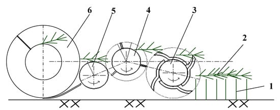
Figure 1.
Schematic diagram of the multi-stage pickup conveyor process for buckwheat: (1) Stubble; (2) buckwheat stems; (3) roll-knife knives; (4) ribbed conveying roller; (5) smooth conveying roller; (6) helical auger.
The roll-knife pickup roller (3) uses an arrangement of staggered curved blades to adapt to the pickup of buckwheat stalks in various laying states. The knife stick structure has high strength and can operate close to the ground, allowing it to adapt to different stubble heights during pickup operations. Additionally, using multiple pickup conveying rollers to pick up and convey the crop to the helical auger (6) extends the conveying distance of the buckwheat, thereby preventing stalk entanglement and reducing fluctuations in feeding caused by uneven laying of the crop, thus accommodating the significant variations in laying state due to differences in buckwheat varieties.
To minimize seed loss and ensure the smoothness and stability of the pickup process, the axis of the roll-knife pickup roller (1) is positioned relative to the ribbed conveying roller (2). The axis of the roll-knife pickup roller is rotated clockwise from the centerline of the ribbed conveying roller (2) by a certain angle, ensuring that the buckwheat stems do not experience secondary collisions or are thrown too high, which could cause seed loss. The close cooperation between the pickup conveying rollers reduces the risk of material falling off during conveyance, thereby minimizing seed loss.
2.2. Overall Structure and Working Principle of the Roll-Knife Buckwheat Pickup
The overall structure of the roll-knife buckwheat pickup is shown in Figure 2. It mainly consists of the following components: frame, spiral conveying device, roll-knife pickup roller, ribbed conveying roller, smooth conveying roller, chain drive system, and sawtooth feeding device
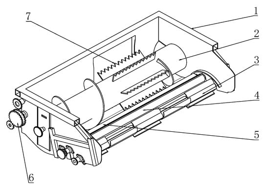
Figure 2.
Three-dimensional structure diagram of the roll-knife buckwheat pickup: (1) frame; (2) spiral conveying device; (3) roll-knife pickup roller; (4) ribbed conveying roller (5) smooth conveying roller; (6) chain drive system; (7) sawtooth feeding device.
The pickup is installed at the front of the combine harvester, which has had its cutting deck removed, forming a pickup combine harvester. During operation, the roll-knife pickup roller (3) is positioned close to the ground. The machine travels at a certain speed, and the roll-knife pickup roller (3), the ribbed conveying roller (4), and the smooth conveying roller (5) are driven by the chain drive system (6) to rotate in the same direction. The roll-knife pickup roller (3) first contacts the buckwheat stems and picks them up, lifting them. Under the effect of centrifugal force, the stems are thrown towards the ribbed conveying roller (4). Under the action of the ribbed conveying roller (4) and the smooth conveying roller (5), the material is uniformly conveyed rearward to the spiral conveying device. The spiral conveying device pushes the material to the feeding entrance, where it is fed by the sawtooth feeding device (7) into the chain rake conveying system, entering the threshing and separation system of the combined harvester to complete the entire pickup and conveying operation.
2.3. Design of the Roll-Knife Pickup Roller
2.3.1. Structure of the Roll-Knife Pickup Roller
The pickup knives are the core working components of the pickup, and their structural parameters directly affect the quality of the pickup operation. As shown in Figure 3, the roll-knife pickup roller primarily consists of a pickup roller shaft (1) and knives (2) fixed onto the shaft. The knives are installed on the pickup roller via bolts, arranged in five groups along the axis, with two knives symmetrically installed in each group around the circumference. The groups are offset from each other by 90° around the circumference to ensure uniform workload and prevent entanglement.
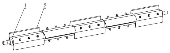
Figure 3.
Structure diagram of the roll-knife pickup roller: (1) pickup roller shaft; (2) roll-knife.
2.3.2. Kinematic Model of the Pickup Knife Roller
Let the projection point of the pickup knife roller axis O1 on the ground serve as the origin O of the coordinate system, the ground line in the direction of travel as the x-axis, and a vertical line passing through the origin as the y-axis (Figure 4).
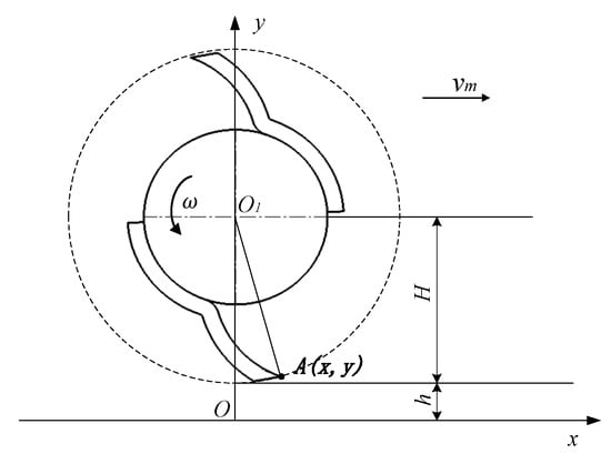
Figure 4.
Schematic diagram of the pickup knife roller’s motion.
Let the pickup knife roller start rotating counterclockwise from the position shown in the diagram. The coordinate equation for the endpoint A (x, y) of the roll-knife edge is as follows:
In Equation (1), R is the radius of rotation of the pickup knife roller (m); ω is the angular velocity of the pickup knife roller (rad/s); v is the forward speed of the harvester (m/s); t is time (s); H is installation height of the pickup knife roller (m); h is the ground clearance of the pickup (m).
From Equation (1), it is evident that the motion of the end of the pickup knife is the composition of the forward motion of the harvester and the rotational motion of the knife roller. The velocity ratio λ is defined as:
In Equation (2), va represents the linear velocity of point A at the end of the roll-knife during its rotation, and vm represents the forward speed of the harvester.
2.3.3. Simulation Analysis of the Roll-Knife Edge Motion Trajectory
The motion trajectory of the roll-knife edge was simulated and analyzed using MATLAB software (https://www.mathworks.com/support/requirements/previous-releases.html, accessed on 2 August 2024). The motion trajectories of the roll-knife end at different velocity ratios are shown in Figure 5.
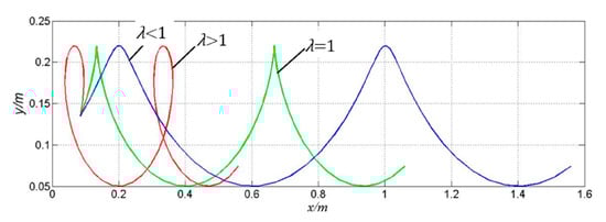
Figure 5.
Motion trajectories of the roll-knife end.
As shown in Figure 5, the motion trajectory of the roll-knife end is a cycloid, and the shape of the cycloid depends on the value of the velocity ratio λ. There are three different cases for λ: λ < 1, λ = 1, and λ > 1. In buckwheat pickup operations, it is required to promptly pick up the buckwheat stems to avoid the brushing effect between the seeds, the blade, and the root stubble, which can reduce losses caused by the pickup operation. Additionally, the pickup movement must satisfy the requirement that the roll-knife blade has a horizontal backward velocity (i.e., opposite to the direction of the harvester) when the blade moves to its highest point to achieve the purpose of throwing the buckwheat stems backward. Therefore, the linear velocity of the roll-knife end should be greater than the forward speed of the harvester, i.e., λ > 1. It is, therefore, essential to determine the interaction between the rotational speed of the knife stick and the forward speed of the harvester to optimize the pickup performance.
2.3.4. Determination of Parameters for the Pickup Knife Roller
During operation, the motion of the pickup knife roller can be divided into four parts: pickup (A1–A2), lifting (A2–A3), throwing (A3–A4), and return (A4–A1)—as shown in Figure 6.
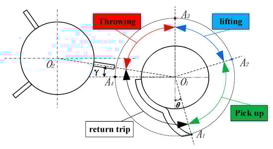
Figure 6.
Schematic diagram of the pickup process by the pickup knife stick.
- Force Analysis During Throwing
When the pickup knife roller is in the pickup position, the interaction between the roll knife and the stem is shown in Figure 4. Assume the center of mass of the buckwheat stem picked up by the spring teeth is at point B. At this point, the center of mass of the stem is subjected to the support force N from the roll-knife, friction force Ff, its own weight mg, and the centrifugal force F.
In Figure 7, α is the installation angle of the roll-knife, which is the angle between the arc curve of the roll-knife and the tangent line of the rotation circle at point B. This design specifies an installation angle of 36°. θ is the pickup angle, which is the angle between the direction of the centrifugal force and the vertical direction at the axis of the pickup roller. In the pickup area, the angle range is 15° to 105°.
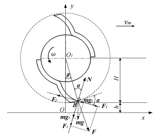
Figure 7.
Force analysis of the stem during the pickup condition.
Analysis reveals that, under the pickup condition, the condition for the buckwheat stem not to slide off the edge of the roll-knife is:
In Equation (3): φ is the friction angle of buckwheat stem, taken as 35° [29]; R is the turning radius of the knife roller, which is 85 mm in this design; m is the mass of the stem; g is the acceleration due to gravity, taken as 9.81 m/s2; ω is the rotational speed of the rolling cutter (rad/s); n is the rotational speed of the roll-knife (r/min).
From Equation (3), we find that the rotational speed n of the pickup knife roller under the pickup condition must satisfy:
By solving Equation (4), we find that the rotational speed n of the pickup to prevent the stems from being flung out must satisfy n ≤ 698.5 r/min.
- Force Analysis During Throwing
When the roll-knife is in the throwing condition, the force acting on the buckwheat stem is as shown in Figure 8.
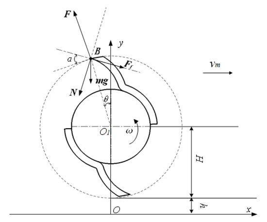
Figure 8.
Force analysis of the stem during the throwing condition.
At this point, to prevent the buckwheat stems from wrapping around the knife stick, the component of the centrifugal force F in the O1A direction must be greater than the sum of the components of the friction force Ff and the weight mg in the O1A direction. The condition for throwing the stems is thus:
From the Equation (5), we find that the rotational speed n of the pickup knife roller under the throwing condition must satisfy:
As shown in Figure 6, angle γ is the angle between the horizontal line and the line connecting the center of the roll-knife roller O1 and the center of the board tooth roller O2; in this design, γ = 10°. From this, we can determine that the range of the pickup angle θ during the throwing condition is 0° to 80°. By solving Equation (6), we find that the rotational speed n of the pickup knife stick under the throwing condition must satisfy n ≥ 382.2 r/min.
From the above analysis, we know that the knife stick rotational speed must be between 382.2 and 698.5 r/min to meet the pickup and convey the performance required for the ground roll-type pickup. We need to conduct further experimental evaluations and optimizations of the rotational speed n and the machine’s forward speed vm to determine the optimal working parameters for the pickup.
2.4. Field Performance Test
2.4.1. Test Materials
The test was conducted in October 2023 at the Shanxi Agricultural University Shenfeng Planting Test Base. The buckwheat variety selected for the test was Hongshan Buckwheat. The planting mode was wide-strip uniform sowing, with a single-row width of 200 mm, row spacing of 500 mm, and an average plant height of 1072 mm for the buckwheat.
2.4.2. Test Preparation
The harvesting was performed using a self-developed 4SW-2 type swather (Shanxi Agricultural University, Jinzhong, China), as shown in Figure 9a, with the cutting height controlled at approximately 200 mm. The buckwheat plants were laid in rows on the cuttings, as shown in Figure 9b, for the laying effect of buckwheats. At this time, the moisture content of the stems was maintained at 70%, while the moisture content of the seeds was 25%. After natural drying for seven days, the moisture content of the buckwheat plants decreased due to their natural maturation. The stem moisture content dropped to 18%, and the seed moisture content decreased to 12%, reaching the ideal moisture content for harvesting. Figure 9c shows the effect of the buckwheat after drying and entering the ideal harvest period.
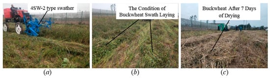
Figure 9.
Buckwheat cutting and drying operations: (a) swathing operation illustrates the operation of the 4SW-2.0 type swather during the cutting and laying process; (b) Effect of Laying shows the effect of the laid buckwheat plants after cutting; (c) Effect After Drying depicts the effect of the buckwheat after natural drying and entering the ideal harvest period.
The ground roll-type buckwheat pickup was installed on a self-developed 4LZ-1.5 type buckwheat combine harvester, which was tuned to operate effectively. Other measurement instruments included a VC6234P type tachometer (Yisheng Victor Technology Co., Ltd., Shenzhen, China), electronic scale, tape measure, marker rod, stopwatch, sieve, and tray.
2.4.3. Test Method
Following DB 14/T 2079-2020, “Technical Specifications for Buckwheat Combine Harvester Operations” [30], a continuous test field with uniform buckwheat growth was selected. The working width of the pickup header was set to two rows of planting, and a 20 m long test section was established for each pickup run, with a 2 m start-up zone at both the beginning and end of the test section. Before each test, the travel gear was adjusted to control the speed of the buckwheat combine harvester, and the rotational speed of the pickup roller was accurately measured and recorded using a VC6234P-type tachometer. During the test, a stopwatch was used to record the time it took for the machine to pass through the test section, which was then used to verify the forward speed of the machine. Figure 10 illustrates the status of the buckwheat pickup operation.
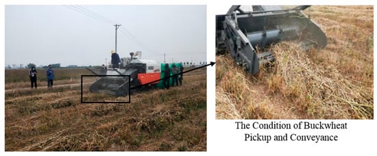
Figure 10.
The status of the buckwheat pickup operation.
After each pickup harvesting operation, three random areas measuring 1 m by 2 m were selected for data collection. Seed collection, bagging, and weighing were carried out, as shown in Figure 11, which depicts the process of collecting lost seeds.
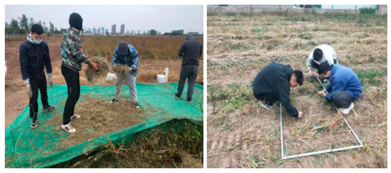
Figure 11.
The field data collection of the pickup loss rate.
2.4.4. Evaluation Criteria
The main criterion used in this study to evaluate the pickup performance of the ground roll-type pickup combine harvester is the pickup loss rate. The field performance indicator for the ground roll-type pickup header is the pickup loss rate, calculated as follows:
The average mass β of lost seeds within the sampling area is calculated using Equation (7).
In the equation: βi is the mass of lost seeds at the i-th sampling point (kg); n is the number of samplings.
The total mass ML of lost seeds over the test run is given by Equation (8):
where L is the length of a single test run in meters (m), and b is the length of a single sampling in meters (m).
The pickup loss rate U over the test run is given by Equation (9):
where MS is the total mass of harvested seeds over the test run in kilograms (kg).
2.4.5. Experimental Design
The pickup loss rate was used as the experimental index, with the forward speed of the combine harvester and the rotational speed of the pickup roller as the experimental factors. A two-factor, three-level central composite design was devised. The factor coding table is shown in Table 1. The forward speed (A) was set at 0.50 m/s, 0.75 m/s, and 1.0 m/s. The pickup roller rotational speed (B) was set at 396 r/min, 520 r/min, and 640 r/min.

Table 1.
Factor coding table.
3. Results and Discussion
3.1. Analysis of Experimental Results
The response surface optimization experimental design and testing results obtained from the above testing method are shown in Table 2. A total of 13 experimental runs were conducted, with each run repeated three times, and the statistical data were averaged.
Table 2.
Response surface optimization experimental design and results.
3.2. Establishment and Analysis of the Pickup Loss Rate Model
The experimental data from Table 2 were analyzed using Design Expert 10.0.3 software, performing variance analysis and multiple regression fitting. The forward speed (A) and the pickup roller rotational speed (B) were set as independent variables, and the pickup loss rate (Y) was set as the response value. A quadratic polynomial regression model was constructed, as shown in Equation (10). The results of the variance analysis are shown in Table 3.
Table 3.
Analysis of variance (ANOVA) for pickup loss rate.
According to Table 3, the p-value of the regression model is less than 0.001, indicating that the model has extremely high significance and excellent fit. Therefore, the model can accurately predict the response values of the regression equation. Additionally, the model’s coefficient of determination (R2) is 0.9662, and the adjusted R2 is 0.9420, meaning that 94.20% of the data can be explained by this model, further confirming its reliability. The variance analysis of the pickup loss rate shows that the first-order terms of the forward speed (A) and the pickup roller rotational speed (B) have a highly significant impact on the pickup loss rate (p < 0.01). Furthermore, by comparing the main effects of each factor, it is evident that the forward speed has a greater influence than the pickup roller rotational speed. Additionally, the interaction effect between the forward speed and the pickup roller rotational speed (AB) also has a highly significant impact on the pickup loss rate (p < 0.01).
3.3. Influence of Speed Ratio on Pickup Loss Rate
The relationship between the speed ratio and the pickup loss rate is shown in Figure 12. The speed ratio has a significant effect on the pickup loss rate, which aligns with the significant effect of the interaction (AB) between the forward speed (A) and the pickup roller rotational speed (B) found in the analysis of variance (ANOVA). The pickup loss rate initially fluctuates and then gradually increases as the speed ratio increases. When the speed ratio is less than 8, the pickup loss rate varies between 5% and 8%, which meets the pickup requirements. However, when the speed ratio exceeds 8, the pickup loss rate significantly increases. The reason for this behavior is that when the harvester maintains a constant speed, increasing the speed ratio leads to an increase in the linear speed of the rollers. As a result, the stems experience greater impact during the pickup and conveyance process, causing more grain loss.
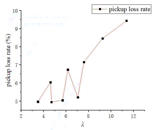
Figure 12.
Influence of Speed Ratio on Pickup Loss Rate.
3.4. Analysis of Working Parameters
The contour plot of the quadratic regression model, as shown in Figure 13, indicates that the regions with lower pickup loss rates are near the points (A = 0.5, B = 396), (A = 0.5, B = 396), and (A = 0.5, B = 396). As the forward speed (A) increases, the influence of the pickup roller rotational speed (B) on the pickup loss rate decreases. Considering the efficiency and stability of the harvester, it is recommended to select a higher forward speed and a lower roller rotational speed. The optimal working parameters for the pickup are within the range of a pickup roller rotational speed of 396–457 r/min and a forward speed of 0.9–1.0 m/s, where the pickup loss rate is smaller and better-suited to practical operational needs. Under these optimal conditions, the speed ratio ranges from 1.76 to 2.26.
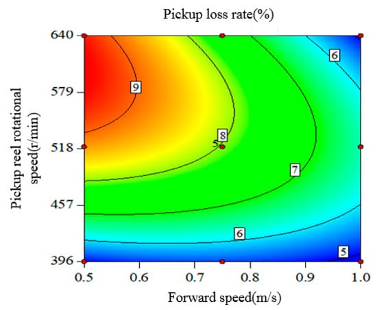
Figure 13.
Contour Plot of the Quadratic Regression Model.
3.5. Verification Test
According to the regression equation model, the predicted optimal conditions are a forward speed of 1.0 m/s and a pickup roller rotational speed of 396 r/min. Under these optimal conditions, three parallel trials were conducted, and the average pickup loss rate obtained was 5.235%, which is close to the predicted value of 4.785%. Within the tested range of conditions, the best working parameters for the picker are a forward speed of 1.0 m/s and a pickup roller rotational speed of 396 r/min.
3.6. Discussion
The roller-type picker can meet the needs of the picking operation for two-stage buckwheat harvesting, showing good adaptability to the state of laid stems and root stubble height. Notably, during field performance tests, we found that when the roller rotational speed is below a certain value (around 380 r/min), there is a high likelihood of stem entanglement around the pickup roller, causing blockages. As the pickup roller rotational speed increases, the overall pickup process becomes smoother. The reason for this is that when the pickup roller rotational speed is low, the centrifugal force is insufficient to lift the stems, leading to entanglement. This phenomenon is consistent with the force analysis conducted earlier in the study. Therefore, when using the roller-type picker for such stems, it is necessary to ensure a certain rotational speed and then determine a reasonable forward speed.
In the field trials, the designed roll-knife buckwheat pickup was configured on a self-developed 4LZ-1.5 type buckwheat combine harvester, which is specifically designed for smaller plots. Due to the limitations of the feeding capacity and the speed of the walking chassis of the combine harvester, the forward speed range for field trials was determined to be 0.5 to 1.0 m/s, while higher forward speeds were not tested. Based on the contour plot of the second-order regression model derived from the experimental data, we speculate that maintaining the speed ratio within a reasonable range may allow the roller-type picker to perform effectively at higher forward speeds, meeting the requirements for high-efficiency picking and harvesting operations. This hypothesis requires further validation through additional field trials.
In this study, only one sweet buckwheat variety grown in Jinzhong was tested. Previous studies have shown that different buckwheat varieties grown in various regions have significant differences in plant growth characteristics and planting density [31,32]. In future research, it will be necessary to further investigate the optimization of picking device parameters for different buckwheat varieties grown in different planting areas.
4. Conclusions
This paper proposes a multi-stage picking and conveying process for buckwheat seeds based on the growth characteristics of buckwheat crops. It also presents the structural design of a roll-knife buckwheat picker. Kinematic analysis was performed on the pickup roller. Through simulation and analysis of different cycloid characteristic parameters (λ), the motion trajectory of the spring fingertip was obtained. The force analysis during the picking and throwing process of the stems led to the determination of the pickup roller rotational speed range of 382.2–698.5 r/min. Field performance tests were conducted with the physical prototype of the picker mounted on a 4LZ-1.5 type buckwheat combine harvester, examining the effects of forward speed, pickup roller rotational speed, and other factors on the pickup loss rate. The results showed that the forward speed has a greater impact on the pickup loss rate compared to the pickup roller rotational speed, and the speed ratio λ has a significant effect on the pickup loss rate. When the pickup roller rotational speed is in the range of 396–457 r/min, and the forward speed is between 0.9–1.0 m/s, the pickup loss rate is minimized. Under these conditions, the optimal working parameters for the buckwheat combine harvester are a forward speed of 1.0 m/s and a pickup roller speed of 396 r/min, resulting in a pickup loss rate of 5.235% and good picking performance. Notably, when the roll-knife buckwheat pickup is used for stem picking, it is necessary to ensure a sufficiently high rotational speed to prevent stems from tangling around the roller. The appropriate forward speed should then be determined based on the speed ratio range. Future research could involve conducting field performance tests on different varieties of buckwheat in various planting areas to verify the versatility and reliability of the device. This study can provide a reference for the optimization of the picking process in two-stage buckwheat harvesting.
Author Contributions
Conceptualization, S.Y. and D.Z.; methodology, S.Y.; software, X.W.; validation, S.Y., X.W. and C.Z.; formal analysis, S.Y.; investigation, X.W.; resources, D.Z.; data curation, J.Z.; writing—original draft preparation, S.Y.; writing—review and editing, J.W.; visualization, S.Y.; supervision, D.Z.; project administration, S.Y.; funding acquisition, D.Z. All authors have read and agreed to the published version of the manuscript.
Funding
This research was funded by the Shanxi Province Basic Research Program (No. 202203021212417). Central guidance for local scientific and technological development funding projects (No. YDZJSX20231C009); Shanxi Agricultural University Academic Restoration Project (No. 2023XSHF2). Shanxi Province Basic Research Program (No. 202203021222167).
Data Availability Statement
Data are contained within the article.
Conflicts of Interest
The authors declare no conflicts of interest.
References
- Ren, C.; Shan, F.; Wang, M.; Li, Y. Review on Nutrition and Functionality and Food Product Development of Buckwheat. J. Chin. Cereals Oils Assoc. 2022, 37, 261–269. [Google Scholar] [CrossRef]
- Khan, J.; Gul, P.; Liu, K. Grains in a Modern Time: A Comprehensive Review of Compositions and Understanding Their Role in Type 2 Diabetes and Cancer. Foods 2024, 13, 2112. [Google Scholar] [CrossRef]
- Lee, L.-C.; Hou, Y.-C.; Hsieh, Y.-Y.; Chen, Y.-H.; Shen, Y.-C.; Lee, I.J.; Shih, M.-C.M.; Hou, W.-C.; Liu, H.-K. Dietary supplementation of rutin and rutin-rich buckwheat elevates endogenous glucagon-like peptide 1 levels to facilitate glycemic control in type 2 diabetic mice. J. Funct. Foods 2021, 85, 104653. [Google Scholar] [CrossRef]
- Noda, T.; Ishiguro, K.; Suzuki, T.; Morishita, T. Tartary Buckwheat Bran: A Review of Its Chemical Composition, Processing Methods and Food Uses. Plants 2023, 12, 1965. [Google Scholar] [CrossRef] [PubMed]
- Wen, W.; Li, Z.; Shao, J.; Tang, Y.; Zhao, Z.; Yang, J.; Ding, M.; Zhu, X.; Zhou, M. The Distribution and Sustainable Utilization of Buckwheat Resources under Climate Change in China. Plants 2021, 10, 2081. [Google Scholar] [CrossRef]
- Ren, C.; Cui, L.; He, F.; Ouyang, S.; Hu, X.; Li, Z.; Shan, F. Development and Construction of the Oat and Buckwheat Industry Technology System in China. J. Jilin Agric. Univ. 2018, 40, 524–532. [Google Scholar] [CrossRef]
- Liu, M. The Growth Habits and High-Yield Cultivation Techniques of Buckwheat. Hebei Agric. Mach. 2024, 8, 100–102. [Google Scholar] [CrossRef]
- Muraoka, R.; Chien, H.; Zhao, M. Production and Market Participation of Buckwheat Farmers: Micro-Evidence from Shaanxi Province, China. Sustainability 2023, 15, 4822. [Google Scholar] [CrossRef]
- Lu, Q.; Zheng, D.; Liu, Y.; Li, L.; Xu, B.; Ye, S. Problems and Considerations for the Mechanized Harvesting of Buckwheat in China. Agric. Eng. 2020, 10, 6–9. [Google Scholar]
- Cheng, T.; Wang, Q.; Ma, C.; Gan, Z.; Wan, Y.; Ye, X.; Liu, C.; Zou, X.; Zhang, J.; Guo, Y.; et al. Study on the Growth Dynamics of Tartary Buckwheat Flowers and Grains, as Well as Material Basis and Physiological Changes of Their Seed-Setting Differences. Agronomy 2024, 14, 49. [Google Scholar] [CrossRef]
- Huang, X.; Zhang, W.; Dang, W.; Zhang, K.; Feng, S.; Liu, Z.; Yang, F. Research Status and Development Trends of Buckwheat Harvesting Machinery. Agric. Mach. 2018, 10, 84–90. [Google Scholar] [CrossRef]
- Wang, X. Recent Developments and Suggestions for the Full-Mechanization Technology of Buckwheat Production in Shanxi Province. Agric. Technol. Equip. 2022, 3, 44–46. [Google Scholar]
- Hussain, S.; Zheng, D.; Song, H.; Farid, M.U.; Ghafoor, A.; Ba, X.; Wang, H.; Wang, W.; Sher, A.; Alshamali, S.J. Computational fluid dynamics simulation and optimisation of the threshing unit of buckwheat thresher for effective cleaning of the cleaning chamber. J. Agric. Eng. 2022, 53, 1230. [Google Scholar] [CrossRef]
- Huang, X.; Zhang, W.; Zhang, K.; Feng, S.; Liu, Z.; Yang, F. Experimental Study on the Cutting Flow-Horizontal Axial Flow Dual-Roller Threshing of Buckwheat. Res. Agric. Mech. 2023, 45, 183–190. [Google Scholar] [CrossRef]
- Sinkovic, L.; Pipan, B.; Neji, M.; Rakszegi, M.; Meglic, V. Influence of Hulling, Cleaning and Brushing/Polishing of (Pseudo)Cereal Grains on Compositional Characteristics. Foods 2023, 12, 2452. [Google Scholar] [CrossRef]
- Aitkin, D.J.W. Early Growth and Yield Response to Various Two-Stage Tending and Harvesting Treatments; National Library of Canada: Ottawa, ON, Canada, 2003. [Google Scholar]
- Wang, S.; Hu, Z.; Yao, L.; Peng, B.; Wang, B.; Wang, Y. Simulation and parameter optimisation of pickup device for full-feed peanut combine harvester. Comput. Electron. Agric. 2022, 192, 106602. [Google Scholar] [CrossRef]
- Wang, B.; Gu, F.; Cao, M.; Xie, H.; Wu, F.; Peng, B.; Hu, Z. Analysis and Evaluation of the Influence of Different Drum Forms of Peanut Harvester on Pod-Pickup Quality. Agriculture 2022, 12, 769. [Google Scholar] [CrossRef]
- Zhang, L.; Zhang, N.; Meng, Y.; Bao, S.; Guo, X.; Wang, C. Design and Experimental Study of a Pickup Conveyor Hay Collector. Chin. J. Agric. Mech. 2021, 42, 1–6. [Google Scholar] [CrossRef]
- Zhai, G.; Bao, S.; Li, F.; Wang, Z.; Zhang, P. Analysis of Domestic and Foreign Hay Raking Technologies and Typical Equipment. Chin. J. Agric. Mech. 2016, 37, 198–202. [Google Scholar] [CrossRef]
- Chen, Y.; Wang, G.; Wang, J.; Zhang, P.; Wang, B.; Hu, Z. Adaptabilities of different harvesters to peanut plants after cutting stalks. Int. J. Agric. Biol. Eng. 2022, 15, 93–101. [Google Scholar] [CrossRef]
- Jiang, T.; Liang, S.; Jin, M.; Tang, Q.; Wu, C. Performance Comparison Test Study of Toothed Belt and Spring-Tooth Drum Pick-up Units. Res. Agric. Mech. 2018, 40, 171–175. [Google Scholar] [CrossRef]
- Wang, Q. Design and Experimental Study of a Toothed-Belt Buckwheat Pickup Test Platform. Master’s Thesis, Northwest A&F University, Xi’an, China, 2018. [Google Scholar]
- Wang, C.; Zhang, W.; Zhang, Y.; Ding, H.; Feng, S.; Yang, F. Design and Experimental Study of a Scraper-Type Buckwheat Pickup Device. J. Southwest Univ. 2023, 45, 157–166. [Google Scholar] [CrossRef]
- Zhang, K. Study on the Overall Layout and Dynamics Simulation of Buckwheat Pickup Harvester. Master’s Thesis, Northwest A&F University, Xi’an, China, 2019. [Google Scholar]
- Lee, K.Y.; Yoo, S.; Han, B.H.; Choi, Y.; Choi, I.S. Design and Construction of a Pick-up Type Pulse Crop Harvester. J. Biosyst. Eng. 2017, 42, 12–22. [Google Scholar] [CrossRef][Green Version]
- Shu, C.; Cao, S.; Liao, Y.; Liao, Q.; Wan, X.; Li, Y. Parameter Optimization and Experiment of the Forward Lateral Spreading Device for Rapeseed Swathing Machine Based on ADAMS. Trans. Chin. Soc. Agric. Mach. 2022, 53, 11–19+38. [Google Scholar]
- Ran, J.; Hu, C.; Guo, W.; Wang, X. Design of Key Components for a New Rapeseed Windrower. Eng. Agric. 2024, 44, e20230088. [Google Scholar] [CrossRef]
- Fan, R. Study on the Kinetic Characteristics of Threshing and Cleaning for Buckwheat Harvesting Machinery. Ph.D. Thesis, Shanxi Agricultural University, Jinzhong, China, 2022. [Google Scholar]
- DB 14/T 2079-2020; Technical Specifications for Buckwheat Combine Harvester Operations. Shanxi Provincial Administration for Market Regulation: Taiyuan, China, 2020.
- Li, T. Study on the Performance of Buckwheat Production under Different Sowing Methods in Rainfed Land. Master’s Thesis, Northwest A&F University, Xi’an, China, 2017. [Google Scholar]
- Wang, J. Evaluation of Buckwheat Ecological Adaptability in the Loess Plateau Region. Master’s Thesis, Northwest A&F University, Xi’an, China, 2023. [Google Scholar]


Disclaimer/Publisher’s Note: The statements, opinions and data contained in all publications are solely those of the individual author(s) and contributor(s) and not of MDPI and/or the editor(s). MDPI and/or the editor(s) disclaim responsibility for any injury to people or property resulting from any ideas, methods, instructions or products referred to in the content. |
© 2024 by the authors. Licensee MDPI, Basel, Switzerland. This article is an open access article distributed under the terms and conditions of the Creative Commons Attribution (CC BY) license (https://creativecommons.org/licenses/by/4.0/).