Article

Design and Experimental Research on Staggered Straw Cleaning Device for No-Till Seeding in Drip Irrigation Area

1
College of Mechanical and Electrical Engineering, Xinjiang Agricultural University, Urumqi 830052, China
2
Key Laboratory of Xinjiang Intelligent Agricultural Equipment, Urumqi 830052, China
*
Author to whom correspondence should be addressed.
Agronomy 2025, 15(1), 34; https://doi.org/10.3390/agronomy15010034
Submission received: 7 November 2024 / Revised: 9 December 2024 / Accepted: 24 December 2024 / Published: 27 December 2024
(This article belongs to the Section Precision and Digital Agriculture)

Abstract

:
To solve the problem of straw cleaning and drip irrigation belt restoration for no-till seeding in drip irrigation areas, a staggered straw cleaning device was developed for no-till seeding, which is mainly composed of a front two-sided tine discs group, a drip irrigation belt laying mechanism, a middle single inner tine discs group, a rear single outer tine discs group. Different tine disc groups are set in longitudinal, transverse, and radial directions to move and throw the straw on the surface of the seeding strip. The critical parameters of the tine disc were designed and calculated, and the radius was determined to be 160 mm, the number of teeth was 12, and the theoretical working width was obtained. The movement and straw scattering process were analyzed, and the main influencing factors and the maximum straw scattering distances in the horizontal and vertical directions were determined. The interaction model of staggered tine discs group–straw–soil is established using the discrete element method (DEM). The forwarding speed, rotating speed, disc rake angle, and lateral distance of the middle tine discs were used as influencing factors, and the straw cleaning rate and the mass of straw returned in the drip irrigation coverage area were selected as the text indexes to carry out quadratic orthogonal rotation experiments. The quadratic regression model of the three sensitive parameters on the cleaning rate and the mass of straw returned in the drip irrigation coverage area was constructed and optimized. The optimal solutions were obtained: the forwarding speed was 9 km/h, the disc rake angle was 33.7°, and the lateral distance of the middle tine discs was 529 mm. The field validation test was carried out, and the results showed that the straw cleaning was 89.13%, the straw cleaning width of the seed strip was 527.2 mm, and the straw coverage rate of the drip irrigation area was 80.74%. This achievement can provide a reference for straw cleaning of no-till seeding under drip irrigation.

1. Introduction

Drip irrigation is an efficient and water-saving irrigation technology [1]. Generally, wide and narrow rows are arranged in alternate ways, and the drip irrigation belt is laid in the middle of the narrow rows [2]. No-till can contribute to sustainable agriculture [3]. Under the condition of drip irrigation, it is necessary not only to clean the straw on the seeding strip but also to lay a drip irrigation belt in the narrow rows. However, the straw has poor fluidity due to the small space in the narrow rows. If the straw is cleaned to both sides according to the conventional no-till seeding strip straw cleaning method, the straw will be in narrow rows after cleaning. During the drip irrigation laying, the drip irrigation belt and the straw will easily become entangled and form a blockage. Under the action of external force, the drip irrigation belt will break, affecting the passability and operation quality of the seeding machine. No-till seeding requires that the drip irrigation belt should be laid with minimal soil disturbance. Meanwhile, to prevent the drip irrigation belt from being blown away by the wind and reduce water evaporation, the straw should be covered on the drip irrigation belt in narrow rows after the drip irrigation is laid.
In general, the methods of cutting, removing, scattering, and diversion are used to cut and remove the surface straw of the seeding area and clear the strip without straw cover [4,5,6,7]. Cutting mainly uses a cutting disc with a cutting edge to cut off the straw or stubble [8]. Sharma et al. used a powered disc harrow to cut the straw, and the straw cleaning effect was better in areas with a small amount of straw and low toughness [9]. Kumar et al. investigated the impact of different disc coulters and operational speeds on soil disturbance and residue cutting [10]. Hegazy et al. developed a combination wheel-type stubble blocking mechanism; the cutting disc and removing wheel were installed together to drive the cutting disc to rotate and cut off the straw, and then the removing wheel removes the straw to one side of the seeding strip [11]. Huang et al. proposed the idea of driven stubble cutting and passive straw guiding, which combined straw cutting, throwing, and guiding diversion [12]. Celik et al. used a power harrow for reduced tillage and analyzed different ground-driven types of rollers and various operating conditions’ effects on the distribution of wheat residue cover on the soil surface [13]. Matin et al. proposed a strip-type crushing rotary tillage method to clean the seeding area and analyzed the influence of different blade shapes and rotational speeds on the crushing–cleaning effect combined with a high-speed camera [14]. Li et al. developed a strip-till seeder to drill seeds in zero tillage conditions with complete rice residue mulching [15].
The removal cleaning is mainly to clean the straw to the side of the seeding strip by means of throwing and sweeping [16,17]. Vaitauskien et al. designed a set of serrated disc row cleaners that are staggered longitudinally, which has a deflection angle with the forward direction of the machine. Under the rolling action of the teeth wheels, the straw on the seeding strip was pushed to both sides [18]. Chen et al. developed a vertical straw cleaning device that used the spring teeth and rake teeth to rotate actively, and the spring teeth contacted the surface straw to move the straw to one side [19]. Torbert et al. used two polyethylene hoses to push the straw and combined them with a wheel to push the straw away from the seeding strip [20]. Nelson et al. developed rotary and reciprocating rake teeth, respectively, to clean and remove straw on the seeding strip [21]. Hou et al. adopted the straw cleaning method of throwing the stubble laterally and threw the straw to the side of the seeding strip [22].
The above research provides corresponding technical support for researching straw cleaning devices. However, there is little research on straw cleaning of no-till seeding in drip irrigation areas. The drip irrigation belt and straw can easily become entangled, leading to blockages. Furthermore, it is required that the straw be evenly covered on the drip irrigation belt after the drip irrigation is laid, which increases the difficulty of no-till seeding straw cleaning. Therefore, a staggered straw cleaning device was developed for the no-till seeding of drip irrigation maize. This achievement can provide a reference for straw cleaning under drip irrigation.

2. Materials and Methods

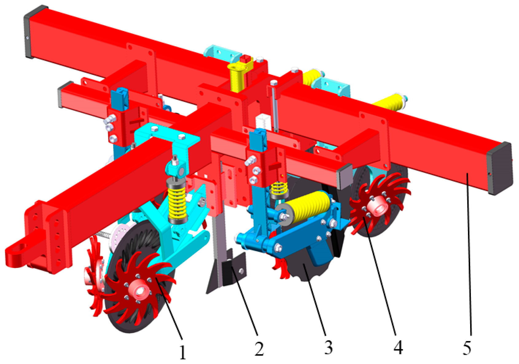
2.1. Overall Structure of Staggered Straw Cleaning Device

Based on the requirements of no-till seeding straw cleaning for drip irrigation maize, staggered tine disc groups were proposed. The staggered tine disc groups’ spatial layout is shown in Figure 1. Different tine disc groups are set in longitudinal, transverse, and radial directions to move and throw the straw on the surface of the seeding strip according to the predetermined trajectory path to meet the requirements of no-till seeding and drip irrigation belt laying. No straw is distributed on the seeding strip. After seeding and drip irrigation belt laying are completed, the straw is covered on the drip irrigation belt, and there is no straw on the seeding row.
Note: v is the forwarding speed of the machine, km/h; l1 is the lateral distance between the front tine discs group, mm; l2 is the lateral distance between the middle tine discs group, mm; l3 is the lateral distance between the rear tine discs group, mm; H1 is the height of the front tine discs group from the working surface, mm; H2 is the height of the middle tine discs group from the working surface, mm; H3 is the height of the rear tine discs group from the working surface, mm; l4 is the longitudinal distance between the front and middle tine discs group along the forward direction of the machine, mm; l5 is the longitudinal distance between the middle and rear tine discs group along the forward direction of the machine, mm.
The red dot represents the front tine discs group, the blue dot represents the middle tine discs group, and the green dot represents the rear tine discs group. The front, middle, and rear tine disc groups were all in different spatial positions. In the x-axis direction, there were the front tine discs group, the middle tine discs group, and the rear tine discs group. In the y-axis direction, the lateral distance between each tine disc group was different, and the height was different in the z-axis direction. The axis intersection points of the three groups of tine discs were O1, O2, and O3, respectively. The cleaning direction of the front tine discs group was to clean toward both outer sides along the y1-axis, the cleaning direction of the middle tine discs group was to clean toward both inner sides along the y2-axis, and the cleaning direction of the rear tine discs group was to clean toward both outer sides along the y3-axis.
According to the cleaning idea of the staggered tine discs group, the overall scheme of the staggered straw cleaning device for no-till seeding in the drip irrigation area was determined. As shown in Figure 2, the cleaning device mainly consists of a front two-sided tine discs group, a drip irrigation belt laying mechanism, a middle single inner tine discs group, a rear single outer tine discs group, a profiling mechanism, a disc cutter, and a frame. The front two-sided tine discs group was arranged in the front of the frame and was located in the middle of the narrow row, and the tine discs were symmetrically installed on both sides of the disc cutter. The drip irrigation belt laying mechanism was installed directly behind the front two-side tine discs group. The middle tine discs group was installed on the inside of the fertilization and furrowing disc, and only the two inner tine discs were set. The rear tine discs group was located on the seeding row, arranged in front of the furrow opener, and installed on the two outer sides of the disc cutter, and only the outer tine disc was provided.
The staggered tine discs group cleaning device moves under the traction of the tractor. The front two-sided tine discs group scatters the straw in the middle to both sides, the drip irrigation belt laying mechanism lays the belt in the clean middle area, the middle tine discs group throws the straw back to cover the drip irrigation belt, and the rear tine discs group scatter the straw in the strip side area to the wide row for the second time, clearing out a clean sowing strip.

2.2. Parameter Design of the Staggered Tine Discs Group Cleaning Device

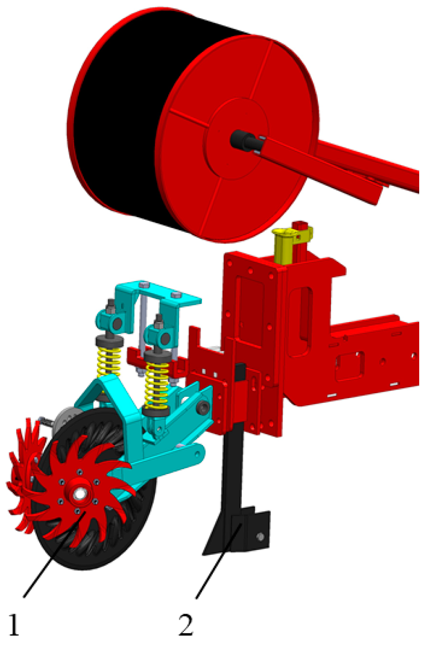
2.2.1. The Front Tine Discs Group

Figure 3 shows the front tine discs group and the drip irrigation laying mechanism, which completes the straw side throwing and drip irrigation belt laying operations in the middle area. The front tine discs group is mainly composed of two tine discs, two contoured pressure springs, a frame, a disc cutter, etc., which are located at the front of the machine and bear a large load when working. Therefore, the compression spring is used for profiling to prevent overload from affecting the life of the front tine discs group.
The drip irrigation belt laying mechanism is composed of a drip irrigation belt roll, guide cylinder, furrow opener, and reversing wheel. The material of the drip irrigation belt is a hard PE pipe with a diameter of 16 mm and a wall thickness of 0.2 mm. The width of the drip irrigation belt roll is 346 mm. The drip irrigation belt opener is required to have good performance in soil penetration and soil cutting. The angle of the furrow opener will affect the soil penetration depth and trenching resistance. If the soil penetration angle is too large, the soil disturbance will increase, and the trenching resistance will increase. On the contrary, if the soil penetration angle is too small, the working strength will be insufficient. Generally, the soil penetration angle is in the range of 15~30°. Two-sided wing plates are arranged behind the furrow opener, and the width between the wings is 75 mm. The reversing wheel is located inside the wing plates to reverse the direction of the drip irrigation belt, and prevent the drip irrigation belt from flipping over or being damaged by friction during the laying process.

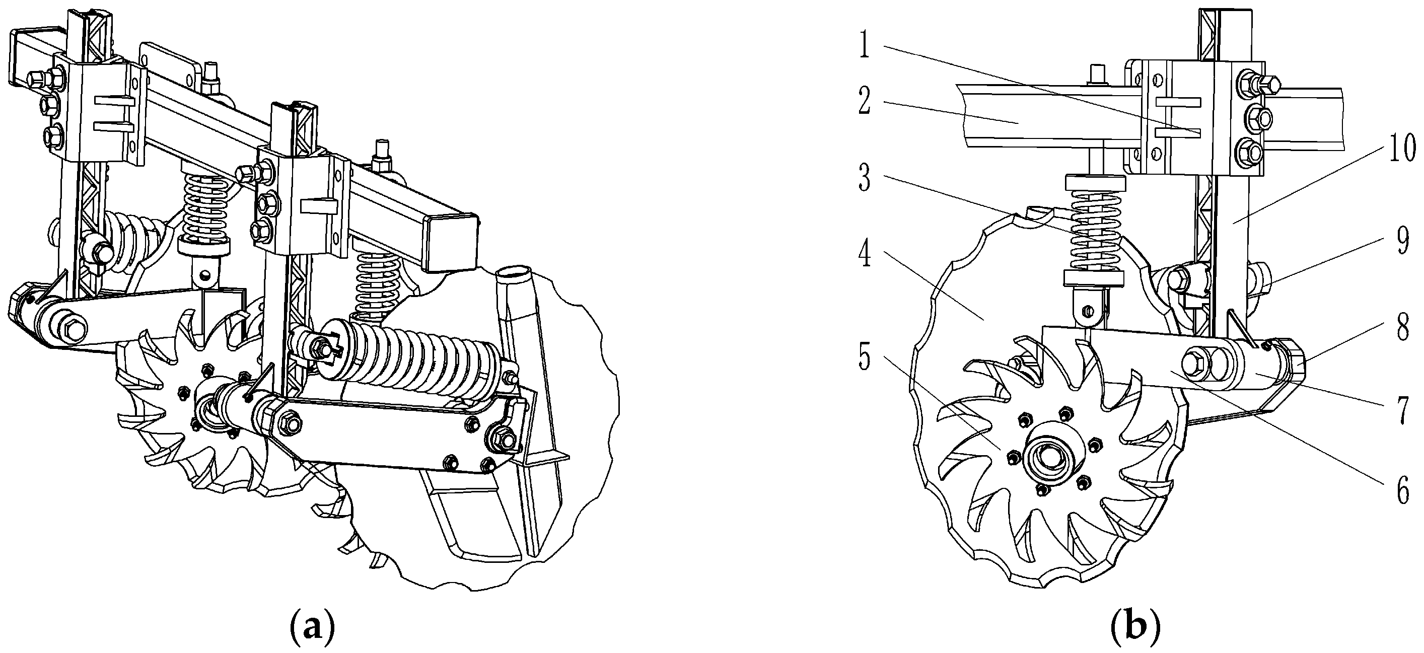
2.2.2. The Middle Tine Discs Group

The structure of the middle tine discs group is shown in Figure 4. The tine discs are arranged on both inner sides of the notched disc cutter to push the straw of the seeding strip inward to cover the drip irrigation belt. The notched disc cutter has an angle with a forward direction, which is generally 5.5° [23], so that the fertilizer furrow processed has a certain width. The fertilizer in the fertilizer box falls into the fertilizer furrow through the force feed. Both the tine disc and notched disc cutter are limited in depth and contoured by contour springs to ensure consistent soil depth and prevent impact from stones. The maximum contouring amount is determined to be 10 cm.

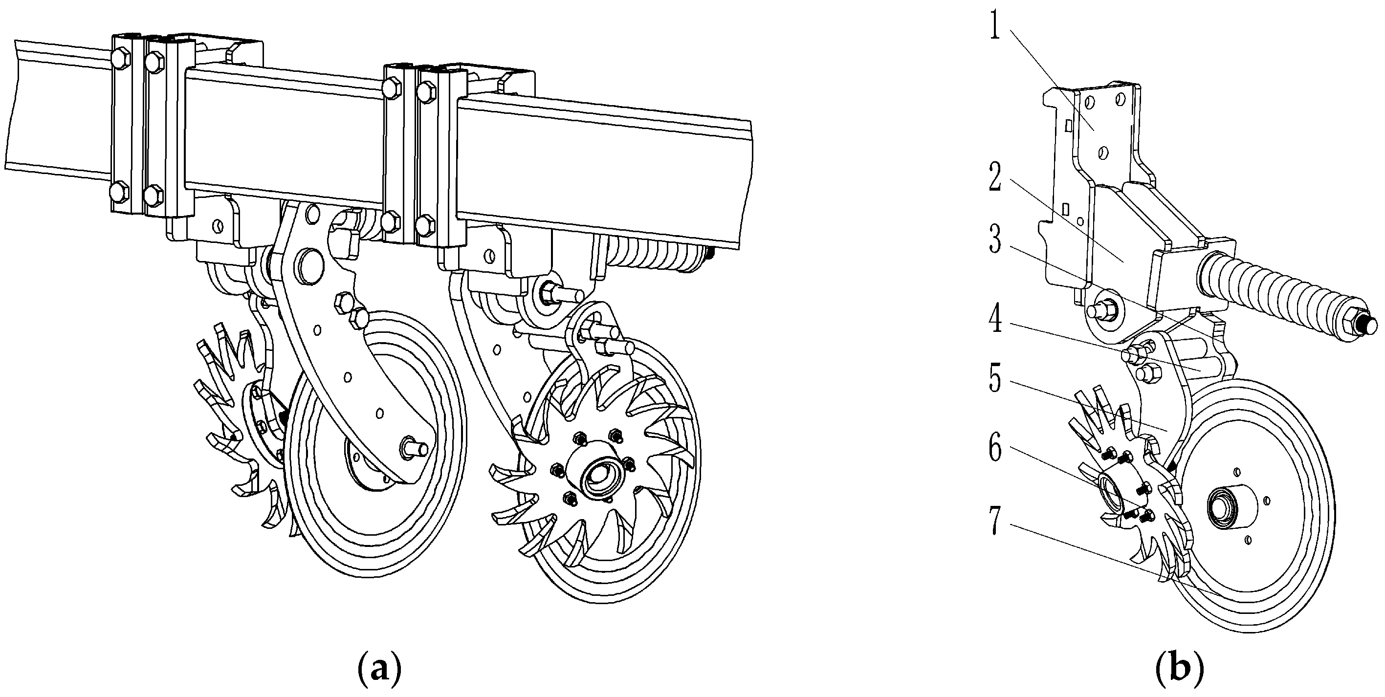
2.2.3. The Rear Tine Discs Group

The rear tine discs are arranged on the two sides of the disc cutter to clean the straw of the seeding strip to the two sides (Figure 5a). The rear tine discs group is installed on the frame of the no-till planter through a mounting base. Three groups of different mounting holes are provided on the mounting base (Figure 5b) to adjust the height of the rear tine disc group installed on the frame. The height adjustment distance is 100 mm.

2.3. Design of Tine Disc

2.3.1. The Radius of Tine Disc

The tine disc teeth are used to move the straw on the surface and throw it out. The length of the teeth should be greater than the sum of the thickness of the straw layer and the soil contacting depth of the tine disc. The average thickness of the straw layer before no-till seeding in drip irrigation areas in China is about 40 mm. In order to ensure the straw cleaning effect of the seeding strip and minimize soil disturbance, the soil contacting depth of the tine disc is generally between 20 and 40 mm.
The radius of tine disc teeth is calculated by Equation (1).
rb = Krh
where rb represents the radius of the tooth, mm; Kr represents the diameter-to-depth ratio, ranging from 1.5 to 2.5; h represents the soil contacting depth of the tine disc, mm.
The radius of the tine disc needs also meets
rb > lb + rc
where lb represents the length of teeth, mm; rc represents the maximum outer diameter of the connecting flange, mm.
When the soil contacting depth is 25 mm, the radius of the tine disc is 97.5~162.2 mm. Under the same operating parameters, the larger the radius of the tine disc, the wider the working width of the cleaning. Combined with the radius parameters of the row cleaner of no-till seeder, the radius rb of the tine disc is determined to be 160 mm. The maximum length of the teeth lb is equal to the sum of the maximum soil contacting depth of the tine disc and the thickness of the straw layer, which is 80 mm. The existing no-till seeder connecting flange is used; its maximum outside diameter rc is generally 56.5 mm. Substituting the parameters into Equation (2), it can be found that the rotation radius of the tine disc meets the parameter requirements.

2.3.2. Number of Teeth

The number of teeth n of the tine disc affects the arc length s between adjacent teeth. To ensure the continuous moving, pushing, and throwing of the straw on the surface, the arc length s should not be too large to avoid straw leakage and cleaning caused by the tine disc. If the arc length s is too small, the root of the adjacent teeth is prone to carry straw. The calculation diagram of the number of adjacent teeth is shown in Figure 6.
Calculate the number of teeth according to the agricultural design manual.
n = 2 π ( r b l c ) s
where n represents the number of teeth, pcs; lc represents the projected length of the tooth, mm; s represents the chord length of adjacent tooth roots, mm.
The diameter of maize straw is generally 15~30 mm, and the chord length s of the adjacent tooth root should be slightly larger than the straw diameter. Therefore, the chord length s of the adjacent tooth root is 38 mm, and the projected length of tooth lc is 80 mm. Substituting into Equation (3), n = 13.2 can be obtained. To maintain the balance of the tine disc during rotation, the number of teeth is an even number of 12.

2.3.3. Rotation Time

The time required for one rotation of the teeth will influence the effect of straw cleaning. In the same period, if the teeth operate more times, it indicates that their cutting and side-pushing efficiency is higher, and the straw is cleaned; the rotation process is shown in Figure 7.
The time t required for one rotation of the tine disc is
t = 0 360 n 2 π v r ( θ ) d θ 360 n
where t represents time, s; v represents forwarding speed, m/s; θ represents the polar angle of any point of the teeth edge, (°); r represents the pole diameter of any point of the teeth edge, mm; r(θ) represents the polar radius at the polar angle θ.
t = 2 π v j 0 360 n ( r 0 + K θ ) d θ 360 n
α = 360 n
K = r max r 0 α
where rmax represents the maximum polar radius, mm; r0 represents the initial polar radius, mm; α represents the teeth edge curve angle (°).
Integrate Equation (5) and substitute Equations (6) and (7) into (5) to obtain
t = ( r max + r 0 ) π v j
The time t required for a rotation of the tine disc is related to the forwarding speed v, the maximum radius rmax, and the initial polar radius r0 but is unrelated to the number of teeth n, which has no effect on the time required for one rotation. It is positively correlated with the maximum radius rmax and the initial polar radius r0, and negatively correlated with forwarding speed v; that is, the time for one rotation increases with the increase in the maximum radius rmax and the initial polar radius r0, and decreases with the increase in forwarding speed v. When the forwarding speed is 5 km/h, the time for one rotation is 0.5421 s.

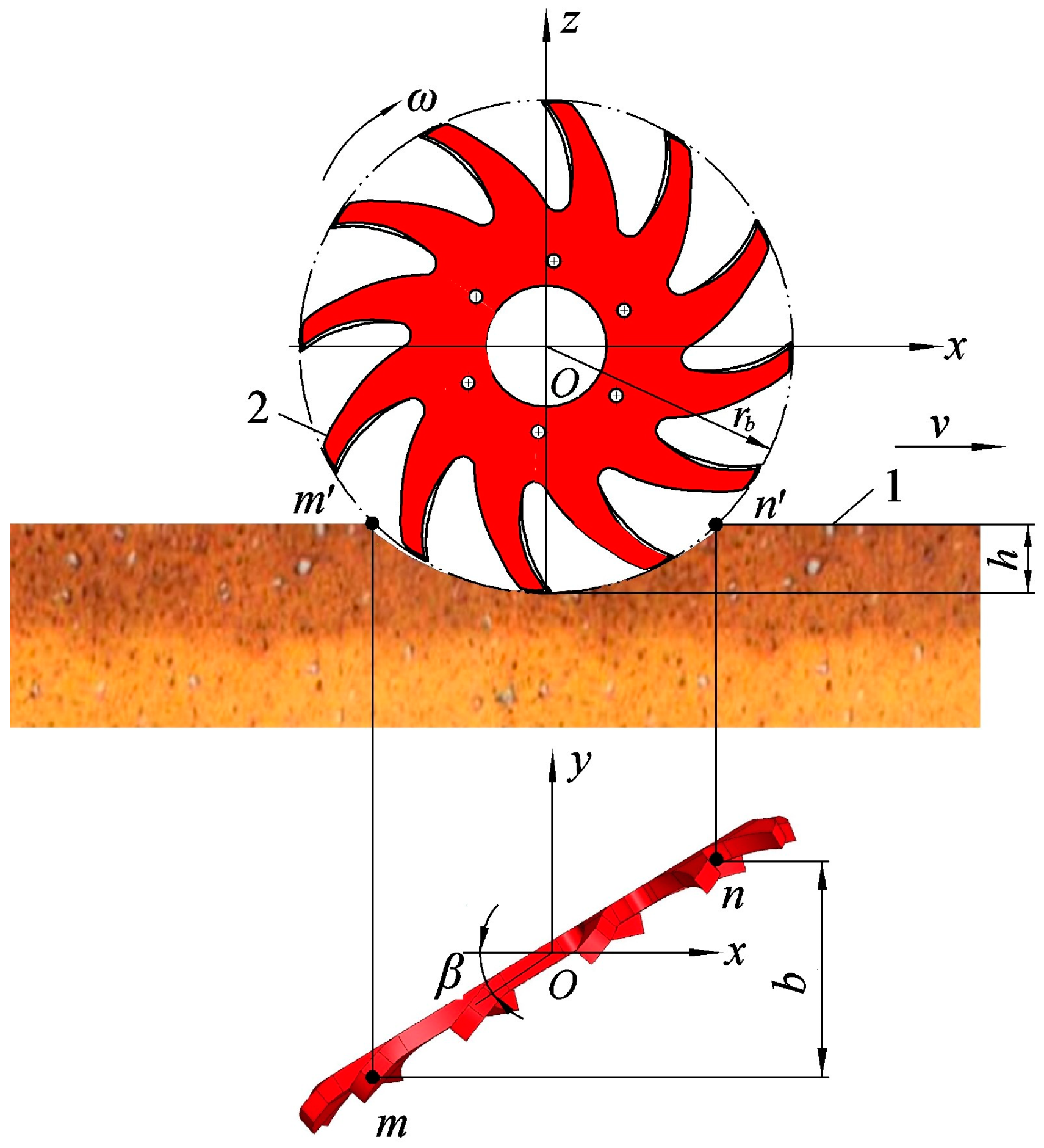
2.3.4. Theoretical Width of Tine Disc

The tine discs are distributed on both sides or one side of the stubble-cutting disc. As shown in Figure 8, the x-axis is the longitudinal forward direction, the y-axis is the lateral offset direction, the z-axis is the vertical height direction on the ground, and v is the forwarding speed. The intersection points of the teeth and the horizontal line of the soil surface are m and n, respectively, and the effective working width of the tine disc on the xoy plane is b.
The distance between the teeth and the soil surface is
l m n = r b 2 ( r b h ) 2
where lmn represents the distance between the teeth and the soil surface, mm.
The theoretical width of the tine disc is
b = l m n sin β = sin β r b 2 ( r b h ) 2
where b represents the theoretical width of the tine disc, mm; β represents the disc rake angle, which is the angle between the circumferential plane of the tine disc and the direction of disc traveling (°).
From Equation (10), it can be seen that the theoretical width of the tine disc is related to the radius, disc angle, and the soil contacting depth of the tine disc. The disc angle is generally 20~40° [24]. The soil contacting depth of the tine disc affects the positions of the intersection points m and n, the torque of the tine disc rotation, and the amount of soil disturbance. If the depth is too small, the width of the tine disc will be small, and the friction and rotational torque will be small. When the depth is too large, the resistance of the tine disc to contact with the soil is large, and the amount of soil disturbance is increased.

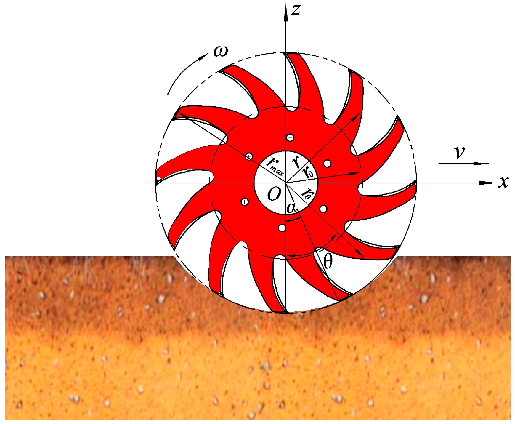
2.3.5. Kinematic Analysis of Tine Disc

The tine disc moves along the forward direction of the seeder under the traction of the tractor, and the teeth of the tine disc contact the straw on the surface and soil to generate friction. Under the coupling action of tractor pulling force and soil reaction, the teeth of the tine disc rotate passively around the fixed axis, and the rotation direction is consistent with the forward direction of the seeder. The rotating teeth of the tine disc pick up the straw on the surface and throw it to the side and rear.
The movement of the tine disc is simultaneously self-rotation and forward, so the absolute motion of any point on the tooth is the synthesis of the rotational and the forward motion, and its motion trajectory is a cycloid, as shown in the blue curve in Figure 9.
A plane coordinate system is established with the tooth rotation center as the origin. The positive direction of the x-axis is consistent with the forward direction of the seeder, and the z-axis is vertically upward. The motion of any endpoint A on the tooth is analyzed. In the beginning, the endpoint of the tooth is located at the horizontal position A0 in front of the tooth, which positively coincides with the x-axis. The component velocity of the endpoint A of the tooth in the x-axis and z-axis directions is
v x = d x d t = v r ω sin ω t v z = d z d t = r ω cos ω t
where θ represents the tooth rotation angle, rad; ω represents the angular velocity, rad/s.
Then, the absolute velocity vA of the tooth endpoint A is
v A = v 2 2 v r ω sin ω t + ( r ω ) 2
According to Figure 9 and the structure of the tine disc, it can be seen that
sin ω t = r h r = 1 h r
From Equations (12) and (13), the main structural parameters that affect the absolute velocity of the end of the tine disc teeth are the forwarding speed v, the soil contacting depth of tine disc h, the radius r, and the angular velocity ω. According to the structural parameters of the commonly used disc teeth and the agronomic requirements of no-till seeding [24], the tine disc rotation radius is determined to be 320 mm, the disc angle is 30°, and the rotation speed of the tine disc is proportional to the forwarding speed of the seeder.
The straw cover on the ground is cut off and broken by the tine disc and thrown to the side and rear. The instantaneous motion of the teeth throwing the straw is analyzed. The straw is simplified as a particle, the tine disc moves at a uniform speed, and the influence of air resistance and the collision between straws are ignored. The straw-throwing process by the teeth of the tine disc is shown in Figure 9.
Point a is the critical point where the maize straws are separated from the teeth of the tine disc. When the teeth of the tine disc move from point a to point d, the maize straw slides outward along the teeth, and the teeth of the tine disc push the straw to the side and rear. Point a is the starting point of the maize straw being thrown, then the instantaneous velocity va of the maize straw being thrown at point a is the component velocity vax in the x-axis direction and the component velocity vaz in the z-axis direction.
v a x = v a cos β = ω ( r h 1 ) v a z = v a sin β = ω 2 r h 1 - h 1 2
where va represents the instantaneous speed at which maize straw is thrown out of the teeth of the tine disc, m/s; β represents the angle between the instantaneous direction of maize straw being thrown and the horizontal direction, (°); h1 represents the vertical distance between the starting point of maize straw throwing and the bottom of the seed furrow, mm.
The straw is thrown out of the teeth of the tine disc and then performs parabolic motion. The motion trajectory equation is:
x a = 2 r h 1 h 1 2 ( r h 1 ) ω t sin α y a = r ω t cos α z a = h 1 r + 2 r h 1 h 1 2 ω t g t 2 2
where xa represents the distance of maize straw thrown in the x-axis direction, mm; ya represents the distance of maize straw thrown in the y-axis direction, mm; za represents the distance of maize straw thrown in the z-axis direction, mm.
According to Equation (15), the maximum distance l that the teeth of the tine disc throw the straw horizontally backward is
l = 2 ω 2 ( r h 1 ) 2 r h 1 h 1 2 g cos α
where g represents gravity acceleration, m/s2.
The maximum lateral throwing distance of straw in the horizontal plane perpendicular to the forward direction is
L 3 2 = l tan α   = 2 ω 2 ( r h 1 ) 2 r h 1 h 1 2 g sin a
Similarly, the maximum vertical throwing height of straw h2 is
h 2 = v a sin β 2 2 g = ω 2 r h 1 h 1 2 2 g
As the teeth of the tine disc move from point a to point d, the straw is constantly thrown. During this process, the straw throwing instantaneous speed va is the same, but the direction is different. When the teeth of the tine disc move to point d, vax = 0, the straw is no longer thrown outward. From Equations (16)–(18), it can be seen that the distance of straw throwing in the horizontal backward, lateral, and vertical directions changes with the change of the va direction. When the angle β = 45°, the throwing distance is the largest. If the forwarding speed is 6~10 km/h, the disc angle is 30°, substituting into Equations (16)–(18), the maximum horizontal throwing distance of the straw is 246.4–682.7 mm, the maximum lateral throwing distance is 142.2–393.9 mm, and the maximum vertical throwing height of straw is 71.1–197.1 mm.

2.4. DEM Simulation

2.4.1. The Interaction Model of Staggered Tine Discs Group–Straw–Soil

A soil–straw simulation model was established by using EDEM 2020 discrete element software. Considering the computational power and simulation efficiency comprehensively, spherical particles with a radius of 5 mm were selected as soil particles. The Hertz–Mindlin with no slip contact model was used as the mechanical relationship model between soil particles. The soil density is 1850 kg/m3, Poisson’s ratio is 0.38, and the shear modulus is 1.0 × 10⁶ Pa [25]. The straw diameter measured in the field was in the range of [15, 30] mm, so the straw diameter was selected as 18 mm. In the simulation process, the cutting impact of the straw was not considered, and the cleaning and moving effect of the tine discs on the straw was mainly observed, so the length of the straw was selected as the length after cutting. A linear model with a length of 118 mm and an interval of 5 mm between spherical centers was adopted as the straw particle model. The straw density is 180 kg/m3, Poisson’s ratio is 0.3, and the shear modulus is 1.0 × 10⁶ Pa [26].
Combined with the no-till seeding working width of drip irrigation and the straw coverage in the field before seeding, the primary size of the soil bin (length × width × height) was set to 2500 mm × 1400 mm × 140 mm, the soil layer thickness was 140 mm, and the straw layer thickness was 40 mm. Soil particles were randomly generated and fell, soil and straw settling naturally under gravity so that the simulation is consistent with the actual as much as possible. The established interaction model of staggered tine discs group–straw–soil is shown in Figure 10.
During the simulation operation, the tine disc–soil, tine disc–straw, soil particle–soil particle, and soil particle–straw will all come into contact and produce relative movement. The primary contact parameters of discrete element simulation were set according to relevant research [27,28], as shown in Table 1.
A staggered tine discs group straw cleaning device was set at one end of the soil-straw model for initial operation. The total simulation time was set to 2.2 s, the fixed time step was 2.8 × 10⁻⁵ s, and the mesh size was set to 2.5 times the minimum soil particle size.
The straw cleaning rate is calculated by recording and counting the change of straw mass in the seeding area.
c = m m 1 m × 100 %
where c is straw cleaning rate, %; m is initial straw mass in the seeding strip before operation, kg; m1 is straw mass in the seeding strip after operation, kg.
Similarly, the straw mass located in the drip irrigation area after operation is measured.

2.4.2. Test Design and Index Measurement

According to the above theoretical analysis, the forwarding speed of the machine and the disc rake angle were the main influencing factors. At the same time, the lateral distance of the middle tine disc group also influences the straw movement. A quadratic orthogonal rotation test was conducted to analyze the interactive effects of the three factors on the straw movement of the seeding strip and obtain the optimal parameter combination for straw cleaning. The straw cleaning rate and the mass of straw returned in the drip irrigation coverage area were selected as the text indexes, and the Box–Behnken experimental scheme was selected. The factors and levels are shown in Table 2.

2.5. Field Experiment

A field experiment was conducted in Bole, Xinjiang Uygur Autonomous Region, China. The average coverage of maize straw in the field was 1.69 kg/m2. The soil compaction and 0~100 mm soil water content was 1348 kPa and 23.9%, respectively. The main instruments and equipment are a 904 tractor (Zoomlion Heavy Industry Science&Technology Co., Ltd., Changsha, China), electronic balance (Shenzhen Mobil Electronics Co., Ltd., Shenzhen, China), SC-900 soil compaction meter (Spectrum Technologies, Inc., Aurora, IL, USA), ruler, sealed bag, marker, experimental label, etc.
According to the performance test requirements of NY/T 1768-2009 “Technical Specifications for Quality Evaluation of No-till seeder”, the straw cleaning rate of the seeding strip, straw cleaning width, and straw coverage rate of drip irrigation area were selected as test indexes to comprehensively evaluate the straw cleaning performance of a no-till seeder for drip irrigation. The length of each measuring area is 80 m, including 10 m preparation and adjustment areas at both ends, and the 60 m in the middle for stable working is the test area. Observe and record the number of times it is blocked and shut down to deal with blockages during operation. No blockage or only one minor blockage is qualified.

3. Results and Discussion

3.1. Data Analysis of EDEM Simulation Test

3.1.1. Establishment of Regression Model and Significance Analysis
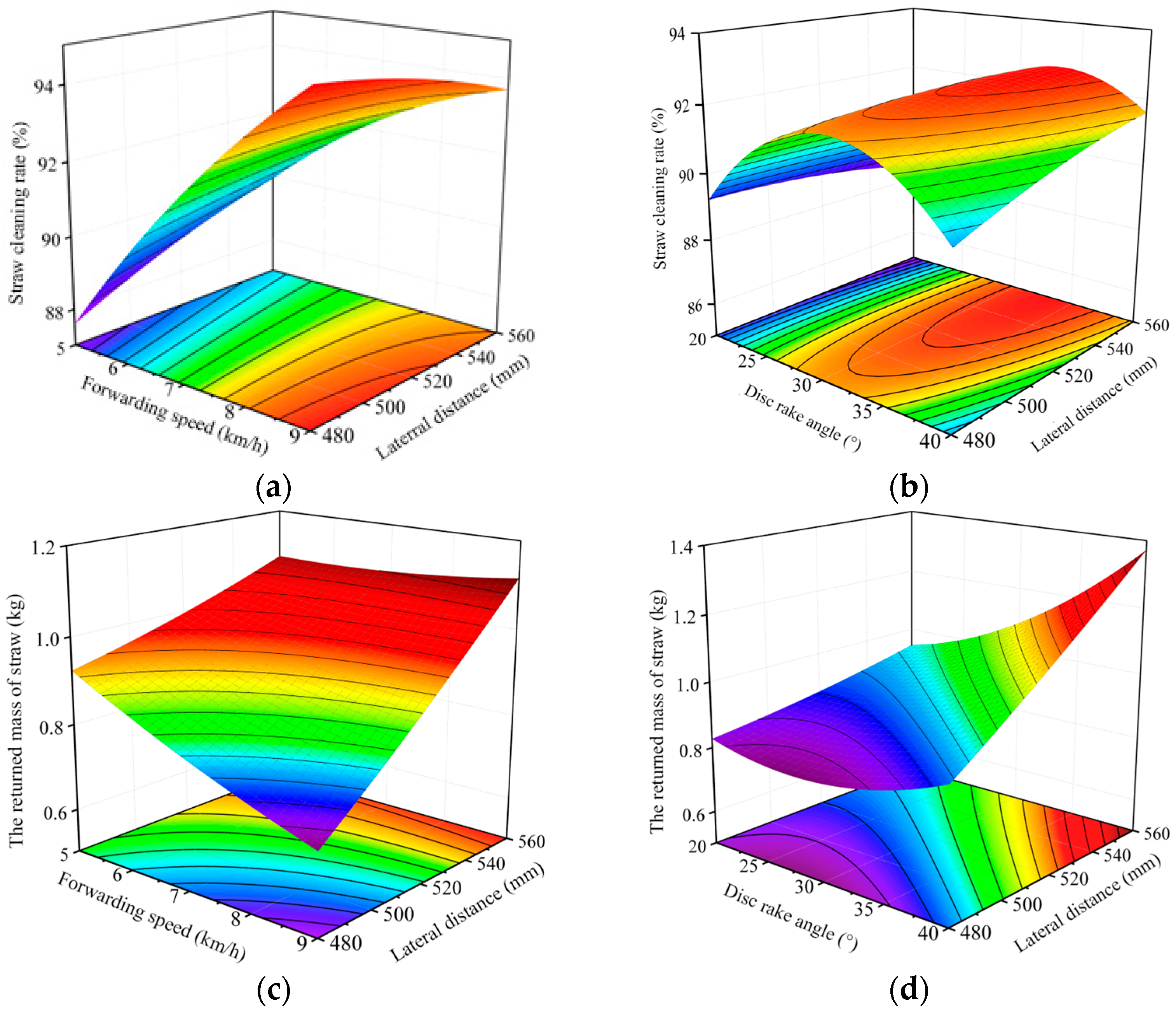
The simulation tests were carried out according to the experimental scheme, and the test index values of each group of tests were calculated after the test was completed. The test scheme and results are shown in Table 3. A multivariate regression fitting analysis was performed on the simulation results to obtain the regression fitting equations of the straw cleaning rate y1 in the seeding strip and the mass of straw returned in the drip irrigation coverage area y2, and the significance was tested.
  • Straw cleaning rate
Regression fitting was performed on the experimental data, and the significance test was conducted on the straw cleaning rate y1, as shown in Table 4. The model fit was highly significant (p < 0.01). The primary term x1, x2, the quadratic term x22, and the interaction term x1x3, x2x3 had highly significant on the straw cleaning rate, the primary term x3 was significant, and the quadratic term x12 was more significant, while the quadratic term x32 and the interaction term x1x2 were all no significant effect (p > 0.05). The results showed that there was a quadratic relationship between the three selected experimental factors and the straw cleaning rate. The order of the influence of each experimental factor on the experimental index y1 was the forwarding speed, the disc rake angle, and the lateral distance of the middle tine discs group. The insignificant were removed, and the regression mathematical model of straw cleaning rate y1 was established (Equation (20)).
y 1 = 92.31 + 2.81 x 1 + 0.93 x 2 + 0.25 x 3 0.92 x 1 x 3 + 0.63 x 2 x 3 0.52 x 1 2 2.34 x 2 2
2.
The mass of straw returned in the drip irrigation coverage area
The significance test of the mass of straw returned in the drip irrigation coverage area y2 is shown in Table 4. The regression model of the mass of straw returned in the drip irrigation coverage area y2 was highly significant. The primary term x2, x3, and the interaction term x2x3 were highly significant, and the primary term x1, the interaction term x1x3, and the quadratic term x22 were more significant, while the quadratic terms x12, x32 and the interaction term x1x2 were all not significant. The order of the influence of each experimental factor on the experimental index y2 was the lateral distance of the middle tine discs group, the disc rake angle, and the forwarding speed. The insignificant were removed, and the regression mathematical model of the mass of straw returned in the drip irrigation coverage area y2 was established (Equation (21)).
y 2 = 0.93 0.053 x 1 + 0.12 x 2 + 0.15 x 3 + 0.067 x 1 x 3 + 0.090 x 2 x 3 + 0.070 x 2 2

3.1.2. Analysis of the Influence of the Indexes on the Straw Cleaning and the Mass of Straw Returned in the Drip Irrigation Coverage Area

When the disc rake angle was 30°, the straw cleaning rate increased with the increase in the forwarding speed (Figure 11a). When the forwarding speed was 5 km/h, and the lateral distance increased from 480 mm to 560 mm, the change trend of straw cleaning rate was not obvious. However, when the forwarding speed was 9 km/h and the lateral distance increased from 480 mm to 560 mm, the straw cleaning rate showed a decreasing trend. The straw cleaning rate increased first and then decreased with the increase in the disc rake angle and increased with the increase in the lateral distance (Figure 11b). The mass of straw returned in the drip irrigation coverage area increased with the increase in the lateral distance and decreased with the increase in the forwarding speed (Figure 11c). The mass of straw returned in the drip irrigation coverage area increased with the increase in the disc rake angle and the lateral distance (Figure 11d).

3.1.3. Parameter Optimization and Verification of Desirability

Combined with the results of response surface analysis, the regression models of the two experimental indexes were optimized and solved. The objective function and boundary constraints were as follows:
max   y 1 ( x 1 , x 2 , x 3 ) 1.0   kg y 2 1.2   kg   s . t 5   k m / h x 1 9   km / h 20 ° x 2 40 ° 480   mm x 3 560   mm
Multiple groups of optimal parameter combinations were obtained by solving the objective function. According to the actual straw cleaning requirements of no-till seeding operation, the optimal parameter range was selected. When the forwarding speed was 9 km/h, the disc rake angle of the middle tine discs was 33.7°, the lateral distance of the middle tine discs groups was 529 mm, the maximum straw cleaning rate was 94.6%, the return mass of the drip irrigation coverage area was 1.0 kg.
The above optimal parameters were verified by simulation experiment; the straw cleaning rate and the mass of straw returned in the drip irrigation coverage area were 94.11 mm and 1.06 kg, respectively. The straw cleaning rate and the mass of straw returned obtained by the simulation verification experiment have certain differences from the optimized results, but the difference is slight, within 0.6 percentage points, which meets the requirements of drip irrigation maize no-till seeding operations.

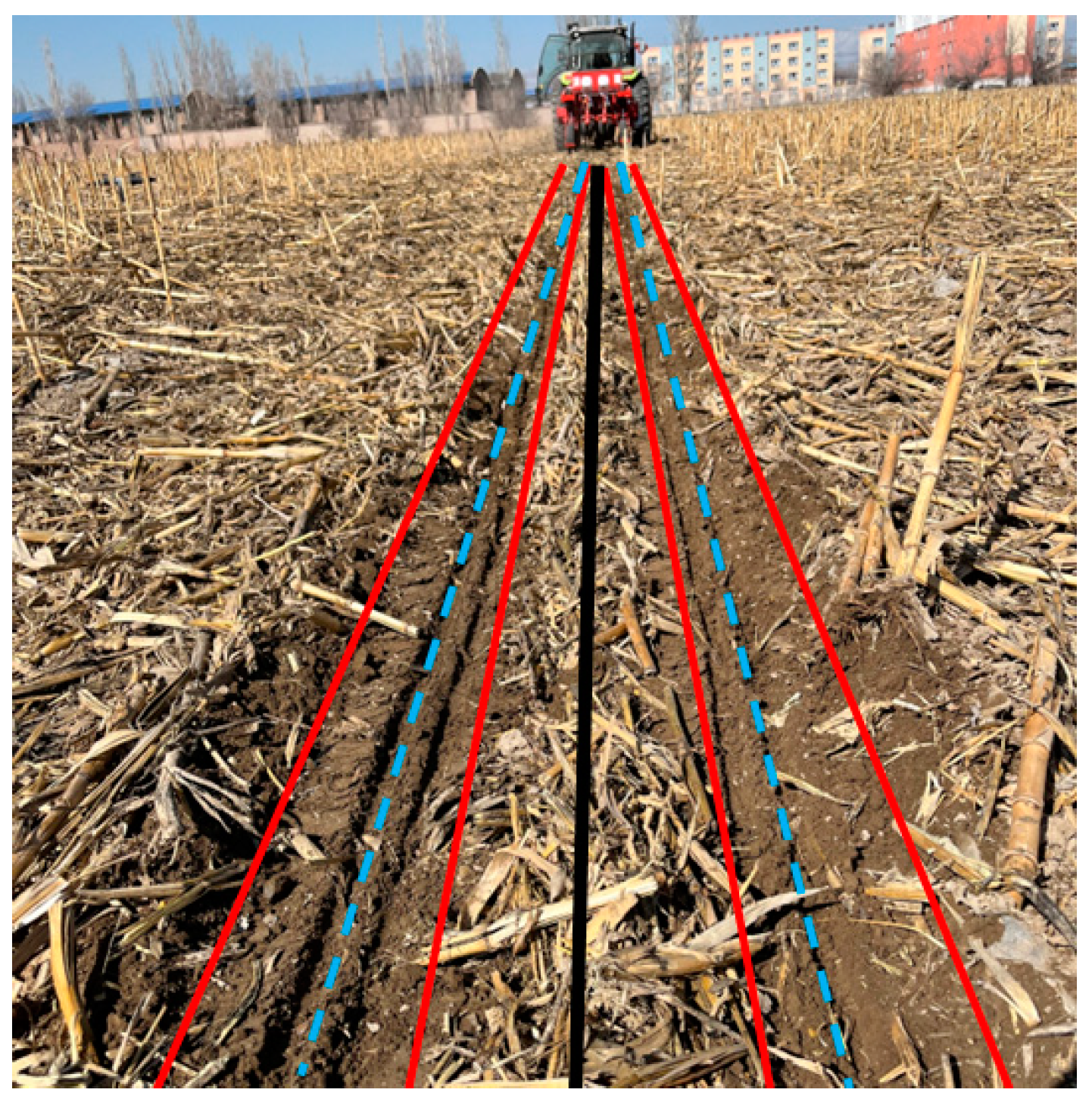
3.2. Field Experimental Results

According to the simulation optimization results, the forwarding speed was set to 9 km/h, the disc rake angle was 33.7°, and the lateral distance of the middle tine discs was 529 mm. The field validation experiments were conducted. The effect of no-till seeding straw cleaning and belt covering of drip irrigation after the operation is shown in Figure 12. The field experiment results are shown in Table 5.

3.3. Discussion

Base fertilizer is generally applied below the seed side, 40~80 mm from one side of the seed row. There are two main ways to apply fertilizer: fertilizer is applied on the inside or outside of the seed row. The middle tine discs group is installed together with the fertilizer disc, and the change in lateral distance will affect the straw throwing position and flow. When fertilizer is applied on the outside of the seed row, the fertilizer disc is installed on the outside relative to the seed row, and the lateral spacing between the fertilizer discs is adjustable in a range of 480~560 mm, with an increment of 40 mm. On the contrary, when fertilizer is applied on the inside of the seed row, the fertilizer disc is installed on the inside relative to the seed row, and the maximum setting range of the lateral distance between the fertilization disc is 240~320 mm. In preliminary experiments, the lateral distance of 240~320 mm on the inner side failed to effectively return the straw, making it impossible to cover the drip irrigation belt with straw.
In previous studies on straw cleaning for no-till seeding in drip irrigation areas [2], the straw in narrow rows was moved to adjacent wide rows to provide a suitable working environment for laying a drip irrigation belt, but the straw return to cover the drip irrigation belt after laying was not achieved. The staggered straw cleaning device proposed in this study not only achieves straw cleaning, but also can cover the drip irrigation belt with straw. In the field experiment, the straw cleaning rate increased from 87.61% to 89.13%, and the seeding strip cleaning widths were 523.3 mm and 527.2 mm, with little difference.

4. Conclusions

(1)
A method and overall plan for cleaning surface straw for drip irrigation and no-tillage corn sowing were proposed, which adopted staggered tine discs group cleaning technology. The front tine discs group, drip irrigation belt laying mechanism, and middle and rear tine discs group were designed, and the basic structures and parameters were determined. The motion trajectory of the working end point of the tine disc teeth and the process of straw throwing were analyzed, and the motion trajectory equation of the maize straw in a parabola after it was thrown out of the disc teeth was obtained. The maximum distance of straw thrown backward horizontally ranges from 246.4 mm to 682.7 mm, the maximum distance of straw thrown sideways horizontally ranges from 142.2 to 393.9 mm, and the maximum height of straw thrown in the vertical direction ranges from 71.1 to 197.1 mm.
(2)
The optimal solutions of the cleaning rate and the mass of straw returned in the drip irrigation coverage area were obtained. The forwarding speed was 9 km/h, the disc rake angle was 33.7°, and the lateral distance of the middle tine discs was 529 mm.
(3)
The field test verification results showed that the straw cleaning was 89.13%, the straw cleaning width of the seed strip was 527.2 mm, and the straw coverage rate of the drip irrigation area was 80.74%.

Author Contributions

Conceptualization, P.Y. and X.Z. (Xingliang Zhu); writing—original draft preparation, P.Y.; writing—review and editing, X.Z. (Xuejun Zhang), J.Y. (Jia You), J.Y. (Jinshan Yan) and S.Q. All authors have read and agreed to the published version of the manuscript.

Funding

This research was funded by the National Natural Science Foundation of China (52165039, 32460450), “Tianshan Talents-three rural Areas” Key Talent Training Project in Xinjiang Uygur Autonomous Region (2022SNGGGCC020), Xinjiang Uygur Autonomous Region Major Science and Technology Special Projects and Key R&D Plan (2022A02003-3, 2022B02025-3).

Data Availability Statement

The data presented in this study are available on request from the corresponding author.

Conflicts of Interest

The authors declare no conflicts of interest.

References

  1. Si, J.; Wang, L.; Zhang, K.; Li, L.; Fudjoe, S.K.; Luo, Z. Irrigation as an Effective Way to Increase Potato Yields in Northern China: A Meta-Analysis. Agronomy 2024, 14, 448. [Google Scholar] [CrossRef]
  2. Yuan, P.; Li, H.; Jiang, G.; He, J.; Lu, C.; Huang, S. Design and Experiment of Straw Cleaning Device for Wide-narrow Maize No-tillage Sowing Strip in a Drip Irrigation Area. Trans. Chin. Soc. Agric. Mach. 2021, 52, 43–52. [Google Scholar]
  3. Phefadu, K.C.; Munjonji, L. Assessing the Impact of No-Tillage Duration on Soil Aggregate Size Distribution, Stability and Aggregate Associated Organic Carbon. Agronomy 2024, 14, 2482. [Google Scholar] [CrossRef]
  4. He, J.; Li, H.; Chen, H.; Lu, C.; Wang, Q. Research progress of conservation tillage technology and machine. Trans. Chin. Soc. Agric. Mach. 2018, 49, 1–19. [Google Scholar]
  5. Yuan, P.; Li, H.; Lu, C.; Wang, Q.; He, J.; Huang, S.; Cui, D. Design and experiment of seed furrow cleaning device based on throwing and sliding for no-till maize seeding. Int. J. Agric. Biol. Eng. 2022, 15, 95–102. [Google Scholar] [CrossRef]
  6. Arvidsson, J.; Hillerström, O. Specific draught, soil fragmentation and straw incorporation for different tine and share types. Soil Tillage Res. 2010, 110, 154–160. [Google Scholar] [CrossRef]
  7. Zeng, Z.; Chen, Y. Simulation of straw movement by discrete element modelling of straw-sweep-soil interaction. Biosyst. Eng. 2019, 180, 25–35. [Google Scholar] [CrossRef]
  8. Wang, Q.; Cao, X.; Wang, C.; Li, H.; He, J.; Lu, C. Research Progress of No/Minimum Tillage Corn Seeding Technology and Machine in Northeast Black Land of China. Trans. Chin. Soc. Agric. Mach. 2021, 52, 1–15. [Google Scholar]
  9. Sharma, V.K. Development and Performance Evaluation of a Multi-Toolbar No-Till Seed Drill for Surface Managed Loose Straw Conditions After Combining. Ph.D. Thesis, GB Pant University of Agriculture and Technology, Pantnagar, India, 2014. [Google Scholar]
  10. Kumar, N.; Sawant, C.; Sharma, R.; Chhokar, R.; Tiwari, P.; Singh, D.; Roul, A.; Tripathi, S.; Gill, S.; Singh, G. Combined effect of disc coulters and operational speeds on soil disturbance and crop residue cutting under no-tillage system in soil bin. J. Sci. Ind. Res. 2021, 80, 739–749. [Google Scholar] [CrossRef]
  11. Hegazy, R.; Dhaliwal, I. Evaluation of a Power Driven Residue Manager for No-till Drills. Asian J. Agric. Res. 2011, 5, 127–136. [Google Scholar] [CrossRef]
  12. Huang, Y.; Gao, P.; Zhang, Q.; Shen, H.; Zhu, R.; Shen, J. Design and experiment of grass soil separation device with combination of stubble cutting and grass guiding used for no-till planter. Trans. Chin. Soc. Agric. Mach. 2020, 51, 67–78. [Google Scholar]
  13. Celik, A.; Altikat, S. The effect of power harrow on the wheat residue cover and residue incorporation into the tilled soil layer. Soil Tillage Res. 2022, 215, 105202. [Google Scholar] [CrossRef]
  14. Matin, M.A.; Fielke, J.M.; Desbiolles, J.M.A. Torque and energy characteristics for strip-tillage cultivation when cutting furrows using three designs of rotary blade. Biosyst. Eng. 2015, 129, 329–340. [Google Scholar] [CrossRef]
  15. Li, C.; Tang, Y.; McHugh, A.D.; Wu, X.; Liu, M.; Li, M.; Xiong, T.; Ling, D.; Tang, Q.; Liao, M.; et al. Development and performance evaluation of a wet-resistant strip-till seeder for sowing wheat following rice. Biosyst. Eng. 2022, 220, 146–158. [Google Scholar] [CrossRef]
  16. Matin, M.A.; Desbiolles, J.M.A.; Fielke, J.M. Strip-tillage using rotating straight blades: Effect of cutting edge geometry on furrow parameters. Soil Tillage Res. 2016, 155, 271–279. [Google Scholar] [CrossRef]
  17. Cao, X.; Wang, Q.; Li, H.; He, J.; Lu, C. Combined row cleaners research with side cutter and stubble clean disk of corn no-till seeder. Trans. Chin. Soc. Agric. Mach. 2021, 52, 36–44. [Google Scholar]
  18. Vaitauskienė, K.; Šarauskis, E.; Romaneckas, K.; Jasinskas, A. Design, development and field evaluation of row-cleaners for strip tillage in conservation farming. Soil Tillage Res. 2017, 174, 139–146. [Google Scholar] [CrossRef]
  19. Chen, G.; Wang, Q.; Li, H.; He, J.; Wang, X.; Zhang, X.; He, D. Experimental research on vertical straw cleaning and soil tillage device based on Soil-Straw composite model. Comput. Electron. Agric. 2024, 216, 108510. [Google Scholar] [CrossRef]
  20. Torbert, H.A.; Ingram, J.T.; Prior, S.A. Planter aid for heavy residue conservation tillage systems. Agron. J. 2007, 99, 478–480. [Google Scholar] [CrossRef]
  21. Nelson, W.S.; Shinners, K.J. Performance of rake mechanisms for cheating residue free seed bands. Am. Soc. Agric. Eng. 1988, 32, 1131–1137. [Google Scholar] [CrossRef]
  22. Hou, S.; Zhu, Y.; Zhu, X.; Wang, Y.; Ji, W.; Chen, H. Design and experiment of a straw clearing mulching no-tillage planter. Biosyst. Eng. 2022, 221, 69–80. [Google Scholar] [CrossRef]
  23. Liu, Z.; Liu, L.; Yang, X.; Zhao, Z.; Liu, X. Design and experiment of no-till precision planter for corn. Trans. CSAE 2016, 32 (Suppl. 2), 1–6. [Google Scholar]
  24. Fan, X.; Jia, H.; Zhang, W.; Yang, H.; Gu, Y.; Li, H. Parametric analysis of finger-type anti-blocking residue-cleaner for no-till planting. Trans. Chin. Soc. Agric. Mach. 2011, 42, 56–60. [Google Scholar]
  25. Fang, H.; Ji, C.; Tagar, A.; Zhang, Q.; Guo, J. Simulation Analysis of Straw Movement in Straw-Soil-Rotary Blade System. Trans. Chin. Soc. Agric. Mach. 2016, 47, 60–67. [Google Scholar]
  26. Yu, C.; Wang, Q.; Li, H.; He, J.; Lu, C.; Liu, H. Design and Experiment of Spiral-split Sowing Strip Cleaning Device. Trans. Chin. Soc. Agric. Mach. 2020, 51, 212–219. [Google Scholar]
  27. Yuan, P.; Li, H.; Huang, S.; Jiang, S.; Xu, J.; Lin, H.; Li, R. Parameter Optimization and Experiment of a Seed Furrow Cleaning Device for No-Till Maize Seeding. Agriculture 2022, 12, 1901. [Google Scholar] [CrossRef]
  28. Wang, X.; Hong, H.; Wang, Q.; He, J.; Chen, W. Calibration method of soil contact characteristic parameters based on DEM theory. Trans. Chin. Soc. Agric. Mach. 2017, 48, 78–85. [Google Scholar]
Figure 1. The staggered tine discs group spatial layout.
Agronomy 15 00034 g001
Figure 2. The staggered straw cleaning device. 1. Front two-sided tine discs group; 2. Drip irrigation belt laying mechanism; 3. Middle single inner tine discs group; 4. Rear single outer tine discs group; 5. Frame.
Agronomy 15 00034 g002
Figure 3. The front tine discs group and the drip irrigation laying mechanism. 1. Front tine discs group; 2. Drip irrigation belt laying mechanism.
Agronomy 15 00034 g003
Figure 4. The middle tine discs group. (a) Overall structure; (b) Unit. 1. U-shaped mounting base; 2. Frame; 3. Profiling spring; 4. Notched disc cutter; 5. Tine disc; 6. The mounting arm of tine disc; 7. Axis pin; 8. The mounting arm of notched disc cutter; 9. Notched disc cutter profiling spring; 10. Pole.
Agronomy 15 00034 g004
Figure 5. The rear tine discs group. (a) Overall structure; (b) Unit. 1. Mounting base; 2. Depth limit adjustment mechanism; 3. The mounting arm of disc cutter; 4. Axis pin; 5. The mounting arm of tine disc; 6. Tine disc; 7. Disc cutter.
Agronomy 15 00034 g005
Figure 6. The calculation diagram of the number of adjacent teeth.
Agronomy 15 00034 g006
Figure 7. The rotation process.
Agronomy 15 00034 g007
Figure 8. Schematic diagram of theoretical width of tine disc. 1. soil; 2. tooth of tine disc.
Agronomy 15 00034 g008
Figure 9. Kinematics analysis of maize straw throwing process. 1. The trace of the straw being thrown; 2. Maize straw; 3. Tine disc; 4. Soil; 5. Motion trajectory of the working end point of the tine disc.
Agronomy 15 00034 g009
Figure 10. The staggered tine discs group–straw–soil interaction model. 1. Soil; 2. Straw; 3. Staggered tine discs group.
Agronomy 15 00034 g010
Figure 11. Two-factor response surface of straw cleaning rate and the mass of straw returned in the drip irrigation area. (a) y1 = f (x1, 30°, x3); (b) y1 = f (7, x2, x3); (c) y2 = f (x1, 30°, x3); (d) y2 = f (7, x2, x3).
Agronomy 15 00034 g011
Figure 12. Field experiment effect.
Agronomy 15 00034 g012
Table 1. Discrete element simulation of basic contact parameters.
ParametersSoil Particle–StrawSoil Particle–Soil ParticleStraw–StrawTine Disc–Soil ParticleTine Disc–Straw
Coefficient of restitution0.50.250.30.280.3
Coefficient of static friction0.330.40.360.50.37
Coefficient of rolling friction0.130.250.100.040.10
Table 2. Factors and levels.
Factors and LevelsForwarding Speed x1/(km/h)Disc Rake Angle x2Lateral Distance x3/mm
−1520480
0730520
1940560
Table 3. The design scheme and results of Box–Behnken.
No.Experimental LevelResponse Value
Forwarding Speed x1Disc Rake Angle x2Lateral Distance x3Straw Cleaning Rate y1/%The Mass of Straw Returned in the Drip Irrigation Coverage Area
y2/kg
1−1−1086.130.94
21−1090.820.79
3−11087.591.24
411093.251.08
5−10−187.510.91
610−195.400.72
7−10189.601.05
810193.821.13
90−1−189.130.84
1001−189.650.86
110−1188.620.98
1201191.671.36
1300092.760.93
1400092.330.90
1500092.170.96
1600092.340.96
1700091.940.90
Table 4. The variance analysis of straw clearing rate and coverage mass.
Source of VarianceSum of SquaresdfMean SquareFp
Straw cleaning rateModel101.05911.2388.78<0.0001 ***
x163.06163.06498.59<0.0001 ***
x26.9616.9655.010.0001 ***
x30.5110.514.030.0846 *
x1x20.2410.241.860.2149
x1x33.3713.3726.620.0013 ***
x2x31.6011.6012.650.0093 ***
x121.1511.159.100.0195 **
x2223.01123.01181.95<0.0001 ***
x320.1710.171.370.2803
Residual0.8970.13
Lack of fit0.5330.181.940.2645
Pure error0.3640.090
Cor total101.9416
The mass of straw returned in the drip irrigation coverage areaModel0.3990.04421.740.0003 ***
x10.02210.02210.930.0130 **
x20.1210.1260.710.0001 ***
x30.1810.1887.72<0.0001 ***
x1x22.5 × 10−512.5 × 10−50.0120.9145
x1x30.01810.0189.030.0198 **
x2x30.03210.03216.060.0051 ***
x126.57 × 10−416.57 × 10−40.330.5859
x220.02110.02110.220.0151 **
x320.0004210.000420.210.6617
Residual0.01470.002
Lack of fit0.01130.00363.900.1109
Pure error0.003649.00 × 10−4
Cor total0.4116
Note: * represents the significant; ** represents the more significant; *** represents the highly significant.
Table 5. Field experiment results.
No.Cleaning Rate/%Straw Cleaning Width /mmStraw Coverage Rate of Drip Irrigation Area/%
187.43533.678.71
289.55524.184.35
388.74527.983.69
486.96535.277.58
590.38514.379.82
692.03538.783.64
788.17523.280.22
886.84517.276.74
988.78531.081.87
Average89.13527.280.74
Disclaimer/Publisher’s Note: The statements, opinions and data contained in all publications are solely those of the individual author(s) and contributor(s) and not of MDPI and/or the editor(s). MDPI and/or the editor(s) disclaim responsibility for any injury to people or property resulting from any ideas, methods, instructions or products referred to in the content.

